Information injection-pump assembly
ZEXEL
106661-0922
1066610922

Rating:
Service parts 106661-0922 INJECTION-PUMP ASSEMBLY:
1.
_
7.
COUPLING PLATE
8.
_
9.
_
11.
Nozzle and Holder
16600-96504
12.
Open Pre:MPa(Kqf/cm2)
22.6{230}
15.
NOZZLE SET
Include in #1:
106661-0922
as INJECTION-PUMP ASSEMBLY
Cross reference number
ZEXEL
106661-0922
1066610922
Zexel num
Bosch num
Firm num
Name
Calibration Data:
Adjustment conditions
Test oil
1404 Test oil ISO4113 or {SAEJ967d}
1404 Test oil ISO4113 or {SAEJ967d}
Test oil temperature
degC
40
40
45
Nozzle and nozzle holder
105780-8140
Bosch type code
EF8511/9A
Nozzle
105780-0000
Bosch type code
DN12SD12T
Nozzle holder
105780-2080
Bosch type code
EF8511/9
Opening pressure
MPa
17.2
Opening pressure
kgf/cm2
175
Injection pipe
Outer diameter - inner diameter - length (mm) mm 8-3-600
Outer diameter - inner diameter - length (mm) mm 8-3-600
Overflow valve opening pressure
kPa
157
123
191
Overflow valve opening pressure
kgf/cm2
1.6
1.25
1.95
Tester oil delivery pressure
kPa
157
157
157
Tester oil delivery pressure
kgf/cm2
1.6
1.6
1.6
Direction of rotation (viewed from drive side)
Right R
Right R
Injection timing adjustment
Direction of rotation (viewed from drive side)
Right R
Right R
Injection order
1-4-2-6-
3-5
Pre-stroke
mm
3.2
3.15
3.25
Beginning of injection position
Drive side NO.1
Drive side NO.1
Difference between angles 1
Cal 1-4 deg. 60 59.5 60.5
Cal 1-4 deg. 60 59.5 60.5
Difference between angles 2
Cyl.1-2 deg. 120 119.5 120.5
Cyl.1-2 deg. 120 119.5 120.5
Difference between angles 3
Cal 1-6 deg. 180 179.5 180.5
Cal 1-6 deg. 180 179.5 180.5
Difference between angles 4
Cal 1-3 deg. 240 239.5 240.5
Cal 1-3 deg. 240 239.5 240.5
Difference between angles 5
Cal 1-5 deg. 300 299.5 300.5
Cal 1-5 deg. 300 299.5 300.5
Injection quantity adjustment
Adjusting point
A
Rack position
12.3
Pump speed
r/min
650
650
650
Average injection quantity
mm3/st.
164.2
162.2
166.2
Max. variation between cylinders
%
0
-4
4
Basic
*
Fixing the lever
*
Boost pressure
kPa
40
40
Boost pressure
mmHg
300
300
Injection quantity adjustment_02
Adjusting point
B
Rack position
6+-0.5
Pump speed
r/min
225
225
225
Average injection quantity
mm3/st.
9.1
8.1
10.1
Max. variation between cylinders
%
0
-10
10
Fixing the rack
*
Boost pressure
kPa
0
0
0
Boost pressure
mmHg
0
0
0
Boost compensator adjustment
Pump speed
r/min
300
300
300
Rack position
10
Boost pressure
kPa
12
9.3
12
Boost pressure
mmHg
90
70
90
Boost compensator adjustment_02
Pump speed
r/min
300
300
300
Rack position
13
Boost pressure
kPa
26.7
26.7
26.7
Boost pressure
mmHg
200
200
200
Timer adjustment
Pump speed
r/min
975--
Advance angle
deg.
0
0
0
Remarks
Start
Start
Timer adjustment_02
Pump speed
r/min
925
Advance angle
deg.
0.5
Timer adjustment_03
Pump speed
r/min
1000
Advance angle
deg.
0.8
0.3
1.3
Timer adjustment_04
Pump speed
r/min
1100
Advance angle
deg.
2
1.5
2.5
Remarks
Finish
Finish
Test data Ex:
Governor adjustment
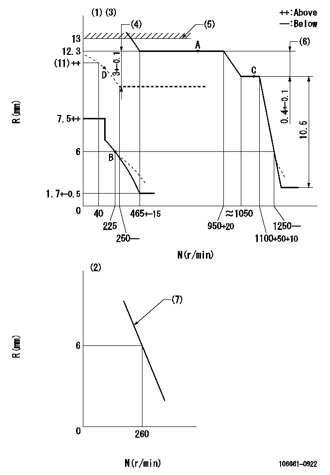
N:Pump speed
R:Rack position (mm)
(1)Adjust with speed control lever at full position (minimum-maximum speed specification)
(2)Adjust with the load control lever in the full position (variable speed specification).
(3)Beginning of damper spring operation: DL
(4)Boost compensator stroke
(5)Rack limit using stop lever
(6)Rack difference between N = N1 and N = N2
(7)Main spring setting
----------
DL=4.8-0.2mm N1=1100r/min N2=650r/min
----------
----------
DL=4.8-0.2mm N1=1100r/min N2=650r/min
----------
Speed control lever angle
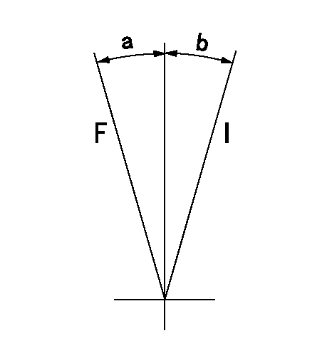
F:Full speed
I:Idle
----------
----------
a=10deg+-5deg b=(13deg)+-5deg
----------
----------
a=10deg+-5deg b=(13deg)+-5deg
0000000901
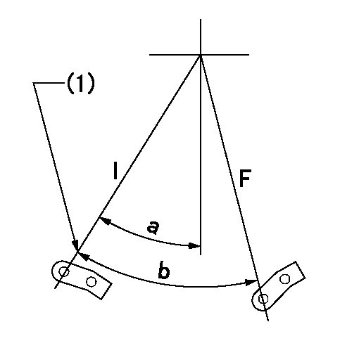
F:Full load
I:Idle
(1)Stopper bolt setting
----------
----------
a=32.5deg+-5deg b=38deg+-3deg
----------
----------
a=32.5deg+-5deg b=38deg+-3deg
Stop lever angle
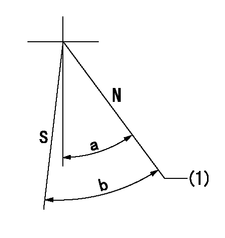
N:Pump normal
S:Stop the pump.
(1)Rack position = aa
----------
aa=13mm
----------
a=32deg+-5deg b=34deg+-5deg
----------
aa=13mm
----------
a=32deg+-5deg b=34deg+-5deg
Timing setting

(1)Pump vertical direction
(2)Coupling's key groove position at No 1 cylinder's beginning of injection
(3)-
(4)-
----------
----------
a=(30deg)
----------
----------
a=(30deg)
Information:
Introduction
The following procedures contain crucial information on correctly installing the new 162-2501 Hose As and the 258-8917 Protection Sleeve .Note: The 162-2501 Hose As replaces 107-7942 Tube As .Installation Procedure of the Hose Assembly
Illustration 1 g01230674
Remove old 162-2501 Hose As (1). Keep all of the manifold and pump fittings attached.Note: Step 2 is only for 3408E engines.
Remove the 7W-6492 Pipe Plug (2) from the aftercooler housing (3). Install the 8T-6762 Pipe Plug into the aftercooler housing.
Illustration 2 g01230678
Note: Always tighten the fittings with your hand before you use a wrench. Support the hose and the elbow while you tighten in order to avoid the following damage: twisting, kinking and side loading.
Loosen elbow (4) and jam nut (5) .
Hand tighten the nut on the hose (5) to the elbow (4) .
Install the other end of the hose (6) to the pump fitting. Tighten the nut to 125 15 N m (90 11 lb ft).
Hold the elbow (4) in position and torque the jam nut to 145 15 N m (105 11 lb ft).
Support the elbow (4). Tighten the nut (5) on the hose to 125 15 N m (90 11 lb ft).
Illustration 3 g01230687
Illustration 3 shows the routing of the 162-2501 Hose As (8). The hose is routed from the rail, around the rear of the fuel transfer pump (9), and into the 90 degree fitting (7) that is installed into the pump.
Illustration 4 g01230689
Some 3408 engines use an aftercooler that is mounted high. The mounting bracket (10) is located close to the 162-2501 Hose As (8). If there is not enough clearance to install the protective sleeve, the hose will need to be loosened and the hose will need to be repositioned. Refer to 5 for repositioning of the hose.
Illustration 5 g01230690
The hose must be realigned if any of the following conditions exist:
Not enough clearance against the fuel transfer pump
Not enough clearance against the support bracket
Loosen the end of the hose (12) .
Loosen the elbow and the jam nut (11). Note: Do not remove the hose.
Reposition the hose in order to acquire the desired clearance.
Hold the end of the hose (12). Tighten the jam nut (11) .Tighten the jam nut to the following torque. ... 143 15 N m (105 11 lb ft)Note: Locking pliers can be used on the crimped portion of the hose. Do not use the locking pliers on the braided portion of the hose. This will damage the hose which will cause a failure.
Tighten the end of the hose (12) .Tighten the end of the hose to the following torque. ... 125 15 N m (92 11 lb ft)Note: If adjustment of the hose is required, make sure that the hose is not bent. Also, ensure that the hose is not twisted. If these conditions exist the PTFE liner can be damaged.Installation of the Protective Sleeve Over the New Hose Assembly
Illustration 6 g01106118
Top viewInstallation of a protective sleeve for the hoses of the