Information injection-pump assembly
ZEXEL
106661-0710
1066610710
NISSAN-DIESEL
1670096111
1670096111
Rating:
Cross reference number
ZEXEL
106661-0710
1066610710
NISSAN-DIESEL
1670096111
1670096111
Zexel num
Bosch num
Firm num
Name
106661-0710
1670096111 NISSAN-DIESEL
INJECTION-PUMP ASSEMBLY
PD6 *
PD6 *
Calibration Data:
Adjustment conditions
Test oil
1404 Test oil ISO4113 or {SAEJ967d}
1404 Test oil ISO4113 or {SAEJ967d}
Test oil temperature
degC
40
40
45
Nozzle and nozzle holder
105780-8140
Bosch type code
EF8511/9A
Nozzle
105780-0000
Bosch type code
DN12SD12T
Nozzle holder
105780-2080
Bosch type code
EF8511/9
Opening pressure
MPa
17.2
Opening pressure
kgf/cm2
175
Injection pipe
Outer diameter - inner diameter - length (mm) mm 8-3-600
Outer diameter - inner diameter - length (mm) mm 8-3-600
Overflow valve
132424-0620
Overflow valve opening pressure
kPa
157
123
191
Overflow valve opening pressure
kgf/cm2
1.6
1.25
1.95
Tester oil delivery pressure
kPa
157
157
157
Tester oil delivery pressure
kgf/cm2
1.6
1.6
1.6
Direction of rotation (viewed from drive side)
Right R
Right R
Injection timing adjustment
Direction of rotation (viewed from drive side)
Right R
Right R
Injection order
1-4-2-6-
3-5
Pre-stroke
mm
3.65
3.6
3.7
Beginning of injection position
Drive side NO.1
Drive side NO.1
Difference between angles 1
Cal 1-4 deg. 60 59.5 60.5
Cal 1-4 deg. 60 59.5 60.5
Difference between angles 2
Cyl.1-2 deg. 120 119.5 120.5
Cyl.1-2 deg. 120 119.5 120.5
Difference between angles 3
Cal 1-6 deg. 180 179.5 180.5
Cal 1-6 deg. 180 179.5 180.5
Difference between angles 4
Cal 1-3 deg. 240 239.5 240.5
Cal 1-3 deg. 240 239.5 240.5
Difference between angles 5
Cal 1-5 deg. 300 299.5 300.5
Cal 1-5 deg. 300 299.5 300.5
Injection quantity adjustment
Adjusting point
A
Rack position
11.7
Pump speed
r/min
750
750
750
Average injection quantity
mm3/st.
139.4
137.4
141.4
Max. variation between cylinders
%
0
-4
4
Basic
*
Fixing the rack
*
Injection quantity adjustment_02
Adjusting point
B
Rack position
10.9
Pump speed
r/min
400
400
400
Average injection quantity
mm3/st.
114.6
112.6
116.6
Max. variation between cylinders
%
0
-4
4
Fixing the lever
*
Injection quantity adjustment_03
Adjusting point
C
Rack position
11.7
Pump speed
r/min
1000
1000
1000
Average injection quantity
mm3/st.
139.7
137.7
141.7
Max. variation between cylinders
%
0
-4
4
Fixing the rack
*
Injection quantity adjustment_04
Adjusting point
D
Rack position
11.7
Pump speed
r/min
1150
1150
1150
Average injection quantity
mm3/st.
138.8
136.8
140.8
Max. variation between cylinders
%
0
-4
4
Fixing the rack
*
Injection quantity adjustment_05
Adjusting point
E
Rack position
7.2+-0.5
Pump speed
r/min
200
200
200
Average injection quantity
mm3/st.
10.1
9.1
11.1
Max. variation between cylinders
%
0
-10
10
Fixing the rack
*
Injection quantity adjustment_06
Adjusting point
-
Rack position
-
Pump speed
r/min
750
750
750
Average injection quantity
mm3/st.
139.4
138.4
140.4
Fixing the lever
*
Boost pressure
kPa
53.3
53.3
53.3
Boost pressure
mmHg
400
400
400
Remarks
Set full load lever
Set full load lever
Boost compensator adjustment
Pump speed
r/min
400
400
400
Rack position
10.9
Boost pressure
kPa
27.3
27.3
27.3
Boost pressure
mmHg
205
205
205
Boost compensator adjustment_02
Pump speed
r/min
400
400
400
Rack position
11.7
Boost pressure
kPa
42.7
41.4
44
Boost pressure
mmHg
320
310
330
Timer adjustment
Pump speed
r/min
500+-50
Advance angle
deg.
0
0
0
Remarks
Start
Start
Timer adjustment_02
Pump speed
r/min
700
Advance angle
deg.
0.2
0.1
0.6
Timer adjustment_03
Pump speed
r/min
900
Advance angle
deg.
0.7
0.3
1
Timer adjustment_04
Pump speed
r/min
1150+50
Advance angle
deg.
2.2
2
2.8
Remarks
Finish
Finish
Test data Ex:
Governor adjustment
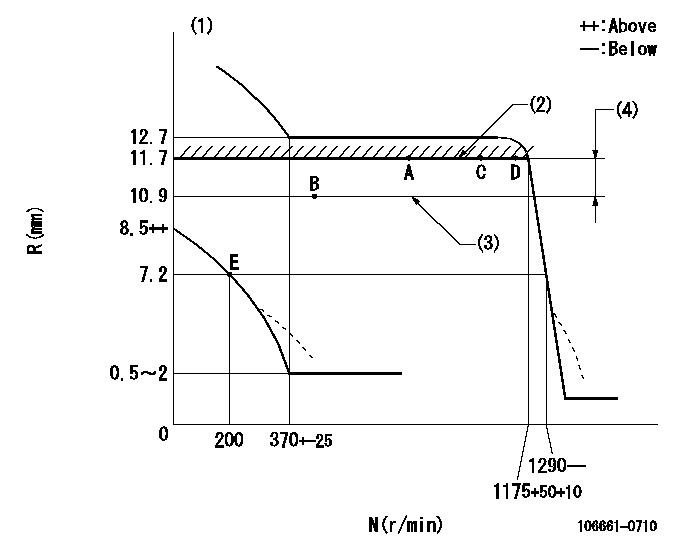
N:Pump speed
R:Rack position (mm)
(1)Beginning of damper spring operation: DL
(2)Boost pressure: not exceeding BP1
(3)Boost pressure: not exceeding BP2
(4)Boost compensator stroke
----------
DL=5.2+0.5mm BP1=42.7+-1.3kPa(320+-10mmHg) BP2=(27.3)kPa((205)mmHg)
----------
----------
DL=5.2+0.5mm BP1=42.7+-1.3kPa(320+-10mmHg) BP2=(27.3)kPa((205)mmHg)
----------
0000000901

F:Full load
I:Idle
(1)Stopper bolt setting
----------
----------
a=13.5deg+-5deg b=23.5deg+-3deg
----------
----------
a=13.5deg+-5deg b=23.5deg+-3deg
Information:
Contact with high pressure fuel may cause fluid penetration and burn hazards. High pressure fuel spray may cause a fire hazard. Failure to follow these inspection, maintenance and service instructions may cause personal injury or death.
Ensure that all adjustments and repairs that are carried out to the fuel system are performed by authorised personnel that have the correct training.Before begining ANY work on the fuel system, refer to Operation and Maintenance Manual, "General Hazard Information and High Pressure Fuel Lines" for safety information.Refer to Systems Operation, Testing and Adjusting Manual, "Cleanliness of Fuel System Components" for detailed information on the standards of cleanliness that must be observed
Have questions with 106661-0710?
Group cross 106661-0710 ZEXEL
Nissan-Diesel
Nissan-Diesel
106661-0710
1670096111
INJECTION-PUMP ASSEMBLY
PD6
PD6