Information injection-pump assembly
ZEXEL
106661-0650
1066610650
Rating:
Cross reference number
ZEXEL
106661-0650
1066610650
Zexel num
Bosch num
Firm num
Name
Calibration Data:
Adjustment conditions
Test oil
1404 Test oil ISO4113 or {SAEJ967d}
1404 Test oil ISO4113 or {SAEJ967d}
Test oil temperature
degC
40
40
45
Nozzle and nozzle holder
105780-8140
Bosch type code
EF8511/9A
Nozzle
105780-0000
Bosch type code
DN12SD12T
Nozzle holder
105780-2080
Bosch type code
EF8511/9
Opening pressure
MPa
17.2
Opening pressure
kgf/cm2
175
Injection pipe
Outer diameter - inner diameter - length (mm) mm 8-3-600
Outer diameter - inner diameter - length (mm) mm 8-3-600
Overflow valve opening pressure
kPa
157
123
191
Overflow valve opening pressure
kgf/cm2
1.6
1.25
1.95
Tester oil delivery pressure
kPa
157
157
157
Tester oil delivery pressure
kgf/cm2
1.6
1.6
1.6
Direction of rotation (viewed from drive side)
Right R
Right R
Injection timing adjustment
Direction of rotation (viewed from drive side)
Right R
Right R
Injection order
1-4-2-6-
3-5
Pre-stroke
mm
3.65
3.6
3.7
Beginning of injection position
Drive side NO.1
Drive side NO.1
Difference between angles 1
Cal 1-4 deg. 60 59.5 60.5
Cal 1-4 deg. 60 59.5 60.5
Difference between angles 2
Cyl.1-2 deg. 120 119.5 120.5
Cyl.1-2 deg. 120 119.5 120.5
Difference between angles 3
Cal 1-6 deg. 180 179.5 180.5
Cal 1-6 deg. 180 179.5 180.5
Difference between angles 4
Cal 1-3 deg. 240 239.5 240.5
Cal 1-3 deg. 240 239.5 240.5
Difference between angles 5
Cal 1-5 deg. 300 299.5 300.5
Cal 1-5 deg. 300 299.5 300.5
Injection quantity adjustment
Adjusting point
A
Rack position
11.3
Pump speed
r/min
740
740
740
Average injection quantity
mm3/st.
122
120
124
Max. variation between cylinders
%
0
-4
4
Basic
*
Fixing the lever
*
Boost pressure
kPa
26.7
26.7
Boost pressure
mmHg
200
200
Injection quantity adjustment_02
Adjusting point
B
Rack position
10.7
Pump speed
r/min
400
400
400
Average injection quantity
mm3/st.
98.6
96.6
100.6
Max. variation between cylinders
%
0
-4
4
Fixing the lever
*
Boost pressure
kPa
0
0
0
Boost pressure
mmHg
0
0
0
Injection quantity adjustment_03
Adjusting point
C
Rack position
7.2+-0.5
Pump speed
r/min
225
225
225
Average injection quantity
mm3/st.
13.3
11.6
15
Max. variation between cylinders
%
0
-10
10
Fixing the rack
*
Boost pressure
kPa
0
0
0
Boost pressure
mmHg
0
0
0
Boost compensator adjustment
Pump speed
r/min
500
500
500
Rack position
10.7
Boost pressure
kPa
6.7
4
9.4
Boost pressure
mmHg
50
30
70
Boost compensator adjustment_02
Pump speed
r/min
500
500
500
Rack position
11.3
Boost pressure
kPa
15.3
15.3
15.3
Boost pressure
mmHg
115
115
115
Timer adjustment
Pump speed
r/min
500+-50
Advance angle
deg.
0
0
0
Remarks
Start
Start
Timer adjustment_02
Pump speed
r/min
700
Advance angle
deg.
0.75
0.4
1.1
Timer adjustment_03
Pump speed
r/min
900
Advance angle
deg.
1.25
0.9
1.6
Timer adjustment_04
Pump speed
r/min
1100+50
Advance angle
deg.
2.5
1.9
2.7
Remarks
Finish
Finish
Test data Ex:
Governor adjustment
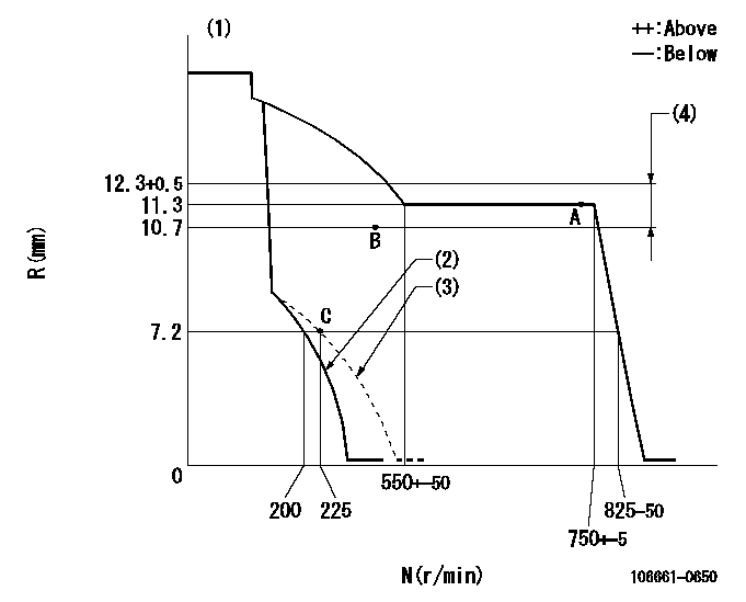
N:Pump speed
R:Rack position (mm)
(1)Target notch: K
(2)Stop lever setting
(3)Set idle sub-spring
(4)Boost compensator stroke
----------
K=15
----------
----------
K=15
----------
Speed control lever angle

F:Full speed
I:Idle
(1)Stopper bolt setting
----------
----------
a=5deg+-5deg b=23deg+-3deg
----------
----------
a=5deg+-5deg b=23deg+-3deg
Stop lever angle
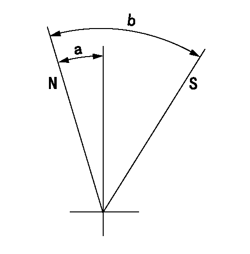
N:Pump normal
S:Stop the pump.
----------
----------
a=10.5deg+-5deg b=53deg+-5deg
----------
----------
a=10.5deg+-5deg b=53deg+-5deg
Information:
Parts Location
Illustration 2 g01601133
(1) 308-4927 Diesel Particulate Filter and Mounting Gp (2) 235-3963 Clamp As (3) 308-4930 Bracket As (4) 8T-4183 Bolt (5) 5P-8245 Hard Washer (6) 5P-1076 Hard Washer Installation Procedure
Diesel Particulate Filter Installation
Illustration 3 g01624741
Left side view (typical example) (12) Muffler assembly (existing) (13) Bracket assembly (existing) (14) Bolt (existing) (15) Washer (existing)
Illustration 4 g01624810
Rear view (typical example) (16) Bolt (existing) (17) Hard washer (existing) (18) Muffler clamp (existing) (19) Tube assembly (existing)
Remove muffler assembly (12). Retain muffler clamp (18). The muffler clamp will be reused in Step 8. Refer to Illustrations 3 and 4.Note: A new 289-2492 Muffler Clamp (11) will be needed if the original muffler clamp cannot be reused.
Remove bracket assembly (13). Retain five bolts (14), five washers (15), two bolts (16), and two hard washers (17) that were used to secure bracket assembly (13). These parts will be reused in Step 3.
Illustration 5 g01601033
(3) 308-4930 Bracket As (4) 8T-4183 Bolt (6) 5P-1076 Hard Washer
Reuse five bolts (14), and five washers (15) to secure the new 308-4930 Bracket As (3) to the flywheel housing. Refer to Illustration 5.
Reuse two bolts (16), and two hard washers (17) to secure bracket assembly (3) to the engine lifting plate. Refer to Illustration 5.
Install two new 8T-4183 Bolts (4), and two new 5P-1076 Hard Washers (6) to the other side of bracket assembly (3) so that the bracket assembly is bolted to the engine and to the enclosure on both sides. Refer to Illustration 5.
Illustration 6 g01601025
(2) 235-3963 Clamp As (Bottom half) (4) 8T-4183 Bolt (5) 5P-8245 Hard Washer
Remove the two bolts, two hard washers, two lockwashers, and two nuts from the new 235-3963 Clamp As (2). Repeat for the other new clamp assembly (2). Retain these parts along with the upper half of the clamp assembly. These parts will be reinstalled in Step 9.
Install the bottom half of 235-3963 Clamp As (2) by using two new 8T-4183 Bolts (4) and two new 5P-8245 Hard Washers (5). Loosely secure these bolts so that the clamp assembly is adjustable. Repeat for the other clamp assembly. Refer to Illustration 6.
Illustration 7 g01601013
(1) 308-4927 Diesel Particulate Filter and Mounting Gp (2) 235-3963 Clamp As (Top half) (2a) Bolt (2b) Hard washer (2c) Lockwasher (2d) Nut (20) Inlet module tube
Install the new 308-4927 Diesel Particulate Filter and Mounting Gp (1) on top of clamp assemblies (2). The weight of the diesel particulate filter group is approximately 34 kg (75 lb). Make sure that inlet module tube (20) fits into tube assembly (19). Secure the inlet module tube to the tube assembly by using original muffler clamp (18). If the original muffler clamp (18) cannot be reused, use a new 289-2492 Muffler Clamp (11) to secure the connection. This clamp is not included in the kit. Refer to Illustration 7.
Once you have the