Information injection-pump assembly
ZEXEL
106661-0270
1066610270

Rating:
Cross reference number
ZEXEL
106661-0270
1066610270
Zexel num
Bosch num
Firm num
Name
Calibration Data:
Adjustment conditions
Test oil
1404 Test oil ISO4113 or {SAEJ967d}
1404 Test oil ISO4113 or {SAEJ967d}
Test oil temperature
degC
40
40
45
Nozzle
105015-3100
Bosch type code
DLLA166S414NP46
Nozzle holder
105031-4140
Opening pressure
MPa
22.6
Opening pressure
kgf/cm2
230
Injection pipe
Outer diameter - inner diameter - length (mm) mm 6-2-500
Outer diameter - inner diameter - length (mm) mm 6-2-500
Overflow valve
132424-0620
Overflow valve opening pressure
kPa
157
123
191
Overflow valve opening pressure
kgf/cm2
1.6
1.25
1.95
Tester oil delivery pressure
kPa
157
157
157
Tester oil delivery pressure
kgf/cm2
1.6
1.6
1.6
Direction of rotation (viewed from drive side)
Right R
Right R
Injection timing adjustment
Direction of rotation (viewed from drive side)
Right R
Right R
Injection order
1-4-2-6-
3-5
Pre-stroke
mm
3.65
3.6
3.7
Beginning of injection position
Drive side NO.1
Drive side NO.1
Difference between angles 1
Cal 1-4 deg. 60 59.5 60.5
Cal 1-4 deg. 60 59.5 60.5
Difference between angles 2
Cyl.1-2 deg. 120 119.5 120.5
Cyl.1-2 deg. 120 119.5 120.5
Difference between angles 3
Cal 1-6 deg. 180 179.5 180.5
Cal 1-6 deg. 180 179.5 180.5
Difference between angles 4
Cal 1-3 deg. 240 239.5 240.5
Cal 1-3 deg. 240 239.5 240.5
Difference between angles 5
Cal 1-5 deg. 300 299.5 300.5
Cal 1-5 deg. 300 299.5 300.5
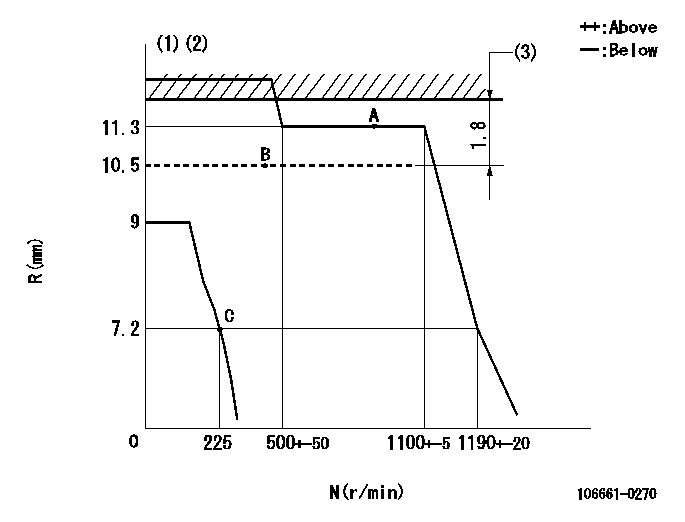
Injection quantity adjustment
Adjusting point
A
Rack position
11.3
Pump speed
r/min
750
750
750
Average injection quantity
mm3/st.
127
125
129
Max. variation between cylinders
%
0
-4
4
Basic
*
Fixing the lever
*
Boost pressure
kPa
26.7
26.7
26.7
Boost pressure
mmHg
200
200
200
Injection quantity adjustment_02
Adjusting point
B
Rack position
10.5
Pump speed
r/min
400
400
400
Average injection quantity
mm3/st.
101
99
103
Max. variation between cylinders
%
0
-4
4
Fixing the lever
*
Boost pressure
kPa
0
0
0
Boost pressure
mmHg
0
0
0
Injection quantity adjustment_03
Adjusting point
C
Rack position
7.2+-0.5
Pump speed
r/min
225
225
225
Average injection quantity
mm3/st.
17
15.3
18.7
Max. variation between cylinders
%
0
-10
10
Fixing the rack
*
Boost compensator adjustment
Pump speed
r/min
500
500
500
Rack position
10.5
Boost pressure
kPa
7.3
4.6
10
Boost pressure
mmHg
55
35
75
Boost compensator adjustment_02
Pump speed
r/min
500
500
500
Rack position
11.3
Boost pressure
kPa
24.7
24.7
24.7
Boost pressure
mmHg
185
185
185
Boost compensator adjustment_03
Pump speed
r/min
500
500
500
Rack position
12.3
Remarks
Measure actual boost pressure.
Measure actual boost pressure.
Timer adjustment
Pump speed
r/min
500+-50
Advance angle
deg.
0
0
0
Remarks
Start
Start
Timer adjustment_02
Pump speed
r/min
700
Advance angle
deg.
0.75
0.4
1.1
Timer adjustment_03
Pump speed
r/min
900
Advance angle
deg.
1.25
0.9
1.6
Timer adjustment_04
Pump speed
r/min
1100+50
Advance angle
deg.
2.5
1.9
2.7
Remarks
Finish
Finish
Test data Ex:
Governor adjustment
N:Pump speed
R:Rack position (mm)
(1)Target notch: K
(2)Solenoid operation confirmation: Set the speed control lever in the full speed position. At pump speed N1 when the solenoid is operated, confirm that the idle rack position is R1 or less.
(3)Boost compensator stroke
----------
K=15 N1=100r/min R1=-1mm
----------
----------
K=15 N1=100r/min R1=-1mm
----------
Speed control lever angle
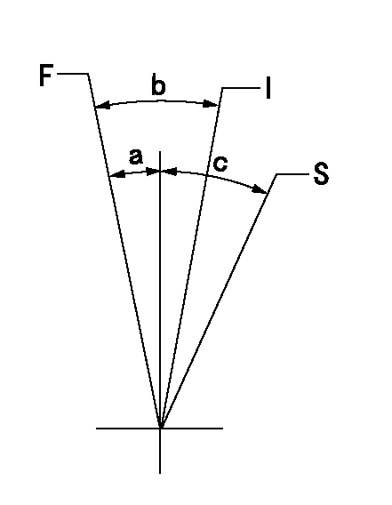
F:Full speed
I:Idle
S:Stop
----------
----------
a=17.5deg+-5deg b=27deg+-5deg c=32deg+-3deg
----------
----------
a=17.5deg+-5deg b=27deg+-5deg c=32deg+-3deg
Stop lever angle

N:Pump normal
S:Stop the pump.
----------
----------
a=(29deg) b=(47deg)
----------
----------
a=(29deg) b=(47deg)
Information:
Illustration 16 g00628694
(9) Fuel injector clamp. (10) Bolt. (11) O-ring seal.
Place the clamp (9) in the proper position. Temporarily place the jumper tube in position in order to ensure alignment of the bolt holes. Adjust the orientation of the injector until the alignment is satisfactory. Torque the bolt (10) to the following torque. Remove the jumper tube.Torque for bolt ... 47 9 N m (35 7 lb ft)
Illustration 17 g00628691
(12) O-ring seals in the injector jumper tube. (13) O-ring seals in the base of the rocker arm.
Replace the used O-ring seal (11), and the O-ring seals (12) and (13) in the jumper tube and in the rocker arm.
Illustration 18 g00628693
(14) Jumper tube. (15) Bolts. (16) Adapter. (17) Socket head screws.
Place the jumper tube (14) and the adapter (16) into position.
If the adapter was previously installed on the injector, loosen the socket head screws. Failure to loosen the socket head screws before continuing with Step 8 can result in injector failure.
Install the socket head screws (17) and the four bolts (15) finger tight.Note: The mating surfaces should be brought into complete contact and into alignment before the final torque procedure is started.
Failure to follow any of the procedures in this instruction may result in injector damage or malfunction, and possible major engine damage.
Torque Procedure
Illustration 19 g00338156
(1) Socket head screws.
Illustration 20 g00338157
(2) Two horizontal bolts. (3) Two vertical bolts.
Tighten the socket head screws (1), the two horizontal bolts (2), and the two vertical bolts (3) finger tight.
Tighten the socket head screws (1) to an initial torque of 1 .2 N m (9 2 lb in).
Tighten the horizontal bolts (2) to an initial torque of 5 3 N m (44 27 lb in).
Tighten the vertical bolts (3) to an initial torque of 5 3 N m (44 27 lb in).
Tighten the socket head screws (1) to a final torque of 12 3 N m (9 2 lb ft).
Tighten the horizontal bolts (2) to a final torque of 47 9 N m (35 7 lb ft).
Tighten the vertical bolts (3) to a final torque of 47 9 N m (35 7 lb ft).
Repeat Step 1 through Step 7 for the remainder of the injectors.
Check the fuel system for leaks by cranking the engine with the disabled injection. Then check the hydraulic pressure. Compare the pressure to the desired pressure.Cranking Without Injecting
Cranking the engine with the disabled injection may be performed by one of the following methods:
Disconnect the injector harness of the cylinders which have been reinstalled. Allow the engine to idle. Visually inspect the injector's components for high pressure oil leaks.
Activate the system "Crank Without Inject" if the option is available. On Track-Type Tractors, a "Crank Without Inject" plug can be assembled in the engine harness. On Off-Highway Trucks, the "Ground Level Shutdown" can be activated if the option is available.
When you are using the CAT ET or the ECAP, the injection may be disabled by interactive diagnostics. The engine can be left