Information injection-pump assembly
ZEXEL
106652-4060
1066524060
NIIGATA-URAWA
40947040B
40947040b
Rating:
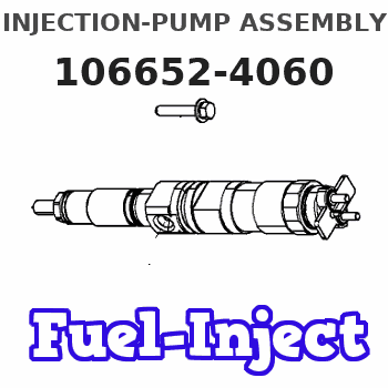
Service parts 106652-4060 INJECTION-PUMP ASSEMBLY:
1.
_
5.
AUTOM. ADVANCE MECHANIS
6.
COUPLING PLATE
7.
COUPLING PLATE
8.
_
9.
_
11.
Nozzle and Holder
510 3225 1A
12.
Open Pre:MPa(Kqf/cm2)
14.7{150}
15.
NOZZLE SET
Include in #1:
106652-4060
as INJECTION-PUMP ASSEMBLY
Cross reference number
ZEXEL
106652-4060
1066524060
NIIGATA-URAWA
40947040B
40947040b
Zexel num
Bosch num
Firm num
Name
Calibration Data:
Adjustment conditions
Test oil
1404 Test oil ISO4113 or {SAEJ967d}
1404 Test oil ISO4113 or {SAEJ967d}
Test oil temperature
degC
40
40
45
Nozzle and nozzle holder
105780-8130
Bosch type code
EFEP215A
Nozzle
105780-0050
Bosch type code
DN6TD119NP1T
Nozzle holder
105780-2090
Bosch type code
EFEP215
Opening pressure
MPa
17.2
Opening pressure
kgf/cm2
175
Injection pipe
Outer diameter - inner diameter - length (mm) mm 8-3-600
Outer diameter - inner diameter - length (mm) mm 8-3-600
Tester oil delivery pressure
kPa
157
157
157
Tester oil delivery pressure
kgf/cm2
1.6
1.6
1.6
Direction of rotation (viewed from drive side)
Right R
Right R
Injection timing adjustment
Direction of rotation (viewed from drive side)
Right R
Right R
Injection order
1-3-5-6-
4-2
Pre-stroke
mm
2.7
2.65
2.75
Beginning of injection position
Drive side NO.1
Drive side NO.1
Difference between angles 1
Cal 1-3 deg. 60 59.5 60.5
Cal 1-3 deg. 60 59.5 60.5
Difference between angles 2
Cal 1-5 deg. 120 119.5 120.5
Cal 1-5 deg. 120 119.5 120.5
Difference between angles 3
Cal 1-6 deg. 180 179.5 180.5
Cal 1-6 deg. 180 179.5 180.5
Difference between angles 4
Cal 1-4 deg. 240 239.5 240.5
Cal 1-4 deg. 240 239.5 240.5
Difference between angles 5
Cyl.1-2 deg. 300 299.5 300.5
Cyl.1-2 deg. 300 299.5 300.5
Injection quantity adjustment
Adjusting point
A
Rack position
14.8
Pump speed
r/min
600
600
600
Average injection quantity
mm3/st.
304
295
313
Max. variation between cylinders
%
0
-3
3
Basic
*
Fixing the rack
*
Injection quantity adjustment_02
Adjusting point
B
Rack position
6.1+-0.5
Pump speed
r/min
500
500
500
Average injection quantity
mm3/st.
29.5
25.5
33.5
Max. variation between cylinders
%
0
-10
10
Fixing the rack
*
Test data Ex:
Governor adjustment
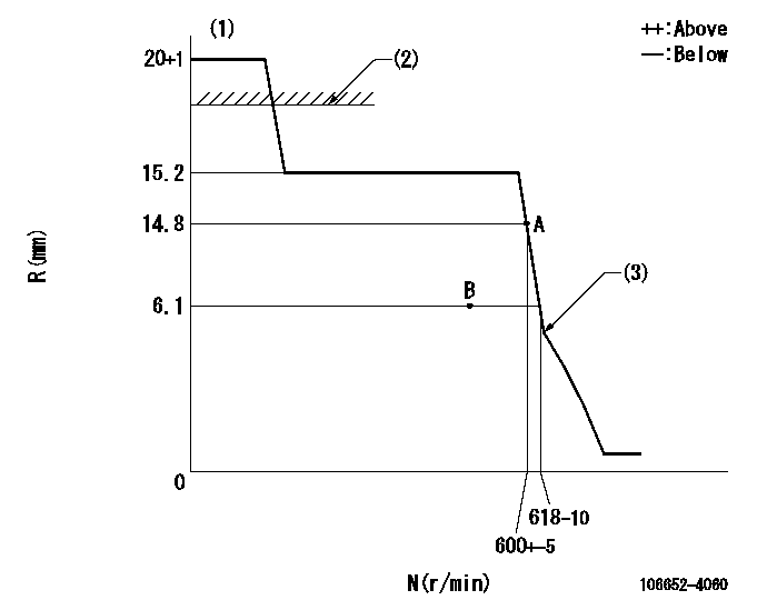
N:Pump speed
R:Rack position (mm)
(1)Target notch: K
(2)RACK LIMIT: RAL (N = N1)
(3)Idle sub spring setting: L1.
----------
K=14 RAL=16+0.2mm N1=0r/min L1=5.1-0.5mm
----------
----------
K=14 RAL=16+0.2mm N1=0r/min L1=5.1-0.5mm
----------
Speed control lever angle
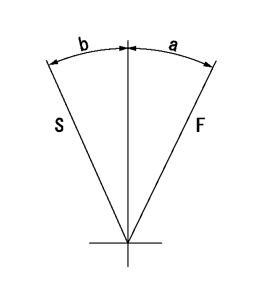
F:Full speed
S:Stop
----------
----------
a=13deg+-5deg b=32deg+-3deg
----------
----------
a=13deg+-5deg b=32deg+-3deg
Stop lever angle
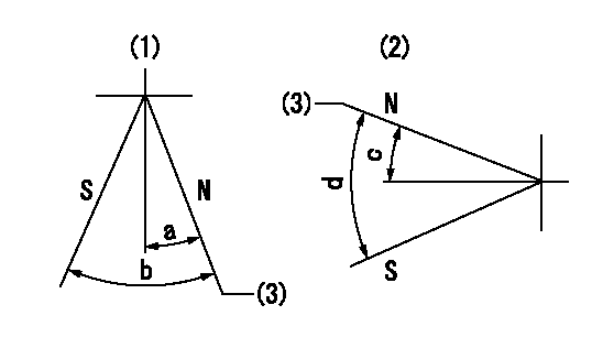
N:Pump normal
S:Stop the pump.
(1)Right front
(2)Right rear
(3)Normal
----------
----------
a=24.5deg+-5deg b=47deg+-5deg c=27deg+-5deg d=53deg+-5deg
----------
----------
a=24.5deg+-5deg b=47deg+-5deg c=27deg+-5deg d=53deg+-5deg
Timing setting

(1)Pump vertical direction
(2)Position of pump side coupling's reamer bolt hole at No 1 cylinder's beginning of injection
(3)-
(4)-
----------
----------
a=(50deg)
----------
----------
a=(50deg)
Information:
26Feb2020
U-93
A-70
D-86
O-82
Parts stock action only
PRODUCT IMPROVEMENT PROGRAM FOR INSPECTING AND POSSIBLY REMOVING CERTAIN 471-6029 DEF INJECTOR AND MOUNTING GROUPS FROM DEALER PARTS STOCK
108I 7750 PI70799
Caterpillar’s obligations under this Service Letter are subject to, and shall not apply in contravention of, the laws, rules, regulations, directives, ordinances, orders, or statutes of the United States, or of any other applicable jurisdiction, without recourse or liability with respect to Caterpillar.
When submitting claim for Parts Stock Action, Use the appropriate 99Z as the s/n, the appropriate Service Letter Program Number as the Part number in the Part Causing Failure field, "7751" as the Group Number, "56" as the Description Code.
The information supplied in this service letter may not be valid after the termination date of this program.Do not perform the work outlined in this Service Letter after the termination date without first contacting your Caterpillar product analyst.
TERMINATION DATE
31May2020
PROBLEM
A defined batch of existing 471-6029 DEF Injector and Mounting Groups can fail under certain conditions.
ACTION REQUIRED
Inspect all 471-6029 DEF Injector and Mounting Groups in dealer parts stock.
Open the packaging and visually inspect the DEF injector.
If the DEF injector's upper body molding mark is an A or B, then the DEF injector is acceptable to use. Repackage the DEF injector and mark the packaging as inspected per this program and place the part back into dealer parts stock.
If the DEF injector's upper body molding mark is a 1 or 2, then remove the part from dealer parts stock. Refer to the Parts Disposition.
Image 1 shows the molding marks and location.
Image1
SERVICE CLAIM ALLOWANCES
Submit one claim for all parts removed from dealer parts stock.
PARTS DISPOSITION
NACD:
Hold all 471-6029 DEF Injector and Mounting Groups removed from dealer parts stock for a Parts Return Request (PRR). A Parts Return Request (PRR) will be issued to you through the Send-It-Back process after the claim is submitted. Make sure to list the service letter program number on the packing slip and include the closed work order paperwork. Handle all other parts in accordance with your Warranty Bulletin on warranty parts handling.
If a Parts Return Request (PRR) is not issued to you after 30 days through the Send-It-Back process, handle the parts in accordance with your warranty bulletin on warranty parts handling.
EAME, LACD, and APD:
Hold all 471-6029 DEF Injector and Mounting Groups removed from dealer parts stock for 30 days for a possible Parts Return Request (PRR). Make sure to list the service letter program number on the packing slip and include the closed work order paperwork. Handle all other parts in accordance with your Warranty Bulletin on warranty parts handling.
If a Parts Return Request (PRR) is not issued to you after 30 days through the Send-It-Back process, handle the parts in accordance with your warranty bulletin on warranty parts handling.