Information injection-pump assembly
ZEXEL
106651-2140
1066512140

Rating:
Cross reference number
ZEXEL
106651-2140
1066512140
Zexel num
Bosch num
Firm num
Name
Calibration Data:
Adjustment conditions
Test oil
1404 Test oil ISO4113 or {SAEJ967d}
1404 Test oil ISO4113 or {SAEJ967d}
Test oil temperature
degC
40
40
45
Nozzle and nozzle holder
105780-8140
Bosch type code
EF8511/9A
Nozzle
105780-0000
Bosch type code
DN12SD12T
Nozzle holder
105780-2080
Bosch type code
EF8511/9
Opening pressure
MPa
17.2
Opening pressure
kgf/cm2
175
Injection pipe
Outer diameter - inner diameter - length (mm) mm 8-3-600
Outer diameter - inner diameter - length (mm) mm 8-3-600
Overflow valve opening pressure
kPa
157
123
191
Overflow valve opening pressure
kgf/cm2
1.6
1.25
1.95
Tester oil delivery pressure
kPa
157
157
157
Tester oil delivery pressure
kgf/cm2
1.6
1.6
1.6
Direction of rotation (viewed from drive side)
Right R
Right R
Injection timing adjustment
Direction of rotation (viewed from drive side)
Right R
Right R
Injection order
1-5-3-6-
2-4
Pre-stroke
mm
5.1
5.05
5.15
Beginning of injection position
Governor side NO.1
Governor side NO.1
Difference between angles 1
Cal 1-5 deg. 60 59.5 60.5
Cal 1-5 deg. 60 59.5 60.5
Difference between angles 2
Cal 1-3 deg. 120 119.5 120.5
Cal 1-3 deg. 120 119.5 120.5
Difference between angles 3
Cal 1-6 deg. 180 179.5 180.5
Cal 1-6 deg. 180 179.5 180.5
Difference between angles 4
Cyl.1-2 deg. 240 239.5 240.5
Cyl.1-2 deg. 240 239.5 240.5
Difference between angles 5
Cal 1-4 deg. 300 299.5 300.5
Cal 1-4 deg. 300 299.5 300.5
Injection quantity adjustment
Adjusting point
-
Rack position
12.1
Pump speed
r/min
700
700
700
Each cylinder's injection qty
mm3/st.
140
136.5
143.5
Basic
*
Fixing the rack
*
Standard for adjustment of the maximum variation between cylinders
*
Injection quantity adjustment_02
Adjusting point
C
Rack position
6.3+-0.5
Pump speed
r/min
225
225
225
Each cylinder's injection qty
mm3/st.
18.6
15.9
21.3
Fixing the rack
*
Standard for adjustment of the maximum variation between cylinders
*
Injection quantity adjustment_03
Adjusting point
A
Rack position
R1(12.1)
Pump speed
r/min
700
700
700
Average injection quantity
mm3/st.
140
139
141
Basic
*
Fixing the lever
*
Boost pressure
kPa
63.3
63.3
Boost pressure
mmHg
475
475
Injection quantity adjustment_04
Adjusting point
B
Rack position
R1(12.1)
Pump speed
r/min
1100
1100
1100
Average injection quantity
mm3/st.
139
135
143
Difference in delivery
mm3/st.
8
8
8
Fixing the lever
*
Boost pressure
kPa
63.3
63.3
Boost pressure
mmHg
475
475
Injection quantity adjustment_05
Adjusting point
D
Rack position
11.5
Pump speed
r/min
500
500
500
Average injection quantity
mm3/st.
121
117.4
124.6
Fixing the lever
*
Boost pressure
kPa
33.3
33.3
33.3
Boost pressure
mmHg
250
250
250
Injection quantity adjustment_06
Adjusting point
E
Rack position
-
Pump speed
r/min
100
100
100
Average injection quantity
mm3/st.
110
90
130
Fixing the lever
*
Boost pressure
kPa
0
0
0
Boost pressure
mmHg
0
0
0
Boost compensator adjustment
Pump speed
r/min
600
600
600
Rack position
10.4
Boost pressure
kPa
5.3
5.3
5.3
Boost pressure
mmHg
40
40
40
Boost compensator adjustment_02
Pump speed
r/min
600
600
600
Rack position
11.5
Boost pressure
kPa
33.3
32
34.6
Boost pressure
mmHg
250
240
260
Boost compensator adjustment_03
Pump speed
r/min
600
600
600
Rack position
R1(12.1)
Boost pressure
kPa
50
43.3
56.7
Boost pressure
mmHg
375
325
425
Test data Ex:
Governor adjustment
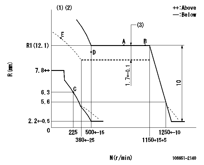
N:Pump speed
R:Rack position (mm)
(1)Beginning of damper spring operation: DL
(2)Boost compensator cancel stroke: BSL
(3)Boost compensator stroke
----------
DL=5.6-0.2mm BSL=2mm
----------
----------
DL=5.6-0.2mm BSL=2mm
----------
Timer adjustment

(1)Adjusting range
(2)Step response time
(N): Speed of the pump
(L): Load
(theta) Advance angle
(Srd1) Step response time 1
(Srd2) Step response time 2
1. Adjusting conditions for the variable timer
(1)Adjust the clearance between the pickup and the protrusion to L.
----------
L=1-0.2mm N2=800r/min C2=(8.8deg) t1=2.5--sec. t2=2.5--sec.
----------
N1=750++r/min P1=0kPa(0kgf/cm2) P2=392kPa(4kgf/cm2) C1=8.8+-0.3deg R01=0/4load R02=4/4load
----------
L=1-0.2mm N2=800r/min C2=(8.8deg) t1=2.5--sec. t2=2.5--sec.
----------
N1=750++r/min P1=0kPa(0kgf/cm2) P2=392kPa(4kgf/cm2) C1=8.8+-0.3deg R01=0/4load R02=4/4load
Speed control lever angle

F:Full speed
----------
----------
a=4deg+-5deg
----------
----------
a=4deg+-5deg
0000000901
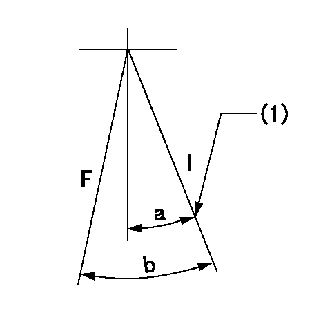
F:Full load
I:Idle
(1)Stopper bolt setting
----------
----------
a=21deg+-5deg b=36deg+-3deg
----------
----------
a=21deg+-5deg b=36deg+-3deg
Stop lever angle

N:Engine manufacturer's normal use
S:Stop the pump.
(1)Rack position = aa
(2)Stopper bolt setting
(3)Rack position bb
(4)Free (at delivery)
----------
aa=4.9-0.5mm bb=14mm
----------
a=25.5deg+-5deg b=(35.5deg) c=0deg+7deg-5deg
----------
aa=4.9-0.5mm bb=14mm
----------
a=25.5deg+-5deg b=(35.5deg) c=0deg+7deg-5deg
0000001501 MICRO SWITCH
Adjustment of the micro-switch
Adjust the bolt to obtain the following lever position when the micro-switch is ON.
(1)Speed N1
(2)Rack position Ra
----------
N1=325+-5r/min Ra=6mm
----------
----------
N1=325+-5r/min Ra=6mm
----------
0000001601 RACK SENSOR

V1:Supply voltage
V2f:Full side output voltage
V2i:Idle side output voltage
(A) Black
(B) Yellow
(C) Red
(D) Trimmer
(E): Shaft
(F) Nut
(G) Load lever
1. Load sensor adjustment
(1)Connect as shown in the above diagram and apply supply voltage V1.
(2)Hold the load lever (G) against the full side.
(3)Turn the shaft so that the voltage between (A) and (B) is V2.
(4)Hold the load lever (G) against the idle side.
(5)Adjust (D) so that the voltage between (A) and (B) is V2i.
(6)Repeat the above adjustments.
(7)Tighten the nut (F) at the point satisfying the standards.
(8)Hold the load lever against the full side stopper and the idle side stopper.
(9)At this time, confirm that the full side output voltage is V2f and the idle side output voltage is V2i.
----------
V1=5+-0.02V V2f=0.15+0.03V V2i=2.35-0.03V
----------
----------
V1=5+-0.02V V2f=0.15+0.03V V2i=2.35-0.03V
----------
Timing setting

(1)Pump vertical direction
(2)Coupling's key groove position at No 1 cylinder's beginning of injection
(3)-
(4)-
----------
----------
a=(7deg)
----------
----------
a=(7deg)
Information:
Start By:a. remove oil pumpb. remove timing gear coverc. remove flywheel housingd. remove pistons For more detail about removal of main bearings, see the topic "Remove & Install Crankshaft Main Bearings" in this module. 1. Check each bearing cap (1) for its location on the engine. Each cap has an arrow which is toward the front of the block and a number which gives the location of that cap. Keep each bearing with the correct cap.2. Remove bearing caps No. 2 through No. 6. Remove thrust plates from No. 4 upper bearing.3. Install one of the flywheel bolts in each end of the crankshaft. Fasten a hoist to the crankshaft as shown. Remove No. 1 and No. 7 main bearing caps. Remove the crankshaft. Weight of the crankshaft is 181 kg (400 lb).
Be careful not to damage the crankshaft journals when the crankshaft is removed.
4. Remove crankshaft gear (2) with Tooling (A).5. Remove dowel and pin from crankshaft with Tooling (B).Install Crankshaft
1. Install pin (1) in the crankshaft end until it is extended from the surface a distance of 6.4 0.5 mm (.25 .02 in).2. Install dowel (2) until it is extended from the surface a distance of 4.1 0.5 mm (.16 .02 in). 3. Heat crankshaft gear (3) to a maximum temperature of 232°C (450°F). Install gear (3) on the crankshaft with groove (4) in alignment with dowel (2).4. Make sure the upper main bearings are clean. Put clean oil on the upper main bearings and journals of the crankshaft. 5. Install one of the flywheel bolts in each end of the crankshaft. Fasten a hoist to the crankshaft and put it in position in the block.
Use care to prevent damage to the crankshaft journals. Make sure the "V" mark on the crankshaft gear is in alignment with the "V" mark on the idler gear.
For more detail about installation of main bearings, see Remove And Install Crankshaft Main Bearings.6. Check the bearing clearances with Plastigage.7. Put clean engine oil on the bolts for caps No. 1 and No. 7. Install No. 1 and No. 7 caps with the bolts finger tight. Make sure the arrows on the caps are toward the front of the block. 8. Install thrust plates (5) for the No. 4 upper main bearing. Install the thrust plates with the side that has identification "BLOCK SIDE" toward the cylinder block.9. Put clean oil on the bolts for caps No. 2 through No. 6. Install caps No. 2 through No. 6 with the bolts finger tight. Make sure the arrows are toward the front of the block.
Do not use an impact wrench to tighten the bolts the additional 120 degrees.
10. Tighten the cap bolts as follows:a. Tighten the bolts on the tab end of the caps first to a torque of 260 14 N m (190