Information injection-pump assembly
ZEXEL
106651-2130
1066512130

Rating:
Cross reference number
ZEXEL
106651-2130
1066512130
Zexel num
Bosch num
Firm num
Name
Calibration Data:
Adjustment conditions
Test oil
1404 Test oil ISO4113 or {SAEJ967d}
1404 Test oil ISO4113 or {SAEJ967d}
Test oil temperature
degC
40
40
45
Nozzle and nozzle holder
105780-8140
Bosch type code
EF8511/9A
Nozzle
105780-0000
Bosch type code
DN12SD12T
Nozzle holder
105780-2080
Bosch type code
EF8511/9
Opening pressure
MPa
17.2
Opening pressure
kgf/cm2
175
Injection pipe
Outer diameter - inner diameter - length (mm) mm 8-3-600
Outer diameter - inner diameter - length (mm) mm 8-3-600
Overflow valve opening pressure
kPa
157
123
191
Overflow valve opening pressure
kgf/cm2
1.6
1.25
1.95
Tester oil delivery pressure
kPa
157
157
157
Tester oil delivery pressure
kgf/cm2
1.6
1.6
1.6
Direction of rotation (viewed from drive side)
Right R
Right R
Injection timing adjustment
Direction of rotation (viewed from drive side)
Right R
Right R
Injection order
1-5-3-6-
2-4
Pre-stroke
mm
5.1
5.05
5.15
Beginning of injection position
Governor side NO.1
Governor side NO.1
Difference between angles 1
Cal 1-5 deg. 60 59.5 60.5
Cal 1-5 deg. 60 59.5 60.5
Difference between angles 2
Cal 1-3 deg. 120 119.5 120.5
Cal 1-3 deg. 120 119.5 120.5
Difference between angles 3
Cal 1-6 deg. 180 179.5 180.5
Cal 1-6 deg. 180 179.5 180.5
Difference between angles 4
Cyl.1-2 deg. 240 239.5 240.5
Cyl.1-2 deg. 240 239.5 240.5
Difference between angles 5
Cal 1-4 deg. 300 299.5 300.5
Cal 1-4 deg. 300 299.5 300.5
Injection quantity adjustment
Adjusting point
A
Rack position
11.6
Pump speed
r/min
1100
1100
1100
Average injection quantity
mm3/st.
138
132
144
Max. variation between cylinders
%
0
-4
4
Fixing the lever
*
Boost pressure
kPa
86.6
86.6
Boost pressure
mmHg
650
650
Standard for adjustment of the maximum variation between cylinders
*
Injection quantity adjustment_02
Adjusting point
B
Rack position
13
Pump speed
r/min
600
600
600
Average injection quantity
mm3/st.
156
154
158
Max. variation between cylinders
%
0
-3
3
Basic
*
Fixing the lever
*
Boost pressure
kPa
86.6
86.6
Boost pressure
mmHg
650
650
Standard for adjustment of the maximum variation between cylinders
*
Injection quantity adjustment_03
Adjusting point
C
Rack position
6.2+-0.5
Pump speed
r/min
250
250
250
Average injection quantity
mm3/st.
18.6
15.9
21.3
Max. variation between cylinders
%
0
-15
15
Fixing the rack
*
Boost pressure
kPa
0
0
0
Boost pressure
mmHg
0
0
0
Injection quantity adjustment_04
Adjusting point
D
Rack position
9.9
Pump speed
r/min
400
400
400
Average injection quantity
mm3/st.
93
87.4
98.6
Fixing the lever
*
Boost pressure
kPa
0
0
0
Boost pressure
mmHg
0
0
0
Injection quantity adjustment_05
Adjusting point
E
Rack position
11.4
Pump speed
r/min
400
400
400
Average injection quantity
mm3/st.
118
110
126
Fixing the lever
*
Boost pressure
kPa
28
28
28
Boost pressure
mmHg
210
210
210
Injection quantity adjustment_06
Adjusting point
F
Rack position
12.6
Pump speed
r/min
500
500
500
Average injection quantity
mm3/st.
150
142
158
Fixing the lever
*
Boost pressure
kPa
61.3
60
62.6
Boost pressure
mmHg
460
450
470
Boost compensator adjustment
Pump speed
r/min
600
600
600
Rack position
9.9
Boost pressure
kPa
6.7
5.4
9.4
Boost pressure
mmHg
50
40
70
Boost compensator adjustment_02
Pump speed
r/min
600
600
600
Rack position
11.4
Boost pressure
kPa
28
28
28
Boost pressure
mmHg
210
210
210
Boost compensator adjustment_03
Pump speed
r/min
600
600
600
Rack position
12.6
Boost pressure
kPa
61.3
60
62.6
Boost pressure
mmHg
460
450
470
Boost compensator adjustment_04
Pump speed
r/min
600
600
600
Rack position
13
Boost pressure
kPa
72
72
72
Boost pressure
mmHg
540
540
540
Timer adjustment
Pump speed
r/min
1000--
Advance angle
deg.
0
0
0
Remarks
Start
Start
Timer adjustment_02
Pump speed
r/min
950
Advance angle
deg.
0.5
Timer adjustment_03
Pump speed
r/min
1050
Advance angle
deg.
2.7
2.2
3.2
Timer adjustment_04
Pump speed
r/min
1150
Advance angle
deg.
6
5.5
6.5
Remarks
Finish
Finish
Test data Ex:
Governor adjustment
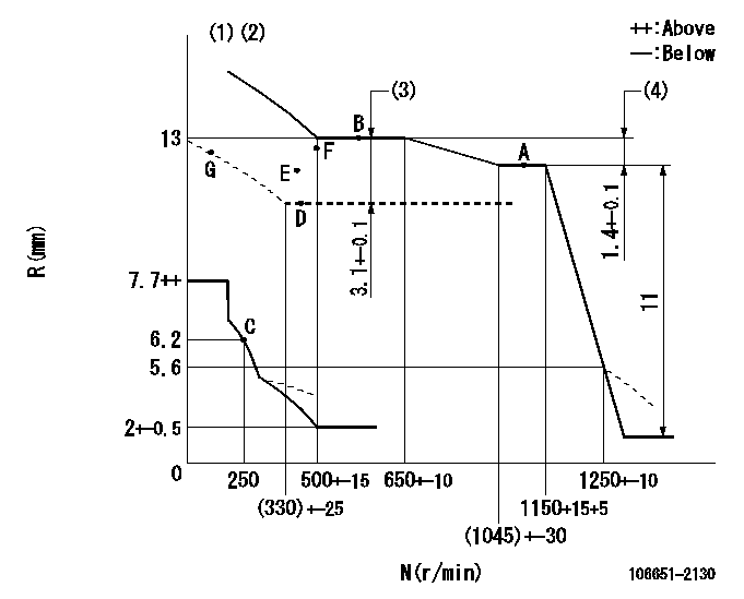
N:Pump speed
R:Rack position (mm)
(1)Beginning of damper spring operation: DL
(2)Boost compensator cancel stroke: BSL
(3)Boost compensator stroke
(4)Rack difference between N = N1 and N = N2
----------
DL=5.6-0.2mm BSL=3.4mm N1=600r/min N2=1100r/min
----------
----------
DL=5.6-0.2mm BSL=3.4mm N1=600r/min N2=1100r/min
----------
Speed control lever angle

F:Full speed
----------
----------
a=4deg+-5deg
----------
----------
a=4deg+-5deg
0000000901
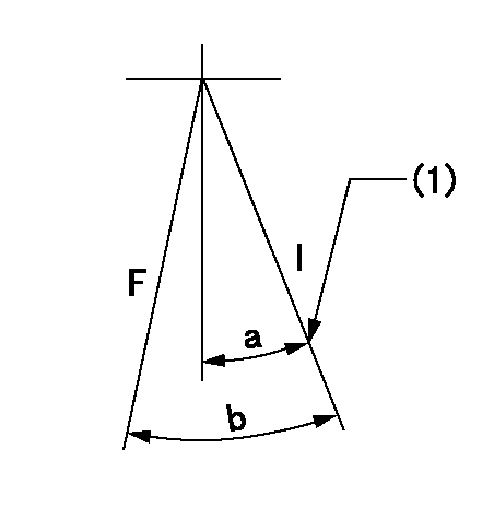
F:Full load
I:Idle
(1)Stopper bolt setting
----------
----------
a=21.5deg+-5deg b=39.5deg+-3deg
----------
----------
a=21.5deg+-5deg b=39.5deg+-3deg
Stop lever angle
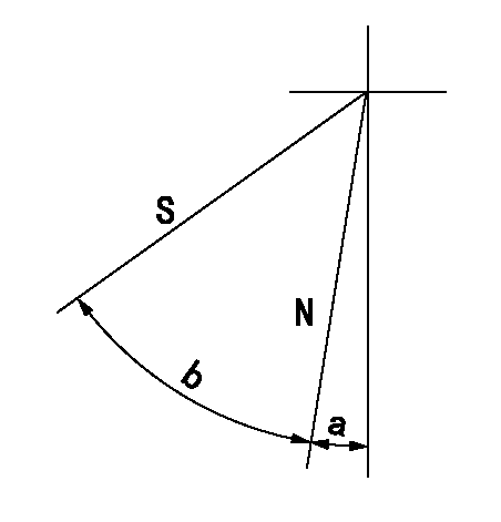
N:Pump normal
S:Stop the pump.
----------
----------
a=5deg+-5deg b=48.5deg+-5deg
----------
----------
a=5deg+-5deg b=48.5deg+-5deg
0000001501 MICRO SWITCH
Adjustment of the micro-switch
Adjust the bolt to obtain the following lever position when the micro-switch is ON.
(1)Speed N1
(2)Rack position Ra
----------
N1=310r/min Ra=6.2mm
----------
----------
N1=310r/min Ra=6.2mm
----------
Information:
Start By:a. remove oil pump 1. Check each connecting rod cap for its location on the crankshaft. Each cap must have a number (1) which is the same as the number on the connecting rod. Do not mix bearings.2. Turn the crankshaft until two of the pistons are at bottom center.3. Remove connecting rod caps (2). Remove the lower bearing from the connecting rod caps.4. Push the connecting rods away from the crankshaft and remove the upper bearings from the connecting rods.
Be careful not to damage the crankshaft journals. Do not turn the crankshaft while any of the connecting rod caps are removed.
5. Install the upper bearings in connecting rods. put clean engine oil on the bearings and on the crankshaft journals. Slowly pull the connecting rods on the crankshaft.6. Put clean oil on the lower bearings. Install the lower bearings in the connecting rod caps. Be sure tab (3) on the back of the bearings fits in the groove of the caps and connecting rods. 7. Check the bearing clearance with Plastigage (A) as follows:a. Put clean oil on the threads of bolts (4). Install caps (5), Tool (A) and nuts finger tight.b. Tighten each nut (6) to a torque of 80 8 N m (60 6 lb ft).c. Put a mark across the nuts and bolts. Tighten the nuts 120 degrees more. 8. Remove caps (5) and Plastigage (A). Make sure the connecting rod bearing caps are installed with their identification number in arrangement with the connecting rod number.
Do not use an impact wrench to tighten the nuts the additional 120 degrees.
9. Measure the thickness of the Plastigage to find the bearing clearance. the clearance for new bearings must be 0.071 to 0.168 mm (.0028 to .0066 in). The maximum clearance for used bearings is 0.25 mm (0.010 in).10. Install caps (5). Tighten nuts (6) to a torque of 80 8 N m (60 6 lb ft). Tighten the nuts 120 degrees more.11. Do Steps 1 through 10 for the other connecting rod bearings.End By:a. install oil pump