Information injection-pump assembly
ZEXEL
106651-2120
1066512120

Rating:
Cross reference number
ZEXEL
106651-2120
1066512120
Zexel num
Bosch num
Firm num
Name
Calibration Data:
Adjustment conditions
Test oil
1404 Test oil ISO4113 or {SAEJ967d}
1404 Test oil ISO4113 or {SAEJ967d}
Test oil temperature
degC
40
40
45
Nozzle and nozzle holder
105780-8140
Bosch type code
EF8511/9A
Nozzle
105780-0000
Bosch type code
DN12SD12T
Nozzle holder
105780-2080
Bosch type code
EF8511/9
Opening pressure
MPa
17.2
Opening pressure
kgf/cm2
175
Injection pipe
Outer diameter - inner diameter - length (mm) mm 8-3-600
Outer diameter - inner diameter - length (mm) mm 8-3-600
Overflow valve
132424-0620
Overflow valve opening pressure
kPa
157
123
191
Overflow valve opening pressure
kgf/cm2
1.6
1.25
1.95
Tester oil delivery pressure
kPa
157
157
157
Tester oil delivery pressure
kgf/cm2
1.6
1.6
1.6
Direction of rotation (viewed from drive side)
Right R
Right R
Injection timing adjustment
Direction of rotation (viewed from drive side)
Right R
Right R
Injection order
1-5-3-6-
2-4
Pre-stroke
mm
5.1
5.05
5.15
Beginning of injection position
Governor side NO.1
Governor side NO.1
Difference between angles 1
Cal 1-5 deg. 60 59.5 60.5
Cal 1-5 deg. 60 59.5 60.5
Difference between angles 2
Cal 1-3 deg. 120 119.5 120.5
Cal 1-3 deg. 120 119.5 120.5
Difference between angles 3
Cal 1-6 deg. 180 179.5 180.5
Cal 1-6 deg. 180 179.5 180.5
Difference between angles 4
Cyl.1-2 deg. 240 239.5 240.5
Cyl.1-2 deg. 240 239.5 240.5
Difference between angles 5
Cal 1-4 deg. 300 299.5 300.5
Cal 1-4 deg. 300 299.5 300.5
Injection quantity adjustment
Adjusting point
-
Rack position
13.3
Pump speed
r/min
600
600
600
Each cylinder's injection qty
mm3/st.
156
154
158
Basic
*
Fixing the rack
*
Standard for adjustment of the maximum variation between cylinders
*
Injection quantity adjustment_02
Adjusting point
F
Rack position
5.7+-0.5
Pump speed
r/min
500
500
500
Each cylinder's injection qty
mm3/st.
16.5
14
19
Fixing the rack
*
Standard for adjustment of the maximum variation between cylinders
*
Injection quantity adjustment_03
Adjusting point
A
Rack position
R1(13.3)
Pump speed
r/min
600
600
600
Average injection quantity
mm3/st.
156
155
157
Fixing the lever
*
Boost pressure
kPa
86.6
86.6
Boost pressure
mmHg
650
650
Injection quantity adjustment_04
Adjusting point
B
Rack position
11.9+-0.
5
Pump speed
r/min
1100
1100
1100
Average injection quantity
mm3/st.
138
135
141
Fixing the lever
*
Boost pressure
kPa
86.6
86.6
Boost pressure
mmHg
650
650
Injection quantity adjustment_05
Adjusting point
D
Rack position
10.3+-0.
5
Pump speed
r/min
400
400
400
Average injection quantity
mm3/st.
93
90.2
95.8
Fixing the lever
*
Boost pressure
kPa
0
0
0
Boost pressure
mmHg
0
0
0
Injection quantity adjustment_06
Adjusting point
E
Rack position
-
Pump speed
r/min
100
100
100
Average injection quantity
mm3/st.
110
70
150
Fixing the lever
*
Boost pressure
kPa
0
0
0
Boost pressure
mmHg
0
0
0
Injection quantity adjustment_07
Adjusting point
C
Rack position
6.3+-0.5
Pump speed
r/min
225
225
225
Each cylinder's injection qty
mm3/st.
18.6
15.9
21.3
Fixing the rack
*
Boost pressure
kPa
0
0
0
Boost pressure
mmHg
0
0
0
Remarks
(check)
(check)
Boost compensator adjustment
Pump speed
r/min
600
600
600
Rack position
(10.3)
Boost pressure
kPa
3.3
3.3
5.3
Boost pressure
mmHg
25
25
40
Boost compensator adjustment_02
Pump speed
r/min
600
600
600
Rack position
11.7
Boost pressure
kPa
28
28
28
Boost pressure
mmHg
210
210
210
Boost compensator adjustment_03
Pump speed
r/min
600
600
600
Rack position
12.9
Boost pressure
kPa
61.3
60
62.6
Boost pressure
mmHg
460
450
470
Boost compensator adjustment_04
Pump speed
r/min
600
600
600
Rack position
R1(13.3)
Boost pressure
kPa
72
72
72
Boost pressure
mmHg
540
540
540
Timer adjustment
Pump speed
r/min
1000--
Advance angle
deg.
0
0
0
Remarks
Start
Start
Timer adjustment_02
Pump speed
r/min
950
Advance angle
deg.
0.5
Timer adjustment_03
Pump speed
r/min
1050
Advance angle
deg.
2.7
2.2
3.2
Timer adjustment_04
Pump speed
r/min
1150
Advance angle
deg.
6
5.5
6.5
Remarks
Finish
Finish
Test data Ex:
Governor adjustment
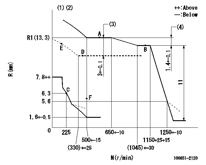
N:Pump speed
R:Rack position (mm)
(1)Beginning of damper spring operation: DL
(2)Boost compensator cancel stroke: BSL
(3)Boost compensator stroke
(4)Rack difference between N = N1 and N = N2
----------
DL=5.6-0.2mm BSL=3.4mm N1=600r/min N2=1100r/min
----------
----------
DL=5.6-0.2mm BSL=3.4mm N1=600r/min N2=1100r/min
----------
Speed control lever angle

F:Full speed
----------
----------
a=4deg+-5deg
----------
----------
a=4deg+-5deg
0000000901
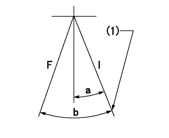
F:Full load
I:Idle
(1)Stopper bolt setting
----------
----------
a=21deg+-5deg b=42deg+-3deg
----------
----------
a=21deg+-5deg b=42deg+-3deg
Stop lever angle

N:Pump normal
S:Stop the pump.
(1)Rack position = aa
(2)Stopper bolt setting
(3)Rack position bb
(4)Free (at delivery)
----------
aa=4.9-0.5mm bb=15.6mm
----------
a=30.5deg+-5deg b=(35.5deg) c=0deg+7deg-5deg
----------
aa=4.9-0.5mm bb=15.6mm
----------
a=30.5deg+-5deg b=(35.5deg) c=0deg+7deg-5deg
0000001501 MICRO SWITCH
Adjustment of the micro-switch
Adjust the bolt to obtain the following lever position when the micro-switch is ON.
1. Inner side
(1)Speed N1
(2)Rack position Ra
2. Outside
(1)Speed N2
(2)Rack position Rb
----------
N1=325+-5r/min Ra=6mm N2=600r/min Rb=10.7mm
----------
----------
N1=325+-5r/min Ra=6mm N2=600r/min Rb=10.7mm
----------
Information:
Start By:a. remove valve covers
Typical Example1. Use Tool (A) to loosen the nuts and remove fuel lines (2).2. Disconnect fuel lines (1) from the valve cover base adapters.
Put protection caps (5F-2807) and plugs (2F-2990) on the fuel line openings to keep dirt and foreign material out of the fuel system.
3. Remove locks (3) and fuel line adapters (4) from the valve cover bases for clearance to remove the rocker shaft bolts. 4. Remove bolts (5) and rocker shaft assemblies (6) from the cylinder head. 5. Remove push rods (7) from the cylinder heads.6. Put identification on each valve bridge as to its location. Remove valve bridges (8) from the cylinder heads.Install Rocker Shaft Assemblies
1. Put clean engine oil on the bridge dowels, push rods (2) and inside bridges (1). Install bridges (1) and push rods (2) in the correct positions. 2. Push straight down on the top contact surface of valve bridge (1) with a force of 4 to 45 N (1 to 10 lb). Turn the adjustment screw clockwise until contact is made with the valve stem. Turn the adjustment screw 20 to 30 degrees more to keep bridge (1) straight on the dowel. Hold the adjustment screw in this position and tighten the locknut to a torque of 28 4 N m (22 3 lb ft). 3. Put rocker shaft assembly (3) in position on the cylinder head. Make sure the adjustment screws in the rocker arms are correctly engaged with the push rods. 4. Put clean engine oil on the threads of the bolts and install the bolts to hold rocker shaft assembly. Tighten the bolts as follows:a. Tighten bolts 1 through 6 in number sequence shown to a torque of 270 25 N m (200 20 lb ft).b. Tighten bolts 1 through 6 in number sequence shown to a torque of 447 20 N m (330 15 lb ft).c. Tighten bolts 1 through 6 in number sequence shown again to a torque of 447 20 N m (330 15 lb ft). 5. Put clean engine oil on the O-ring seals and install fuel line adapters (5), the washers, spaces, locks and nuts (4). Tighten nuts (4) to a torque of 14 3 N m (10 2 lb ft) 6. Install fuel lines (7) and connect fuel lines (6) to the fuel line adapters. Use Tool (A) and tighten the nuts for fuel lines (7). Tighten all fuel line nuts to a torque of 40 7 N m (30 5 lb ft).7. Make an adjustment of the valves to have a clearance of 0.38 mm (.015 in) for intake and 0.76 mm (.030 in) for exhaust. See Valve Clearance Setting in Testing And Adjusting.End By:a. install valve covers Disassemble Rocker Shaft Assemblies
Start By:a. remove rocker shaft assemblies 1. Remove retainer (1) from the end of the shaft.2. Remove the washers and rocker arm (2). 3. Use Tool (A) to remove the pin that