Information injection-pump assembly
ZEXEL
106651-2110
1066512110

Rating:
Cross reference number
ZEXEL
106651-2110
1066512110
Zexel num
Bosch num
Firm num
Name
Calibration Data:
Adjustment conditions
Test oil
1404 Test oil ISO4113 or {SAEJ967d}
1404 Test oil ISO4113 or {SAEJ967d}
Test oil temperature
degC
40
40
45
Nozzle and nozzle holder
105780-8140
Bosch type code
EF8511/9A
Nozzle
105780-0000
Bosch type code
DN12SD12T
Nozzle holder
105780-2080
Bosch type code
EF8511/9
Opening pressure
MPa
17.2
Opening pressure
kgf/cm2
175
Injection pipe
Outer diameter - inner diameter - length (mm) mm 8-3-600
Outer diameter - inner diameter - length (mm) mm 8-3-600
Overflow valve opening pressure
kPa
157
123
191
Overflow valve opening pressure
kgf/cm2
1.6
1.25
1.95
Tester oil delivery pressure
kPa
157
157
157
Tester oil delivery pressure
kgf/cm2
1.6
1.6
1.6
Direction of rotation (viewed from drive side)
Right R
Right R
Injection timing adjustment
Direction of rotation (viewed from drive side)
Right R
Right R
Injection order
1-5-3-6-
2-4
Pre-stroke
mm
5.1
5.05
5.15
Beginning of injection position
Governor side NO.1
Governor side NO.1
Difference between angles 1
Cal 1-5 deg. 60 59.5 60.5
Cal 1-5 deg. 60 59.5 60.5
Difference between angles 2
Cal 1-3 deg. 120 119.5 120.5
Cal 1-3 deg. 120 119.5 120.5
Difference between angles 3
Cal 1-6 deg. 180 179.5 180.5
Cal 1-6 deg. 180 179.5 180.5
Difference between angles 4
Cyl.1-2 deg. 240 239.5 240.5
Cyl.1-2 deg. 240 239.5 240.5
Difference between angles 5
Cal 1-4 deg. 300 299.5 300.5
Cal 1-4 deg. 300 299.5 300.5
Injection quantity adjustment
Adjusting point
-
Rack position
11.8
Pump speed
r/min
700
700
700
Each cylinder's injection qty
mm3/st.
134.4
131.4
137.4
Basic
*
Fixing the rack
*
Standard for adjustment of the maximum variation between cylinders
*
Injection quantity adjustment_02
Adjusting point
F
Rack position
5.7+-0.5
Pump speed
r/min
500
500
500
Each cylinder's injection qty
mm3/st.
16.5
14
19
Fixing the rack
*
Standard for adjustment of the maximum variation between cylinders
*
Injection quantity adjustment_03
Adjusting point
A
Rack position
R1(11.8)
Pump speed
r/min
700
700
700
Average injection quantity
mm3/st.
134.4
133.4
135.4
Fixing the lever
*
Boost pressure
kPa
60
60
Boost pressure
mmHg
450
450
Injection quantity adjustment_04
Adjusting point
B
Rack position
R1(11.8)
Pump speed
r/min
1100
1100
1100
Average injection quantity
mm3/st.
133.4
129.4
137.4
Difference in delivery
mm3/st.
8
8
8
Fixing the lever
*
Boost pressure
kPa
60
60
Boost pressure
mmHg
450
450
Injection quantity adjustment_05
Adjusting point
D
Rack position
10.9+-0.
5
Pump speed
r/min
400
400
400
Average injection quantity
mm3/st.
110.5
106.5
114.5
Fixing the lever
*
Boost pressure
kPa
0
0
0
Boost pressure
mmHg
0
0
0
Injection quantity adjustment_06
Adjusting point
E
Rack position
12.5+-0.
5
Pump speed
r/min
100
100
100
Average injection quantity
mm3/st.
140
120
160
Fixing the lever
*
Boost pressure
kPa
0
0
0
Boost pressure
mmHg
0
0
0
Injection quantity adjustment_07
Adjusting point
C
Rack position
6.3+-0.5
Pump speed
r/min
225
225
225
Each cylinder's injection qty
mm3/st.
18.6
15.9
21.3
Fixing the rack
*
Boost pressure
kPa
0
0
0
Boost pressure
mmHg
0
0
0
Remarks
(check)
(check)
Boost compensator adjustment
Pump speed
r/min
600
600
600
Rack position
(10.9)
Boost pressure
kPa
21.3
21.3
21.3
Boost pressure
mmHg
160
160
160
Boost compensator adjustment_02
Pump speed
r/min
600
600
600
Rack position
11.3
Boost pressure
kPa
32
30.7
33.3
Boost pressure
mmHg
240
230
250
Boost compensator adjustment_03
Pump speed
r/min
600
600
600
Rack position
R1(11.8)
Boost pressure
kPa
45.3
38.6
52
Boost pressure
mmHg
340
290
390
Timer adjustment
Pump speed
r/min
1000--
Advance angle
deg.
0
0
0
Remarks
Start
Start
Timer adjustment_02
Pump speed
r/min
950
Advance angle
deg.
0.5
Timer adjustment_03
Pump speed
r/min
1050
Advance angle
deg.
2.7
2.2
3.2
Timer adjustment_04
Pump speed
r/min
1150
Advance angle
deg.
6
5.5
6.5
Remarks
Finish
Finish
Test data Ex:
Governor adjustment
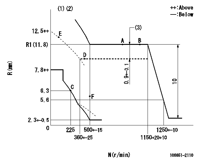
N:Pump speed
R:Rack position (mm)
(1)Beginning of damper spring operation: DL
(2)Boost compensator cancel stroke: BSL
(3)Boost compensator stroke
----------
DL=5.6-0.2mm BSL=1.2mm
----------
----------
DL=5.6-0.2mm BSL=1.2mm
----------
Speed control lever angle

F:Full speed
----------
----------
a=4deg+-5deg
----------
----------
a=4deg+-5deg
0000000901
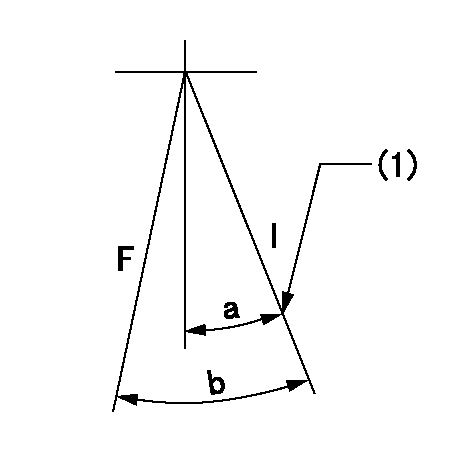
F:Full load
I:Idle
(1)Stopper bolt setting
----------
----------
a=21deg+-5deg b=35deg+-3deg
----------
----------
a=21deg+-5deg b=35deg+-3deg
Stop lever angle

N:Pump normal
S:Stop the pump.
(1)Rack position = aa
(2)Stopper bolt setting
(3)Rack position bb
(4)Free (at delivery)
----------
aa=4.9-0.5mm bb=14mm
----------
a=25.5deg+-5deg b=(35.5deg) c=0deg+7deg-5deg
----------
aa=4.9-0.5mm bb=14mm
----------
a=25.5deg+-5deg b=(35.5deg) c=0deg+7deg-5deg
0000001501 MICRO SWITCH
Adjustment of the micro-switch
Adjust the bolt to obtain the following lever position when the micro-switch is ON.
(1)Speed N1
(2)Rack position Ra
----------
N1=325+-5r/min Ra=6mm
----------
----------
N1=325+-5r/min Ra=6mm
----------
Information:
Start By:a. remove valve cover 1. Remove the cover from the flywheel housing and install Tool (A). Turn the crankshaft with Tool (A) until there is no pressure on rocker arm (2).2. Use Tool (B) as shown to move the rocker arm away from push rod (1). Remove push rod (1). 3. Install Tool (C) on the valve lifter. Remove valve lifter (3) from the block. 4. Remove spring guide (4) from the valve lifter.5. Do Steps 1 through 4 again for the other valve lifters and push rods if necessary.Install Valve Lifters & Push Rods
Any time the valve lifter is removed from the machine, a new spring guide must be installed on the valve lifter.1. Install spring guide (1) on valve lifter (2). 2. Put the valve lifter in position on Tool (A) as shown. Make sure spring guide (1) is in position in the groove (slot) in the valve lifter as shown. 3. Use a soft hammer to install Tool (B) over spring guide (1). Make sure the groove in Tool (B) is in alignment with spring guide (1). 4. Put clean engine oil on valve lifter (2). Use Tool (B) to install the valve lifter in the engine block. Make sure the end of the spring guide is in alignment with the small hole in the block.5. When the valve lifter is in position in the block, use Tool (C) to push the valve lifter off of Tool (C). 6. Use Tool (E) to turn the crankshaft to make sure there is not pressure on the push rods and rocker arms.7. Put push rod (3) in position in the block. Use Tool (D) to move rocker arm (4) away from the push rod far enough to put push rod (3) in position under the rocker arm.End By:a. install valve cover
Any time the valve lifter is removed from the machine, a new spring guide must be installed on the valve lifter.1. Install spring guide (1) on valve lifter (2). 2. Put the valve lifter in position on Tool (A) as shown. Make sure spring guide (1) is in position in the groove (slot) in the valve lifter as shown. 3. Use a soft hammer to install Tool (B) over spring guide (1). Make sure the groove in Tool (B) is in alignment with spring guide (1). 4. Put clean engine oil on valve lifter (2). Use Tool (B) to install the valve lifter in the engine block. Make sure the end of the spring guide is in alignment with the small hole in the block.5. When the valve lifter is in position in the block, use Tool (C) to push the valve lifter off of Tool (C). 6. Use Tool (E) to turn the crankshaft to make sure there is not pressure on the push rods and rocker arms.7. Put push rod (3) in position in the block. Use Tool (D) to move rocker arm (4) away from the push rod far enough to put push rod (3) in position under the rocker arm.End By:a. install valve cover