Information injection-pump assembly
ZEXEL
106651-0310
1066510310
Rating:
Cross reference number
ZEXEL
106651-0310
1066510310
Zexel num
Bosch num
Firm num
Name
Calibration Data:
Adjustment conditions
Test oil
1404 Test oil ISO4113 or {SAEJ967d}
1404 Test oil ISO4113 or {SAEJ967d}
Test oil temperature
degC
40
40
45
Nozzle and nozzle holder
105780-8140
Bosch type code
EF8511/9A
Nozzle
105780-0000
Bosch type code
DN12SD12T
Nozzle holder
105780-2080
Bosch type code
EF8511/9
Opening pressure
MPa
17.2
Opening pressure
kgf/cm2
175
Injection pipe
Outer diameter - inner diameter - length (mm) mm 8-3-600
Outer diameter - inner diameter - length (mm) mm 8-3-600
Overflow valve
132424-0620
Overflow valve opening pressure
kPa
157
123
191
Overflow valve opening pressure
kgf/cm2
1.6
1.25
1.95
Tester oil delivery pressure
kPa
157
157
157
Tester oil delivery pressure
kgf/cm2
1.6
1.6
1.6
Direction of rotation (viewed from drive side)
Right R
Right R
Injection timing adjustment
Direction of rotation (viewed from drive side)
Right R
Right R
Injection order
1-4-2-6-
3-5
Pre-stroke
mm
3.65
3.6
3.7
Beginning of injection position
Drive side NO.1
Drive side NO.1
Difference between angles 1
Cal 1-4 deg. 60 59.5 60.5
Cal 1-4 deg. 60 59.5 60.5
Difference between angles 2
Cyl.1-2 deg. 120 119.5 120.5
Cyl.1-2 deg. 120 119.5 120.5
Difference between angles 3
Cal 1-6 deg. 180 179.5 180.5
Cal 1-6 deg. 180 179.5 180.5
Difference between angles 4
Cal 1-3 deg. 240 239.5 240.5
Cal 1-3 deg. 240 239.5 240.5
Difference between angles 5
Cal 1-5 deg. 300 299.5 300.5
Cal 1-5 deg. 300 299.5 300.5
Injection quantity adjustment
Adjusting point
A
Rack position
10.7+-0.
5
Pump speed
r/min
850
850
850
Average injection quantity
mm3/st.
99.5
97.5
101.5
Max. variation between cylinders
%
0
-4
4
Fixing the lever
*
Injection quantity adjustment_02
Adjusting point
B
Rack position
10.7
Pump speed
r/min
750
750
750
Average injection quantity
mm3/st.
97
95
99
Max. variation between cylinders
%
0
-4
4
Basic
*
Fixing the lever
*
Injection quantity adjustment_03
Adjusting point
C
Rack position
7+-0.5
Pump speed
r/min
300
300
300
Average injection quantity
mm3/st.
12.5
10.8
14.2
Max. variation between cylinders
%
0
-10
10
Fixing the rack
*
Injection quantity adjustment_04
Adjusting point
D
Rack position
-
Pump speed
r/min
100
100
100
Average injection quantity
mm3/st.
65
60
70
Fixing the lever
*
Rack limit
*
Timer adjustment
Pump speed
r/min
300+-50
Advance angle
deg.
0
0
0
Remarks
Start
Start
Timer adjustment_02
Pump speed
r/min
500+40-1
0
Advance angle
deg.
1.35
0.85
1.55
Timer adjustment_03
Pump speed
r/min
700+40-1
0
Advance angle
deg.
2.85
2.35
3.05
Timer adjustment_04
Pump speed
r/min
900+40-1
0
Advance angle
deg.
4.4
3.8
4.6
Timer adjustment_05
Pump speed
r/min
-
Advance angle
deg.
6.1
6.1
6.1
Remarks
Measure the actual speed, stop
Measure the actual speed, stop
Test data Ex:
Governor adjustment
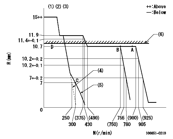
N:Pump speed
R:Rack position (mm)
(1)Target notch: K
(2)Tolerance for racks not indicated: +-0.05mm.
(3)Solenoid operation confirmation: Set the speed control lever in the full speed position. At pump speed N1 when the solenoid is operated, confirm that the idle rack position is R1 or less.
(4)At pump speed N2, set the control lever stopper bolt (minimum speed setting) so that the rack position is R2.
(5)Set idle sub-spring
(6)RACK LIMIT
----------
K=5 N1=100r/min R1=-1mm N2=250r/min R2=7mm
----------
----------
K=5 N1=100r/min R1=-1mm N2=250r/min R2=7mm
----------
Speed control lever angle
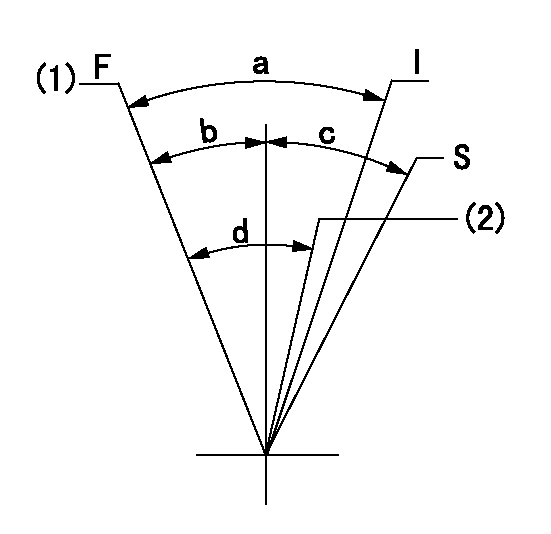
F:Full speed
I:Idle
S:Stop
(1)Set the pump speed at aa. ( At delivery )
(2)Pump speed = bb
----------
aa=905r/min bb=755r/min
----------
a=29.5deg+-5deg b=2.5deg+-5deg c=(32deg+-3deg) d=7.5deg+-5deg
----------
aa=905r/min bb=755r/min
----------
a=29.5deg+-5deg b=2.5deg+-5deg c=(32deg+-3deg) d=7.5deg+-5deg
Stop lever angle
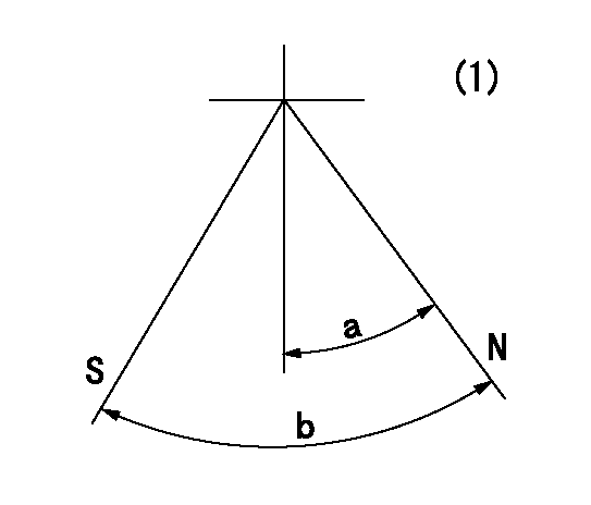
N:Pump normal
S:Stop the pump.
(1)No return spring
----------
----------
a=(29deg) b=(47deg)
----------
----------
a=(29deg) b=(47deg)
Information:
Start By:a. remove crankshaft rear seal and wear sleeveb. remove oil pan 1. Fasten a hoist to implement pump (1) and remove the pump (if equipped). The weight of implement pump (1) is 29 kg (75 lb). 2. Remove plates (2).3. Remove pump drives (3) (if equipped) with Tool (A) and a hoist. The weight of each pump drive is 29 kg (65 lb). 4. Remove plate (4). 5. Remove starting motor (5) and disconnect oil supply line (6) at the flywheel housing. 6. Remove engine rear supports (7). 7. Remove turbocharger oil supply line (8) and bracket (9). 8. Remove top section of turbocharger heat shield (10). 9. Remove turbocharger drain line (11) and elbow (12). 10. Remove plate (13). 11. Remove bolts (14) and the remainder of the bolts which hold bracket (15) to the engine and remove bracket (15). 12. Use Tooling (A) and fasten a hoist to flywheel housing (16). Remove the bolts that hold flywheel housing (16) in position and pull flywheel housing off the dowels and remove it. The weight of the flywheel housing is 191 kg (425 lb).13. Put the flywheel housing in the position shown. 14. Remove bolts (17) from shafts (19).
Bearings (20) can fall out of gears (18) when the gears are removed from the flywheel housing.
15. Remove gears (18) from the flywheel housing. 16. Remove shafts (19), bearing cones (22), spacers (21) and bearing cones (20) from gears (18). 17. If necessary, remove bearing cups (23) and (25), spacers (24) and the snap rings from gears (18). The bearing cups will have damage after removal. Use new parts for replacement.Install Flywheel Housing
1. Install the snap rings in the groove in idler gear (2).2. Install the spacers for bearing cups (1) in gears (2) from the side of gears (2) that have the part number. Make sure the notches in the spacers are toward the snap rings. The snap rings are not in the center of the gear bores. The spacers must be installed in the gear bores that have the longer measurement from the snap ring to the surface of the gear.3. Lower the temperature of bearing cups (1) and install them in gears (2) until they make contact with the spacers. 4. Put the flywheel housing in the position shown and install bearing cones (3). 5. Put idler gears (2) in position on the bearing cones. Make sure the side of gears (2) with the part number is toward the flywheel housing. 6. Put spacer (4) on the inner race of the bearing cone. 7. Install bearing cones (5) in the gears. 8. Install shafts (6) and the bolts to hold them.
Put the No. 1 piston at top center to make an alignment of the timing marks on the crankshaft rear gear (9) with the balancer gear (8). Failure to follow this procedure can cause damage to the engine.
9. Clean the front face of the flywheel housing and the rear face of the cylinder block. Make