Information injection-pump assembly
ZEXEL
106651-0250
1066510250
NISSAN-DIESEL
1670096104
1670096104
Rating:
Cross reference number
ZEXEL
106651-0250
1066510250
NISSAN-DIESEL
1670096104
1670096104
Zexel num
Bosch num
Firm num
Name
Calibration Data:
Adjustment conditions
Test oil
1404 Test oil ISO4113 or {SAEJ967d}
1404 Test oil ISO4113 or {SAEJ967d}
Test oil temperature
degC
40
40
45
Nozzle and nozzle holder
105780-8140
Bosch type code
EF8511/9A
Nozzle
105780-0000
Bosch type code
DN12SD12T
Nozzle holder
105780-2080
Bosch type code
EF8511/9
Opening pressure
MPa
17.2
Opening pressure
kgf/cm2
175
Injection pipe
Outer diameter - inner diameter - length (mm) mm 8-3-600
Outer diameter - inner diameter - length (mm) mm 8-3-600
Tester oil delivery pressure
kPa
157
157
157
Tester oil delivery pressure
kgf/cm2
1.6
1.6
1.6
Direction of rotation (viewed from drive side)
Right R
Right R
Injection timing adjustment
Direction of rotation (viewed from drive side)
Right R
Right R
Injection order
1-4-2-6-
3-5
Pre-stroke
mm
3.65
3.6
3.7
Beginning of injection position
Drive side NO.1
Drive side NO.1
Difference between angles 1
Cal 1-4 deg. 60 59.5 60.5
Cal 1-4 deg. 60 59.5 60.5
Difference between angles 2
Cyl.1-2 deg. 120 119.5 120.5
Cyl.1-2 deg. 120 119.5 120.5
Difference between angles 3
Cal 1-6 deg. 180 179.5 180.5
Cal 1-6 deg. 180 179.5 180.5
Difference between angles 4
Cal 1-3 deg. 240 239.5 240.5
Cal 1-3 deg. 240 239.5 240.5
Difference between angles 5
Cal 1-5 deg. 300 299.5 300.5
Cal 1-5 deg. 300 299.5 300.5
Injection quantity adjustment
Adjusting point
A
Rack position
11
Pump speed
r/min
750
750
750
Average injection quantity
mm3/st.
108.6
106.6
110.6
Max. variation between cylinders
%
0
-4
4
Basic
*
Fixing the lever
*
Injection quantity adjustment_02
Adjusting point
B
Rack position
11
Pump speed
r/min
1000
1000
1000
Average injection quantity
mm3/st.
110.6
107.6
113.6
Max. variation between cylinders
%
0
-4
4
Fixing the lever
*
Injection quantity adjustment_03
Adjusting point
C
Rack position
11
Pump speed
r/min
1150
1150
1150
Average injection quantity
mm3/st.
115.4
112.4
118.4
Max. variation between cylinders
%
0
-4
4
Fixing the lever
*
Injection quantity adjustment_04
Adjusting point
D
Rack position
11
Pump speed
r/min
400
400
400
Average injection quantity
mm3/st.
94.2
91.2
97.2
Max. variation between cylinders
%
0
-6
6
Fixing the lever
*
Injection quantity adjustment_05
Adjusting point
E
Rack position
7.2+-0.5
Pump speed
r/min
200
200
200
Average injection quantity
mm3/st.
10.3
9.3
11.3
Max. variation between cylinders
%
0
-10
10
Fixing the rack
*
Timer adjustment
Pump speed
r/min
300+-50
Advance angle
deg.
0
0
0
Remarks
Start
Start
Timer adjustment_02
Pump speed
r/min
500+40-1
0
Advance angle
deg.
1.35
1.05
1.55
Timer adjustment_03
Pump speed
r/min
700+40-1
0
Advance angle
deg.
2.85
2.35
3.05
Timer adjustment_04
Pump speed
r/min
900+40-1
0
Advance angle
deg.
4.4
3.8
4.6
Timer adjustment_05
Pump speed
r/min
1100+50
Advance angle
deg.
6.1
5.7
6.5
Remarks
Finish
Finish
Test data Ex:
Governor adjustment
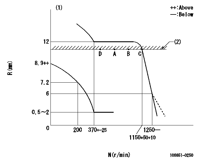
N:Pump speed
R:Rack position (mm)
(1)Beginning of damper spring operation: DL
(2)RACK LIMIT: RAL
----------
DL=6-0.2mm RAL=11mm
----------
----------
DL=6-0.2mm RAL=11mm
----------
0000000901
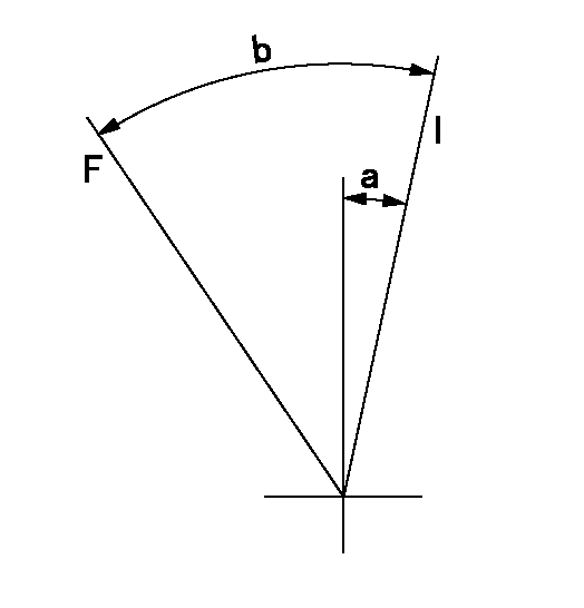
F:Full load
I:Idle
----------
----------
a=13.5deg+-5deg b=22deg+-3deg
----------
----------
a=13.5deg+-5deg b=22deg+-3deg
Stop lever angle
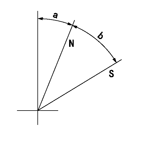
N:Pump normal
S:Stop the pump.
----------
----------
a=4deg+-5deg b=34deg+-3deg
----------
----------
a=4deg+-5deg b=34deg+-3deg
Information:
1. Disconnect hose (1) at governor control cylinder (2).2. Remove pin (4).3. Remove governor control cylinder (2).4. Note the position of linkage (3) in the lever, and remove linkage (3). The following steps are for installation of the governor control cylinder.5. Adjust linkage (3) so the distance between rod end centers is 84.07 mm (3.309 in).6. Install linkage (3) in its original position in the lever.7. Be sure lever (5) on the governor shaft is at 15 degrees from vertical (CW when viewed from the left side of the machine) with engine at low idle.8. Install control cylinder (2). Install pin (4) through link (3) and lever (5).9. Connect hose (1) to governor control cylinder (2).10. Adjust linkage (3) so lever (5) is at low idle when governor control cylinder is fully retracted.Disassemble & Assemble Governor Control Cylinder
Start By:a. remove governor control cylinder 1. Remove cover (1).
A spring force of 44.5 N (10 lb) will be released when the bolt that holds piston (8) is removed. Hold the components of the governor control cylinder to prevent unexpected movement of components and personal injury.
2. Remove the bolt that holds piston (6), and remove the piston and springs.3. Remove O-ring seal (2) and sleeve (5).4. Remove seals (3) and (4) from piston (6). The following steps are for the assembly of the governor control cylinder.5. Install lip-type seal (3) and "T" seal on the piston (6). Install the lip-type seal with the lip facing the cylinder pressure source.6. Install shell (5) in the air chamber body.7. Put 5P-0960 Multipurpose Grease inside the shell.8. Carefully install piston (6) and springs into the air chamber body.9. Install the bolt to hold the piston.10. Install O-ring seal (2) and cover (1).End By:a. install governor control cylinder