Information injection-pump assembly
BOSCH
9 400 612 374
9400612374
ZEXEL
106471-2031
1064712031
MITSUBISHI-HEAV
3636510111
3636510111
Rating:
Service parts 106471-2031 INJECTION-PUMP ASSEMBLY:
1.
_
7.
COUPLING PLATE
8.
_
9.
_
10.
NOZZLE AND HOLDER ASSY
11.
Nozzle and Holder
12.
Open Pre:MPa(Kqf/cm2)
21.6{220}
15.
NOZZLE SET
Include in #1:
106471-2031
as INJECTION-PUMP ASSEMBLY
Cross reference number
BOSCH
9 400 612 374
9400612374
ZEXEL
106471-2031
1064712031
MITSUBISHI-HEAV
3636510111
3636510111
Zexel num
Bosch num
Firm num
Name
9 400 612 374
3636510111 MITSUBISHI-HEAV
INJECTION-PUMP ASSEMBLY
S4B K 14BW INJECTION PUMP ASSY PE4P,4PD PE
S4B K 14BW INJECTION PUMP ASSY PE4P,4PD PE
Calibration Data:
Adjustment conditions
Test oil
1404 Test oil ISO4113 or {SAEJ967d}
1404 Test oil ISO4113 or {SAEJ967d}
Test oil temperature
degC
40
40
45
Nozzle and nozzle holder
105780-8140
Bosch type code
EF8511/9A
Nozzle
105780-0000
Bosch type code
DN12SD12T
Nozzle holder
105780-2080
Bosch type code
EF8511/9
Opening pressure
MPa
17.2
Opening pressure
kgf/cm2
175
Injection pipe
Outer diameter - inner diameter - length (mm) mm 8-3-600
Outer diameter - inner diameter - length (mm) mm 8-3-600
Overflow valve opening pressure
kPa
157
157
157
Overflow valve opening pressure
kgf/cm2
1.6
1.6
1.6
Tester oil delivery pressure
kPa
157
157
157
Tester oil delivery pressure
kgf/cm2
1.6
1.6
1.6
Direction of rotation (viewed from drive side)
Right R
Right R
Injection timing adjustment
Direction of rotation (viewed from drive side)
Right R
Right R
Injection order
1-3-4-2
Pre-stroke
mm
3.7
3.65
3.75
Beginning of injection position
Governor side NO.1
Governor side NO.1
Difference between angles 1
Cal 1-3 deg. 90 89.5 90.5
Cal 1-3 deg. 90 89.5 90.5
Difference between angles 2
Cal 1-4 deg. 180 179.5 180.5
Cal 1-4 deg. 180 179.5 180.5
Difference between angles 3
Cyl.1-2 deg. 270 269.5 270.5
Cyl.1-2 deg. 270 269.5 270.5
Injection quantity adjustment
Adjusting point
A
Rack position
11.3
Pump speed
r/min
1150
1150
1150
Average injection quantity
mm3/st.
178
171
185
Max. variation between cylinders
%
0
-3
3
Basic
*
Fixing the lever
*
Injection quantity adjustment_02
Adjusting point
B
Rack position
5.5+-0.5
Pump speed
r/min
250
250
250
Average injection quantity
mm3/st.
25.5
22.5
28.5
Max. variation between cylinders
%
0
-10
10
Fixing the rack
*
Injection quantity adjustment_03
Adjusting point
C
Rack position
-
Pump speed
r/min
100
100
100
Average injection quantity
mm3/st.
224
224
234
Fixing the lever
*
Rack limit
*
Timer adjustment
Pump speed
r/min
450--
Advance angle
deg.
0
0
0
Remarks
Start
Start
Timer adjustment_02
Pump speed
r/min
400
Advance angle
deg.
0.5
Timer adjustment_03
Pump speed
r/min
500
Advance angle
deg.
0.9
Timer adjustment_04
Pump speed
r/min
700
Advance angle
deg.
1.2
0.7
1.7
Timer adjustment_05
Pump speed
r/min
850
Advance angle
deg.
2
1.5
2.5
Timer adjustment_06
Pump speed
r/min
1150
Advance angle
deg.
4
3.5
4.5
Remarks
Finish
Finish
Test data Ex:
Governor adjustment
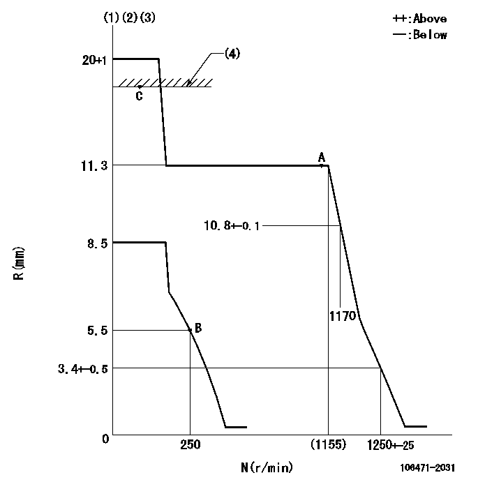
N:Pump speed
R:Rack position (mm)
(1)Target notch: K
(2)Tolerance for racks not indicated: +-0.05mm.
(3)Idle spring not operating.
(4)RACK LIMIT
----------
K=16
----------
----------
K=16
----------
Speed control lever angle

F:Full speed
I:Idle
S:Stop
----------
----------
a=18deg+-5deg b=32deg+-3deg c=40deg+-5deg
----------
----------
a=18deg+-5deg b=32deg+-3deg c=40deg+-5deg
Stop lever angle

N:Pump normal
S:Stop the pump.
(1)Normal
----------
----------
a=50deg+-5deg b=53deg+-5deg
----------
----------
a=50deg+-5deg b=53deg+-5deg
Information:
Customer Specified Parameters
Customer Specified Parameters allow a customer to restrict how a operator operates the vehicle. Some parameters may affect engine operation in ways that the uninformed operator does not expect. These parameters may lead to power and/or performance complaints, even when the engine is operating to specifications. If the NEXG4512 Customer Parameter Configuration Aid, Service Program Module (Optional Electronic Service Tool) is installed in an ECAP equipped with the 8C9700 Rechargeable Portable Printer, a list of Customer Specified Parameters can be read from the ECM and printed out.Customer parameters may be changed repeatedly as a customer changes his operation. Customer Passwords are required to change these parameters.The following is a brief description of the Customer Specified Parameters. Along with each, are the minimum and maximum values for the parameter and the default value. If a feature is not used, the parameter should be programmed to the default value.Engine Parameters
Rating Number:Number of rating within the horsepower family. The personality module defines the horsepower family (such as 325 hp). This number defines which rating is used (such as 325 hp at 1900 rpm or 325 hp at 2100 rpm) within the family. Top Engine Limit (TEL):Maximum engine rpm when the engine is under load. The engine will still achieve rated rpm under no load.Minimum ... Map (Rating) DependentMaximum ... Rated rpm + 20 rpmDefault ... Rated rpm + 20 rpm Top engine limiting with the 3176 has no governor overrun (it is an isochronous setting with no droop). Low Idle RPM:Minimum engine rpm.Minimum ... 600 rpmMaximum ... 750 rpmDefault ... 700 rpm Vehicle ID:Identification of vehicle assigned by customer. Used only for customer reference; not used by the ECM.Factory Passwords
Factory Passwords are required to perform any one of these four functions:1. Program a new ECM. When an ECM is replaced, the System Configuration Parameters must be programmed into the new ECM. These parameters are protected by Factory Passwords.2. Rerate the engine to another engine family. This requires changing the Personality Module Code, which is protected by Factory Passwords.3. Read Customer Passwords. If the owner forgets his Customer Passwords, he will not be able to program Customer Specified Parameters. Using factory passwords, one can read Customer Passwords, then use those Customer Passwords to program Customer Specified Parameters.4. Clear certain diagnostic codes. Only Diagnostic Code 35 (Engine Overspeed) requires Factory Passwords to clear once it is LOGGED. Clearing certain other codes requires Customer Passwords. The majority of LOGGED diagnostic codes require no passwords to clear.Factory Passwords are controlled by Caterpillar and may only be obtained by authorized Caterpillar Dealers. Since factory passwords contain alphabetic characters, only the ECAP may perform these functions.To obtain factory passwords, proceed as if you already had the password. At some point, if factory passwords are truly needed, the ECAP will request factory passwords and will provide most of the information required to obtain the password on the ECAP screen.Customer Passwords
Customer Passwords are required to change ANY Customer Parameter. Customer Specified Parameters are those