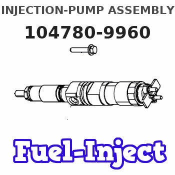
Information injection-pump assembly
BOSCH
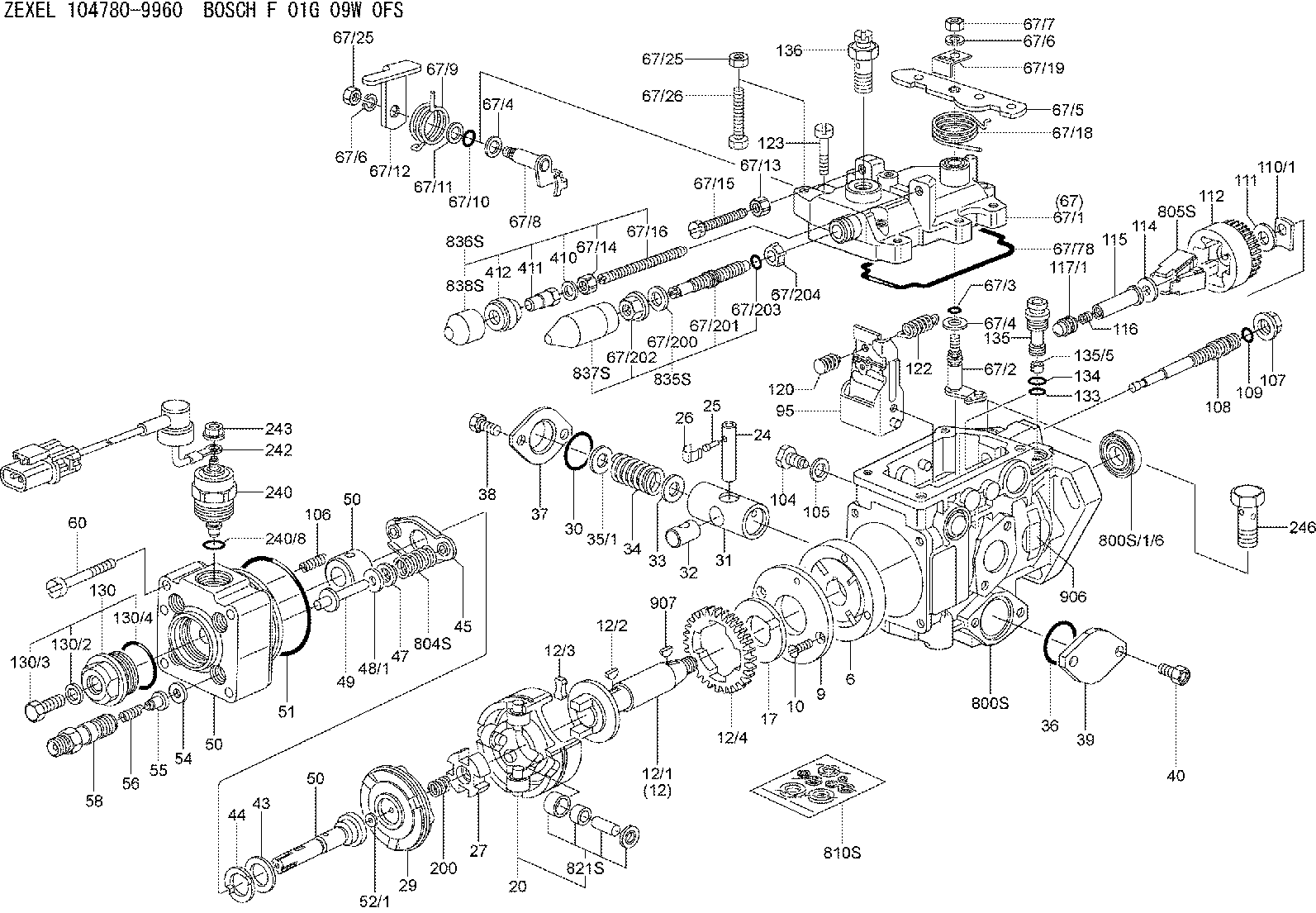
F 01G 09W 0FS
f01g09w0fs
ZEXEL
104780-9960
1047809960
NISSAN-DIESEL
16700NA01A
16700na01a
Rating:
Compare Prices: .
As an associate, we earn commssions on qualifying purchases through the links below

Diesel VE Fuel Injection Pump, Compatible With NISSAN TD27 Engine Replacement Parts 104680-9960 104780-9960 NP-VE4/10F1050RNP2614 16700NA01A
CHENUXO Diesel VE Fuel Injection Pump , Compatible With NISSAN TD27 Engine Replacement Parts 104680-9960 104780-9960 NP-VE4/10F1050RNP2614 16700NA01A || Efficient and energy-saving: It can meet the fuel demand of the engine while reducing energy consumption, which helps to improve fuel economy. || High reliability: Adopting advanced manufacturing processes to effectively reduce wear and tear. Ensure stable operation in various harsh environments. || Optimization design: The installation site adopts soundproof and shock-absorbing materials, further reducing the propagation of noise. || Monitoring feedback: Real time monitoring of fuel pressure, temperature, liquid level and other parameters, and feedback to the ECU.
CHENUXO Diesel VE Fuel Injection Pump , Compatible With NISSAN TD27 Engine Replacement Parts 104680-9960 104780-9960 NP-VE4/10F1050RNP2614 16700NA01A || Efficient and energy-saving: It can meet the fuel demand of the engine while reducing energy consumption, which helps to improve fuel economy. || High reliability: Adopting advanced manufacturing processes to effectively reduce wear and tear. Ensure stable operation in various harsh environments. || Optimization design: The installation site adopts soundproof and shock-absorbing materials, further reducing the propagation of noise. || Monitoring feedback: Real time monitoring of fuel pressure, temperature, liquid level and other parameters, and feedback to the ECU.

Fuel Pump 104780-9960 1047809960 Compatible For NISSAN TD27 New Engine Replacement Parts Fuel Supply System Fuel Pumps
YPMOICBH The fuel pump allows the fuel tank to be placed away from the engine, making it easier for car design layout || When the engine stops, the control module turns off the power to the fuel pump to prevent accidental ignition || The fuel pump extracts fuel from the fuel tank and delivers it to the engine through the fuel supply pipeline, ensuring a continuous and stable fuel supply during engine operation || The fuel pump cooperates with the fuel pressure regulator to establish an appropriate fuel pressure, ensuring that the fuel can flow smoothly to the engine and meet the requirements of the injection system || Fuel Pump 104780-9960 1047809960 Compatible For NISSAN TD27 New Engine Replacement Parts Fuel Supply System Fuel Pumps
YPMOICBH The fuel pump allows the fuel tank to be placed away from the engine, making it easier for car design layout || When the engine stops, the control module turns off the power to the fuel pump to prevent accidental ignition || The fuel pump extracts fuel from the fuel tank and delivers it to the engine through the fuel supply pipeline, ensuring a continuous and stable fuel supply during engine operation || The fuel pump cooperates with the fuel pressure regulator to establish an appropriate fuel pressure, ensuring that the fuel can flow smoothly to the engine and meet the requirements of the injection system || Fuel Pump 104780-9960 1047809960 Compatible For NISSAN TD27 New Engine Replacement Parts Fuel Supply System Fuel Pumps

VE4 Fuel Injection Pump for Nissan TD27 Engine 104780-9960 16700-NA01A
KoovDem Part Number: 104780-9960, 1047809960, 16700-NA01A, 16700NA01A, VE4/10F1050RNP2614 || Compatible Model: for Nissan TD27 Engine || Effective and Reliable: Utilizing cutting-edge technology, this system delivers effective and reliable fuel supply, guaranteeing smooth vehicle performance. || Rugged and Dependable: With a track record of being rigorously tested and proven, this product offers durability and reliability, ensuring it operates consistently even in the harshest of environments. || Straightforward Installation: With a user-friendly interface, installing this product is a breeze. Simply plug it in and you're good to go, no technical expertise needed.
KoovDem Part Number: 104780-9960, 1047809960, 16700-NA01A, 16700NA01A, VE4/10F1050RNP2614 || Compatible Model: for Nissan TD27 Engine || Effective and Reliable: Utilizing cutting-edge technology, this system delivers effective and reliable fuel supply, guaranteeing smooth vehicle performance. || Rugged and Dependable: With a track record of being rigorously tested and proven, this product offers durability and reliability, ensuring it operates consistently even in the harshest of environments. || Straightforward Installation: With a user-friendly interface, installing this product is a breeze. Simply plug it in and you're good to go, no technical expertise needed.
You can express buy:
USD 479.3
14-06-2025
14-06-2025
Diesel injector Fuel Pump 104680-9960 NP-VE4/10F1050RNP2614 16700NA01A For NISSAN TD27
USD 418.2
17-05-2025
17-05-2025
Diesel Fuel Injection Pump 104780-9960 NP-VE4/10F1050RNP2614 16700NA01A For NISSAN
Images:
USD 892.23

[13-May-2025]
USD 409.13

[03-May-2025]
USD 433.07

[19-May-2025]
Components :
| 0. | INJECTION-PUMP ASSEMBLY | 104780-9960 |
| 1. | _ | |
| 2. | FUEL INJECTION PUMP | |
| 3. | NUMBER PLATE | |
| 4. | _ | |
| 5. | CAPSULE | |
| 6. | ADJUSTING DEVICE | |
| 7. | NOZZLE AND HOLDER ASSY | 105148-1121 |
| 8. | Nozzle and Holder | |
| 9. | Open Pre:MPa(Kqf/cm2) | 9.8(100) |
| 10. | NOZZLE-HOLDER | 105078-0050 |
| 11. | NOZZLE | 105007-1130 |
Scheme ###:
| 1/6. | [1] | 146601-0900 | PACKING RING |
| 6. | [1] | 146100-0020 | SUPPLY PUMP |
| 9. | [1] | 146103-0000 | COVER |
| 10. | [2] | 139104-0000 | FLAT-HEAD SCREW |
| 12. | [1] | 146200-0020 | DRIVE SHAFT |
| 12/1. | [1] | 146200-0000 | DRIVE SHAFT |
| 12/2. | [1] | 146201-0000 | WOODRUFF KEY |
| 12/3. | [2] | 146202-0100 | DAMPER |
| 12/4. | [1] | 146203-0000 | TOOTHED GEAR |
| 17. | [1] | 146204-0000 | PLAIN WASHER |
| 20. | [1] | 146210-1720 | ROLLER SET |
| 24. | [1] | 146303-0100 | BEARING PIN |
| 25. | [1] | 146304-0000 | BEARING PIN |
| 26. | [1] | 146305-0000 | CLAMPING BAND |
| 27. | [1] | 146205-0000 | SLOTTED WASHER |
| 29. | [1] | 146220-5920 | CAM PLATE |
| 30. | [1] | 146600-0800 | O-RING |
| 31. | [1] | 146300-0000 | PUMP PLUNGER |
| 32. | [1] | 146301-0000 | SLIDING PIECE |
| 33. | [1] | 146603-0700 | SHIM |
| 34. | [1] | 146302-3500 | COMPRESSION SPRING |
| 34B. | [1] | 146302-3400 | COMPRESSION SPRING |
| 34C. | [1] | 146302-3600 | COMPRESSION SPRING |
| 35/1. | [0] | 146603-0700 | SHIM D17.5&7.5T0.60 |
| 35/1. | [0] | 146603-0800 | SHIM D17.5&7.5T0.70 |
| 35/1. | [0] | 146603-0900 | SHIM D17.5&7.5T0.90 |
| 35/1. | [0] | 146603-1000 | SHIM D17.5&7.5T1.00 |
| 35/1. | [0] | 146603-1100 | SHIM D17.5&7.5T1.20 |
| 35/1. | [0] | 146603-3600 | SHIM D17.5&7.5T2.40 |
| 36. | [1] | 146600-0800 | O-RING |
| 37. | [1] | 146310-0700 | COVER |
| 38. | [2] | 146620-5000 | BLEEDER SCREW |
| 39. | [1] | 146310-0100 | COVER |
| 40. | [2] | 146620-5000 | BLEEDER SCREW |
| 43. | [1] | 146230-0000 | SHIM |
| 44. | [1] | 146230-0100 | PLAIN WASHER |
| 45. | [1] | 146231-0001 | SLOTTED WASHER |
| 47. | [2] | 146233-0000 | SLOTTED WASHER |
| 48/1. | [1] | 146603-0100 | SHIM D17.0&5.2T0.80 |
| 48/1. | [1] | 146603-0200 | SHIM D17.0&5.2T1.00 |
| 48/1. | [1] | 146603-0300 | SHIM D17.0&5.2T1.20 |
| 48/1. | [1] | 146603-0400 | SHIM D17.0&5.2T1.50 |
| 48/1. | [1] | 146690-1400 | SHIM D17&5.2T0.9 |
| 48/1. | [1] | 146690-1500 | SHIM D17&5.2T1.1 |
| 48/1. | [1] | 146690-1600 | SHIM D17&5.2T1.3 |
| 48/1. | [1] | 146690-1700 | SHIM D17&5.2T1.4 |
| 48/1. | [1] | 146690-1800 | SHIM D17&5.2T1.6 |
| 49. | [2] | 146234-0500 | GUIDE PIN |
| 50. | [1] | 146401-0520 | HYDRAULIC HEAD |
| 50. | [1] | 146401-0520 | HYDRAULIC HEAD |
| 50. | [1] | 146401-0520 | HYDRAULIC HEAD |
| 51. | [1] | 146600-0000 | O-RING |
| 52/1. | [1] | 146420-0200 | SHIM D9.5&3.0T1.94 |
| 52/1. | [1] | 146420-0700 | SHIM D9.5&3.0T2.04 |
| 52/1. | [1] | 146420-1200 | SHIM D9.5&3.0T2.14 |
| 52/1. | [1] | 146420-1700 | SHIM D9.5&3.0T2.24 |
| 52/1. | [1] | 146420-2200 | SHIM D9.5&3.0T2.34 |
| 52/1. | [1] | 146420-2700 | SHIM D9.5&3.0T2.44 |
| 52/1. | [1] | 146420-3200 | SHIM D9.5&3.0T2.54 |
| 52/1. | [1] | 146420-3700 | SHIM D9.5&3.0T2.64 |
| 52/1. | [1] | 146420-5600 | SHIM D9.5&3.0T1.84 |
| 54. | [4] | 146433-0100 | GASKET |
| 55. | [4] | 146430-0320 | DELIVERY-VALVE ASSEMBLY VE4 |
| 56. | [4] | 146432-0000 | COMPRESSION SPRING |
| 58. | [4] | 146440-0220 | FITTING |
| 60. | [4] | 139106-0100 | FLAT-HEAD SCREW |
| 67. | [1] | 146822-3120 | GOVERNOR COVER |
| 67/1. | [1] | 146805-2120 | GOVERNOR COVER |
| 67/2. | [1] | 146515-0320 | CONTROL SHAFT |
| 67/3. | [1] | 146600-0100 | O-RING |
| 67/4. | [2] | 139310-0200 | PLAIN WASHER |
| 67/4. | [2] | 139310-0200 | PLAIN WASHER |
| 67/5. | [1] | 146530-0000 | CONTROL LEVER |
| 67/5B. | [1] | 146530-0100 | CONTROL LEVER STAMP 001 |
| 67/5C. | [1] | 146832-1500 | CONTROL LEVER |
| 67/5D. | [1] | 146832-1600 | CONTROL LEVER |
| 67/6. | [2] | 014110-6440 | LOCKING WASHER D12.2&6.1T1.5 |
| 67/6. | [2] | 014110-6440 | LOCKING WASHER D12.2&6.1T1.5 |
| 67/7. | [1] | 013020-6040 | UNION NUT |
| 67/8. | [1] | 146515-1820 | LEVER SHAFT |
| 67/9. | [1] | 146592-0400 | COILED SPRING |
| 67/10. | [1] | 146600-0200 | O-RING |
| 67/11. | [1] | 146602-0100 | PLAIN WASHER |
| 67/12. | [1] | 146540-4000 | CONTROL LEVER |
| 67/12B. | [1] | 146540-4100 | CONTROL LEVER |
| 67/13. | [1] | 146621-1700 | UNION NUT |
| 67/14. | [1] | 146621-1700 | UNION NUT |
| 67/15. | [1] | 146526-3400 | BLEEDER SCREW |
| 67/16. | [1] | 146526-6900 | FLAT-HEAD SCREW |
| 67/18. | [1] | 146594-0600 | COILED SPRING |
| 67/19. | [1] | 146541-0000 | ANGLE PIECE |
| 67/25. | [2] | 013020-6040 | UNION NUT |
| 67/25. | [2] | 013020-6040 | UNION NUT |
| 67/26. | [1] | 139006-0200 | BLEEDER SCREW |
| 67/78. | [1] | 146600-4400 | SEAL RING |
| 67/200. | [1] | 139308-0300 | PLAIN WASHER |
| 67/201. | [1] | 146545-4600 | THREADED PIN L=24MM |
| 67/201B. | [1] | 146545-4700 | THREADED PIN L=26MM |
| 67/201C. | [1] | 146545-4800 | THREADED PIN L=28MM |
| 67/202. | [1] | 146598-5000 | UNION NUT |
| 67/203. | [1] | 146600-1200 | O-RING |
| 67/204. | [1] | 146545-4500 | DAMPER |
| 95. | [1] | 146861-0120 | FULCRUM LEVER |
| 104. | [2] | 146568-0000 | SLOTTED SPRING PIN |
| 105. | [2] | 026508-1140 | GASKET D11.4&8.2T1.0 |
| 106. | [2] | 146588-0500 | COILED SPRING |
| 107. | [1] | 146569-0300 | UNION NUT |
| 108. | [1] | 146570-0100 | GOVERNOR SHAFT |
| 109. | [1] | 146600-0400 | O-RING |
| 110/1. | [1] | 146571-0000 | SHIM D20.2&8.3T1.05 |
| 110/1. | [1] | 146571-0100 | SHIM D20.2&8.3T1.25 |
| 110/1. | [1] | 146571-0200 | SHIM D20.2&8.3T1.45 |
| 110/1. | [1] | 146571-0300 | SHIM D20.2&8.3T1.65 |
| 110/1. | [1] | 146571-0400 | SHIM D20.2&8.3T1.85 |
| 111. | [1] | 146602-0600 | PLAIN WASHER |
| 112. | [1] | 146572-0020 | FLYWEIGHT ASSEMBLY |
| 114. | [1] | 146602-2600 | PLAIN WASHER |
| 115. | [1] | 146976-3800 | SLIDING SLEEVE |
| 116. | [1] | 146576-0400 | CAP |
| 117/1. | [1] | 146877-1020 | PLUG L=5.2 |
| 117/1. | [1] | 146877-1120 | PLUG L=5.3 |
| 117/1. | [1] | 146877-1220 | PLUG L=5.4 |
| 117/1. | [1] | 146877-1320 | PLUG L=5.5 |
| 117/1. | [1] | 146877-1420 | PLUG L=5.6 |
| 117/1. | [1] | 146877-1520 | PLUG L=5.7 |
| 117/1. | [1] | 146877-1620 | PLUG L=5.8 |
| 117/1. | [1] | 146877-1720 | PLUG L=5.9 |
| 117/1. | [1] | 146877-1820 | PLUG L=6.0 |
| 117/1. | [1] | 146877-1920 | PLUG L=6.1 |
| 117/1. | [1] | 146877-2020 | PLUG L=6.2 |
| 117/1. | [1] | 146877-2120 | PLUG L=6.3 |
| 117/1. | [1] | 146877-2220 | PLUG L=6.4 |
| 117/1. | [1] | 146877-2320 | PLUG L=6.5 |
| 117/1. | [1] | 146877-2420 | PLUG L=6.6 |
| 117/1. | [1] | 146877-2520 | PLUG L=6.7 |
| 117/1. | [1] | 146877-2620 | PLUG L=6.8 |
| 120. | [1] | 146879-6920 | RETAINING PIN |
| 122. | [1] | 146580-3900 | GOVERNOR SPRING |
| 123. | [4] | 139106-0200 | FLAT-HEAD SCREW |
| 130. | [1] | 146421-0020 | CAPSULE |
| 130/2. | [1] | 026508-1140 | GASKET D11.4&8.2T1.0 |
| 130/3. | [1] | 146422-0000 | BLEEDER SCREW |
| 130/4. | [1] | 146600-0500 | O-RING |
| 133. | [1] | 146600-0600 | O-RING |
| 134. | [1] | 146600-0700 | O-RING |
| 135. | [1] | 146110-0220 | CONTROL VALVE STAMP 02 |
| 135/5. | [1] | 146114-0000 | SPRING WASHER |
| 136. | [1] | 146120-0120 | OVER FLOW VALVE |
| 200. | [1] | 146206-0100 | COILED SPRING |
| 240. | [1] | 146650-0720 | PULLING ELECTROMAGNET |
| 240/8. | [1] | 146600-1700 | O-RING |
| 242. | [1] | 146662-8320 | WIRE |
| 243. | [1] | 146621-4901 | UNION NUT |
| 246. | [1] | 027412-2440 | EYE BOLT |
| 410. | [1] | 014020-6140 | PLAIN WASHER D11.5&6.5 |
| 411. | [1] | 146598-6300 | CAP NUT |
| 412. | [1] | 146598-6400 | ADAPTOR |
| 800S. | [1] | 146009-9220 | PUMP HOUSING |
| 800S/1/6. | [1] | 146601-0900 | PACKING RING |
| 804S. | [1] | 146232-0320 | COMPRESSION SPRING |
| 805S. | [1] | 146574-0320 | PARTS SET |
| 810S. | [1] | 146600-1120 | REPAIR SET |
| 821S. | [1] | 146210-5720 | ROLLER SET |
| 835S. | [1] | 146598-7320 | CAP |
| 836S. | [1] | 146598-7420 | CAP |
| 837S. | [1] | 146598-7310 | CAP |
| 838S. | [1] | 146598-6710 | CAP |
| 906. | [1] | 146984-8400 | NAMEPLATE |
| 907. | [1] | 025803-1640 | WOODRUFF KEY |
Include in #2:
104780-9960
as INJECTION-PUMP ASSEMBLY
Cross reference number
BOSCH
F 01G 09W 0FS
f01g09w0fs
ZEXEL
104780-9960
1047809960
NISSAN-DIESEL
16700NA01A
16700na01a
Zexel num
Bosch num
Firm num
Name
104780-9960
F 01G 09W 0FS
16700NA01A NISSAN-DIESEL
INJECTION-PUMP ASSEMBLY
TD27 K
TD27 K
Calibration Data:
Adjustment conditions
Test oil
1404 Test oil ISO4113orSAEJ967d
1404 Test oil ISO4113orSAEJ967d
Test oil temperature
degC
45
45
50
Nozzle
105780-0060
Bosch type code
NP-DN0SD1510
Nozzle holder
105780-2150
Opening pressure
MPa
13
13
13.3
Opening pressure
kgf/cm2
133
133
136
Injection pipe
157805-7320
Injection pipe
Inside diameter - outside diameter - length (mm) mm 2-6-450
Inside diameter - outside diameter - length (mm) mm 2-6-450
Joint assembly
157641-4720
Tube assembly
157641-4020
Transfer pump pressure
kPa
20
20
20
Transfer pump pressure
kgf/cm2
0.2
0.2
0.2
Direction of rotation (viewed from drive side)
Right R
Right R
Injection timing adjustment
Pump speed
r/min
900
900
900
Average injection quantity
mm3/st.
47.4
46.9
47.9
Difference in delivery
mm3/st.
3
Basic
*
Oil temperature
degC
50
48
52
Injection timing adjustment_02
Pump speed
r/min
500
500
500
Average injection quantity
mm3/st.
45.2
42.7
47.7
Oil temperature
degC
48
46
50
Injection timing adjustment_03
Pump speed
r/min
700
700
700
Average injection quantity
mm3/st.
48.1
48.1
48.1
Oil temperature
degC
50
48
52
Injection timing adjustment_04
Pump speed
r/min
900
900
900
Average injection quantity
mm3/st.
47.4
46.4
48.4
Difference in delivery
mm3/st.
3.5
Basic
*
Oil temperature
degC
50
48
52
Injection timing adjustment_05
Pump speed
r/min
1050
1050
1050
Average injection quantity
mm3/st.
47.9
44.4
51.4
Oil temperature
degC
50
48
52
Injection quantity adjustment
Pump speed
r/min
1200
1200
1200
Average injection quantity
mm3/st.
33.1
30.1
36.1
Basic
*
Oil temperature
degC
50
48
52
Injection quantity adjustment_02
Pump speed
r/min
1400
1400
1400
Average injection quantity
mm3/st.
5
Oil temperature
degC
50
48
52
Injection quantity adjustment_03
Pump speed
r/min
1200
1200
1200
Average injection quantity
mm3/st.
33.1
29.6
36.6
Basic
*
Oil temperature
degC
50
48
52
Injection quantity adjustment_04
Pump speed
r/min
1285
1285
1285
Average injection quantity
mm3/st.
15.2
15.2
15.2
Oil temperature
degC
50
48
52
Governor adjustment
Pump speed
r/min
650
650
650
Average injection quantity
mm3/st.
8.3
6.3
10.3
Difference in delivery
mm3/st.
2
Basic
*
Oil temperature
degC
50
48
52
Governor adjustment_02
Pump speed
r/min
650
650
650
Average injection quantity
mm3/st.
8.3
5.8
10.8
Difference in delivery
mm3/st.
2.5
Basic
*
Oil temperature
degC
50
48
52
Timer adjustment
Pump speed
r/min
100
100
100
Average injection quantity
mm3/st.
55
50
60
Basic
*
Oil temperature
degC
48
46
50
Remarks
Full
Full
Timer adjustment_02
Pump speed
r/min
100
100
100
Average injection quantity
mm3/st.
55
50
60
Oil temperature
degC
48
46
50
Remarks
Full
Full
Speed control lever angle
Pump speed
r/min
650
650
650
Average injection quantity
mm3/st.
0
0
0
Oil temperature
degC
50
48
52
Remarks
Magnet OFF at idling position
Magnet OFF at idling position
0000000901
Pump speed
r/min
900
900
900
Overflow quantity
cm3/min
410
280
540
Oil temperature
degC
50
48
52
Stop lever angle
Pump speed
r/min
900
900
900
Pressure
kPa
392
363
421
Pressure
kgf/cm2
4
3.7
4.3
Basic
*
Oil temperature
degC
50
48
52
Stop lever angle_02
Pump speed
r/min
700
700
700
Pressure
kPa
343
304
382
Pressure
kgf/cm2
3.5
3.1
3.9
Oil temperature
degC
50
48
52
Stop lever angle_03
Pump speed
r/min
900
900
900
Pressure
kPa
392
353
431
Pressure
kgf/cm2
4
3.6
4.4
Basic
*
Oil temperature
degC
50
48
52
0000001101
Pump speed
r/min
900
900
900
Timer stroke
mm
2
1.8
2.2
Basic
*
Oil temperature
degC
50
48
52
_02
Pump speed
r/min
700
700
700
Timer stroke
mm
1.2
0.6
1.8
Oil temperature
degC
50
48
52
_03
Pump speed
r/min
900
900
900
Timer stroke
mm
2
1.6
2.4
Basic
*
Oil temperature
degC
50
48
52
_04
Pump speed
r/min
1250
1250
1250
Timer stroke
mm
3.3
2.8
3.7
Oil temperature
degC
50
48
52
0000001201
Max. applied voltage
V
8
8
8
Test voltage
V
13
12
14
Timing setting
K dimension
mm
3.3
3.2
3.4
KF dimension
mm
5.8
5.7
5.9
MS dimension
mm
1.8
1.7
1.9
Control lever angle alpha
deg.
14
10
18
Control lever angle beta
deg.
23
18
28
Test data Ex:
0000001801 STOP LEVER ADJUSTMENT
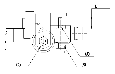
Adjustment of the stop lever
Adjust adjusting bolt (B) so that the starting injection quantity is within the standard.
Fix using nut.
(A) Adjusting nut
(C) Starting injection quantity adjusting lever
----------
----------
L=15.0~18.5mm
----------
----------
L=15.0~18.5mm
0000001901 TAMPER PROOF
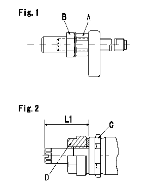
Tamperproof installation procedure
A:Nut
B:Nut
C:Rubber vibration damper
D:Nut
L1:Inspection dimension
Fig. 1 Maximum speed adjusting screw
1) Tighten nut (A) to the torque T1.
2) To prevent nut (A) from turning together, fix (A) using the tool, then tighten nut (B) to torque T1
Fig.2 Full load adjusting screw
1) Confirm the position of the rubber vibration damper (C) and then tighten nut (D) to the torque T2.
----------
L1=23~28mm T1=6~9N-m(0.6~0.9kgf-m) T2=7~9N-m(0.7~0.9kgf-m)
----------
L1=23~28mm
----------
L1=23~28mm T1=6~9N-m(0.6~0.9kgf-m) T2=7~9N-m(0.7~0.9kgf-m)
----------
L1=23~28mm
Information:
Do not use the same vacuum sampling pump for extracting oil samples that is used for extracting coolant samples.A small residue of either type sample may remain in the pump and may cause a false positive analysis for the sample being taken.Always use a separate pump for oil sampling and a separate pump for coolant sampling.Failure to do so may cause a false analysis which could lead to customer and dealer concerns.
New Systems, Refilled Systems, and Converted Systems
Perform an S O S coolant analysis (Level 2) at the following maintenance intervals.
Initial 500 service hours
Every Year or every 2000 hours, whichever comes firstPerform this analysis at the interval that occurs first for new systems, for refilled systems, or for converted systems that use Cat ELC (Extended Life Coolant) or use Cat DEAC (Diesel Engine Antifreeze/Coolant). This 500 hour check will also check for any residual cleaner that may have contaminated the system.Recommended Interval for S O S Services Coolant Sample
The following table contains the recommended sampling interval for all coolants that meet Cat EC-1 (Engine Coolant specification - 1). This is also the recommended sampling interval for all conventional heavy-duty coolant/antifreeze.The Level 2 Coolant Analysis should be performed if a problem is suspected or identified.
Table 1
Recommended Interval
Type of Coolant Level 1 Level 2
Cat DEAC
and Conventional Heavy-Duty Coolants Every 250 hours Yearly
Cat ELC
and Commercial EC-1 coolants Optional or every 500 hours Yearly or every 500 hours Note: Check the SCA (Supplemental Coolant Additive) of the conventional coolant at every oil change or at every 250 hours. Perform this check at the interval that occurs first.Refer to your machine OMM for recommendations specific to your machine.S O S Services Coolant Analysis (Level 1)
A coolant analysis (Level 1) is a test of the properties of the coolant.The following properties of the coolant are tested:
Glycol concentration for freeze protection and boil protection
Ability to protect from erosion and corrosion
pH
Conductivity
Visual analysis
Odor analysisThe results are reported, and appropriate recommendations are made.S O S Services Coolant Analysis (Level 2)
A coolant analysis ( Level 2) is a comprehensive chemical evaluation of the coolant. This analysis is also a check of the overall condition of the cooling system.The S O S coolant analysis ( Level 2) has the following features:
Full coolant analysis (Level 1)
Identification of metal corrosion and of contaminants
Identification of buildup of the impurities that cause corrosion
Identification of buildup of the impurities that cause scaling
Determination of the possibility of electrolysis within the cooling system of the engineThe results are reported, and appropriate recommendations are made.For more information on S O S coolant analysis, consult your Caterpillar dealer.
Have questions with 104780-9960?
Group cross 104780-9960 ZEXEL
Nissan-Diesel
104780-9960
F 01G 09W 0FS
16700NA01A
INJECTION-PUMP ASSEMBLY
TD27
TD27