Information injection-pump assembly
BOSCH
9 460 614 798
9460614798
ZEXEL
104780-9780
1047809780
NISSAN-DIESEL
1670058G11
1670058g11
Rating:
Cross reference number
BOSCH
9 460 614 798
9460614798
ZEXEL
104780-9780
1047809780
NISSAN-DIESEL
1670058G11
1670058g11
Zexel num
Bosch num
Firm num
Name
104780-9780
9 460 614 798
1670058G11 NISSAN-DIESEL
INJECTION-PUMP ASSEMBLY
TD27 K
TD27 K
Calibration Data:
Adjustment conditions
Test oil
1404 Test oil ISO4113orSAEJ967d
1404 Test oil ISO4113orSAEJ967d
Test oil temperature
degC
45
45
50
Nozzle
105780-0060
Bosch type code
NP-DN0SD1510
Nozzle holder
105780-2150
Opening pressure
MPa
13
13
13.3
Opening pressure
kgf/cm2
133
133
136
Injection pipe
157805-7320
Injection pipe
Inside diameter - outside diameter - length (mm) mm 2-6-450
Inside diameter - outside diameter - length (mm) mm 2-6-450
Joint assembly
157641-4720
Tube assembly
157641-4020
Transfer pump pressure
kPa
20
20
20
Transfer pump pressure
kgf/cm2
0.2
0.2
0.2
Direction of rotation (viewed from drive side)
Right R
Right R
Injection timing adjustment
Pump speed
r/min
1100
1100
1100
Average injection quantity
mm3/st.
50
49.5
50.5
Difference in delivery
mm3/st.
3
Basic
*
Oil temperature
degC
50
48
52
Injection timing adjustment_02
Pump speed
r/min
600
600
600
Average injection quantity
mm3/st.
51.4
48.4
54.4
Oil temperature
degC
50
48
52
Injection timing adjustment_03
Pump speed
r/min
1100
1100
1100
Average injection quantity
mm3/st.
50
49
51
Difference in delivery
mm3/st.
3.5
Basic
*
Oil temperature
degC
50
48
52
Injection timing adjustment_04
Pump speed
r/min
2150
2150
2150
Average injection quantity
mm3/st.
46.2
43.2
49.2
Oil temperature
degC
52
50
54
Injection quantity adjustment
Pump speed
r/min
2350
2350
2350
Average injection quantity
mm3/st.
41
39
43
Basic
*
Oil temperature
degC
52
50
54
Injection quantity adjustment_02
Pump speed
r/min
2700
2700
2700
Average injection quantity
mm3/st.
5
Oil temperature
degC
55
52
58
Injection quantity adjustment_03
Pump speed
r/min
2350
2350
2350
Average injection quantity
mm3/st.
41
38
44
Basic
*
Oil temperature
degC
52
50
54
Injection quantity adjustment_04
Pump speed
r/min
2550
2550
2550
Average injection quantity
mm3/st.
13.5
9
18
Oil temperature
degC
55
52
58
Governor adjustment
Pump speed
r/min
350
350
350
Average injection quantity
mm3/st.
8.4
6.4
10.4
Difference in delivery
mm3/st.
2
Basic
*
Oil temperature
degC
48
46
50
Governor adjustment_02
Pump speed
r/min
350
350
350
Average injection quantity
mm3/st.
8.4
5.9
10.9
Difference in delivery
mm3/st.
2.5
Basic
*
Oil temperature
degC
48
46
50
Timer adjustment
Pump speed
r/min
300
300
300
Average injection quantity
mm3/st.
52.5
50.5
54.5
Basic
*
Oil temperature
degC
48
46
50
Remarks
Full
Full
Timer adjustment_02
Pump speed
r/min
300
300
300
Average injection quantity
mm3/st.
52.5
50
55
Basic
*
Oil temperature
degC
48
46
50
Remarks
Full
Full
Speed control lever angle
Pump speed
r/min
350
350
350
Average injection quantity
mm3/st.
0
0
0
Oil temperature
degC
48
46
50
Remarks
Magnet OFF at idling position
Magnet OFF at idling position
0000000901
Pump speed
r/min
1100
1100
1100
Overflow quantity
cm3/min
390
260
520
Oil temperature
degC
50
48
52
Stop lever angle
Pump speed
r/min
1100
1100
1100
Pressure
kPa
432
403
461
Pressure
kgf/cm2
4.4
4.1
4.7
Basic
*
Oil temperature
degC
50
48
52
Stop lever angle_02
Pump speed
r/min
1100
1100
1100
Pressure
kPa
432
393
471
Pressure
kgf/cm2
4.4
4
4.8
Basic
*
Oil temperature
degC
50
48
52
Stop lever angle_03
Pump speed
r/min
1700
1700
1700
Pressure
kPa
579
540
618
Pressure
kgf/cm2
5.9
5.5
6.3
Oil temperature
degC
50
48
52
0000001101
Pump speed
r/min
1100
1100
1100
Timer stroke
mm
2.6
2.4
2.8
Basic
*
Oil temperature
degC
50
48
52
_02
Pump speed
r/min
700
700
700
Timer stroke
mm
0.5
0.5
Oil temperature
degC
50
48
52
_03
Pump speed
r/min
1100
1100
1100
Timer stroke
mm
2.5
2.3
2.9
Basic
*
Oil temperature
degC
50
48
52
_04
Pump speed
r/min
1700
1700
1700
Timer stroke
mm
4.6
4.4
5.4
Oil temperature
degC
50
48
52
_05
Pump speed
r/min
2550
2550
2550
Timer stroke
mm
7.4
6.9
7.8
Oil temperature
degC
55
52
58
0000001201
Max. applied voltage
V
8
8
8
Test voltage
V
13
12
14
Timing setting
K dimension
mm
3.3
3.2
3.4
KF dimension
mm
5.8
5.7
5.9
MS dimension
mm
0.9
0.8
1
Control lever angle alpha
deg.
55.5
51.5
59.5
Control lever angle beta
deg.
36
31
41
Test data Ex:
0000001801 STOP LEVER ADJUSTMENT
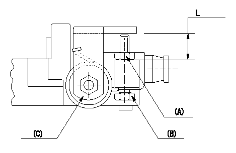
Adjustment of the stop lever
Adjust adjusting bolt (B) so that the starting injection quantity is within the standard.
Fix using nut.
(A) Adjusting nut
(C) Starting injection quantity adjusting lever
----------
----------
L=15.0~18.5mm
----------
----------
L=15.0~18.5mm
Information:
Use the following tests for troubleshooting and repair steps. Use the ""Test for Cylinder Cutout"" in order to determine if the replacement of individual injectors is needed. Replace suspect injectors with the part number of the original injector. Use the ""Test for Leakage from Poppet Valve"" in order to determine if the full set of injectors need to be replaced. For replacement of the full set of injectors, use the current injectors and new software that is listed in Table 2.Test for Cylinder Cutout
The cylinder cutout test should be used in order to determine if an individual injector may have caused the failure.
Warm the engine out of cold mode.
Connect Cat ET to the engine while the engine is running.
Ensure that the engine speed is 1200 rpm 125 rpm. An extremely rough running engine will need to be diagnosed by other methods.
Cut out one bank of cylinders. Note engine rpm and the fuel position on the Cat ET screen at that time.
Cut out one of the remaining cylinders from the cylinder bank that is running. Allow the engine to stabilize, and note the fuel position.
Give power back to that cylinder. Allow the engine to stabilize. Note the fuel position.
Repeat steps 5 through 6 until the cylinder bank has been completely checked.
Power all cylinders. Allow the engine to stabilize.
Cut out the other cylinder bank and repeat steps 5 through 8.
Repeat steps 4 through 9 with the engine at 2000 rpm.
Compare the results from the fuel position from each cylinder.
If the cylinder was cut out and the fuel position did not change the cylinder may not have been producing power. This cylinder would be suspect.
When you are finished with the test, reduce engine RPM to low idle. Shut off the engine.
Replace any suspect injector with a similar original injector. Install new seals for the injector and the jumper tube during this repair. The repair procedure for the injector is found in Special Instruction, REHS0116.It is possible that multiple injectors are functioning improperly. Complete ""Test for Leakage from Poppet Valve"" in order to evaluate possible excessive leakage from the injectors.Test for Leakage from Poppet Valve
Warm the engine out of Cold Mode to normal operating temperature.
Turn off the engine.
Remove the valve cover bolts in preparation in order to observe the injectors. Leave the covers in place.
Hot oil and components can cause personal injury.Do not allow hot oil or components to contact skin.
Restart the engine and run at low idle with no load.
Use Cat ET in order to perform the test that overrides the injection actuation system. Increase injection actuation pressure to the maximum value.
Observe all of the injectors under each valve cover for leakage at the spill port. A small amount of dripping is acceptable. However, a continuous stream of oil is an indication of excessive leakage of the poppet valve. Only leaks at the spill port are an indication of excessive leakage from the poppet valve.
If multiple injectors display excessive leakage from the poppet valves, update the set of injectors with
Have questions with 104780-9780?
Group cross 104780-9780 ZEXEL
Nissan-Diesel
104780-9780
9 460 614 798
1670058G11
INJECTION-PUMP ASSEMBLY
TD27
TD27