Information injection-pump assembly
BOSCH
9 460 614 795
9460614795
ZEXEL
104780-9720
1047809720
NISSAN-DIESEL
167002S519
167002s519
Rating:
Cross reference number
BOSCH
9 460 614 795
9460614795
ZEXEL
104780-9720
1047809720
NISSAN-DIESEL
167002S519
167002s519
Zexel num
Bosch num
Firm num
Name
104780-9720
9 460 614 795
167002S519 NISSAN-DIESEL
INJECTION-PUMP ASSEMBLY
TD27 K
TD27 K
Calibration Data:
Adjustment conditions
Test oil
1404 Test oil ISO4113orSAEJ967d
1404 Test oil ISO4113orSAEJ967d
Test oil temperature
degC
45
45
50
Nozzle
105780-0060
Bosch type code
NP-DN0SD1510
Nozzle holder
105780-2150
Opening pressure
MPa
13
13
13.3
Opening pressure
kgf/cm2
133
133
136
Injection pipe
157805-7320
Injection pipe
Inside diameter - outside diameter - length (mm) mm 2-6-450
Inside diameter - outside diameter - length (mm) mm 2-6-450
Joint assembly
157641-4720
Tube assembly
157641-4020
Transfer pump pressure
kPa
20
20
20
Transfer pump pressure
kgf/cm2
0.2
0.2
0.2
Direction of rotation (viewed from drive side)
Right R
Right R
Injection timing adjustment
Pump speed
r/min
1100
1100
1100
Average injection quantity
mm3/st.
44.6
44.1
45.1
Difference in delivery
mm3/st.
3.5
Basic
*
Oil temperature
degC
50
48
52
Injection timing adjustment_02
Pump speed
r/min
500
500
500
Average injection quantity
mm3/st.
40.3
37.3
43.3
Oil temperature
degC
48
46
50
Injection timing adjustment_03
Pump speed
r/min
850
850
850
Average injection quantity
mm3/st.
42
39.5
44.5
Oil temperature
degC
50
48
52
Injection timing adjustment_04
Pump speed
r/min
1100
1100
1100
Average injection quantity
mm3/st.
44.6
43.6
45.6
Difference in delivery
mm3/st.
4
Basic
*
Oil temperature
degC
50
48
52
Injection timing adjustment_05
Pump speed
r/min
2150
2150
2150
Average injection quantity
mm3/st.
42.9
40.4
45.4
Oil temperature
degC
52
50
54
Injection quantity adjustment
Pump speed
r/min
2550
2550
2550
Average injection quantity
mm3/st.
15.7
13.7
17.7
Basic
*
Oil temperature
degC
55
52
58
Injection quantity adjustment_02
Pump speed
r/min
2800
2800
2800
Average injection quantity
mm3/st.
5
Oil temperature
degC
55
52
58
Injection quantity adjustment_03
Pump speed
r/min
2400
2400
2400
Average injection quantity
mm3/st.
34
29.5
38.5
Oil temperature
degC
52
50
54
Injection quantity adjustment_04
Pump speed
r/min
2550
2550
2550
Average injection quantity
mm3/st.
15.7
12.7
18.7
Basic
*
Oil temperature
degC
55
52
58
Governor adjustment
Pump speed
r/min
350
350
350
Average injection quantity
mm3/st.
7.1
5.1
9.1
Difference in delivery
mm3/st.
2
Basic
*
Oil temperature
degC
48
46
50
Governor adjustment_02
Pump speed
r/min
350
350
350
Average injection quantity
mm3/st.
7.1
4.6
9.6
Difference in delivery
mm3/st.
2.5
2.5
2.5
Basic
*
Oil temperature
degC
48
46
50
Timer adjustment
Pump speed
r/min
100
100
100
Average injection quantity
mm3/st.
57.5
52.5
62.5
Basic
*
Oil temperature
degC
48
46
50
Remarks
Full
Full
Timer adjustment_02
Pump speed
r/min
100
100
100
Average injection quantity
mm3/st.
57.5
52.5
62.5
Basic
*
Oil temperature
degC
48
46
50
Remarks
Full
Full
Speed control lever angle
Pump speed
r/min
350
350
350
Average injection quantity
mm3/st.
0
0
0
Oil temperature
degC
48
46
50
Remarks
Magnet OFF at idling position
Magnet OFF at idling position
0000000901
Pump speed
r/min
1100
1100
1100
Overflow quantity
cm3/min
390
260
520
Oil temperature
degC
50
48
52
Stop lever angle
Pump speed
r/min
1100
1100
1100
Pressure
kPa
481
452
510
Pressure
kgf/cm2
4.9
4.6
5.2
Basic
*
Oil temperature
degC
50
48
52
Stop lever angle_02
Pump speed
r/min
1100
1100
1100
Pressure
kPa
481
442
520
Pressure
kgf/cm2
4.9
4.5
5.3
Basic
*
Oil temperature
degC
50
48
52
Stop lever angle_03
Pump speed
r/min
1700
1700
1700
Pressure
kPa
628
589
667
Pressure
kgf/cm2
6.4
6
6.8
Oil temperature
degC
50
48
52
0000001101
Pump speed
r/min
1100
1100
1100
Timer stroke
mm
4.3
4.1
4.5
Basic
*
Oil temperature
degC
50
48
52
_02
Pump speed
r/min
700
700
700
Timer stroke
mm
2
1.6
2.4
Oil temperature
degC
50
48
52
_03
Pump speed
r/min
1100
1100
1100
Timer stroke
mm
4.3
4
4.6
Basic
*
Oil temperature
degC
50
48
52
_04
Pump speed
r/min
1700
1700
1700
Timer stroke
mm
7.4
6.9
7.9
Oil temperature
degC
50
48
52
_05
Pump speed
r/min
2200
2200
2200
Timer stroke
mm
9
8.5
9.4
Oil temperature
degC
52
50
54
0000001201
Max. applied voltage
V
8
8
8
Test voltage
V
13
12
14
0000001401
Pump speed
r/min
1100
1100
1100
Average injection quantity
mm3/st.
32
31.5
32.5
Timer stroke TA
mm
3
2.8
3.2
Timer stroke variation dT
mm
1.3
1.3
1.3
Basic
*
Oil temperature
degC
50
48
52
_02
Pump speed
r/min
1100
1100
1100
Average injection quantity
mm3/st.
32
31
33
Timer stroke TA
mm
3
2.7
3.3
Timer stroke variation dT
mm
1.3
1.3
1.3
Basic
*
Oil temperature
degC
50
48
52
_03
Pump speed
r/min
1100
1100
1100
Average injection quantity
mm3/st.
22
19.5
24.5
Timer stroke TA
mm
1.8
1.3
2.3
Timer stroke variation dT
mm
2.5
2.5
2.5
Oil temperature
degC
50
48
52
Timing setting
K dimension
mm
3.3
3.2
3.4
KF dimension
mm
6.36
6.26
6.46
MS dimension
mm
0.9
0.8
1
Control lever angle alpha
deg.
55.5
51.5
59.5
Control lever angle beta
deg.
36
31
41
Test data Ex:
0000001801 STOP LEVER ADJUSTMENT
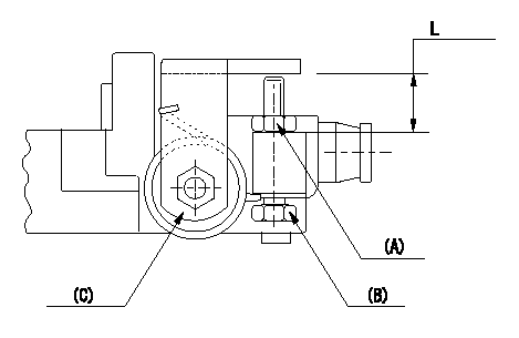
Adjustment of the stop lever
Adjust adjusting bolt (B) so that the starting injection quantity is within the standard.
Fix using nut.
(A) Adjusting nut
(C) Starting injection quantity adjusting lever
----------
----------
L=15.0~18.5mm
----------
----------
L=15.0~18.5mm
Information:
Illustration 70 g03402776
Install 8T-5389 Elbow (12) using 238-5081 O-Ring Seal (11) and 228-7092 O-Ring Seal (13)
Illustration 71 g03701313
Install 6V-8636 Connector (17) using 214-7568 O-Ring Seal (16) and 228-7089 O-Ring Seal (18). Install 128-6841 Elbow (15) using 238-5082 O-Ring Seal (19) and 228-7092 O-Ring Seal (14).
Illustration 72 g03701321
Reconnect 209-5526 Hose As (20) to the fuel transfer pump
Illustration 73 g03701349
Install 387-7154 Tube As (21) and 387-7159 Tube As (22).
Illustration 74 g03701355
Install 416-9706 Fuel Tube (24) using 338-8439 Clip (23).
Install the remaining components that were removed during the HEUI pump replacement procedure.Installation Procedure for 511, 521, 522, 532, 541 and 552 Track Feller Bunchers
Table 10
Required parts for 532, 541, 541B , 551, 552, and 552B Track Feller Bunchers
Part Number Description Quantity
384-0607 Unit Injector Hydraulic Pump Gp 1
227-5904 O-Ring Seal 1
6V-7981 Bolt 2
6V-5839 Washer 2
387-7153 Tube As 1
387-7151 Tube As 1
6V-8629 Elbow 1
238-5081 O-Ring Seal 1
228-7092 O-Ring Seal 2
128-6841 Elbow 1
238-5082 O-Ring Seal 1
6V-8636 Connector 2
228-7089 O-Ring Seal 2
214-7568 O-Ring Seal 3
360-3679 Connector Plug 1
6V-3305 O-Ring Adapter 1
214-7567 O-Ring Seal 2
Illustration 75 g03402944
Install 6V-3305 O-Ring Adapter (2) using 214-7567 O-Ring Seal (1). Also install new 214-7567 O-Ring Seal (1) to injection actuation pressure sensor.
Illustration 76 g03402955
Install 384-0607 Unit Injector Hydraulic Pump Gp (4) using 227-5904 O-Ring Seal (3). If necessary, in order to aid in installation, rotate the pump to an 8 o'clock position when looking at the engine from the rear.
Illustration 77 g03402984
Install new 6V-7981 Bolts (5) and 6V-5839 Washers (6). Torque to 55 10 N m (41 7 lb ft)
Illustration 78 g03701359
Install the 6V-8636 Connector (12) using 214-7568 O-Ring Seal (11) and 228-7089 O-Ring Seal (13). Install 360-3679 Connector Plug (10) using 214-7568 O-Ring Seal (11). Install 6V-8629 Elbow (8) using 238-5081 O-Ring Seal (7) and 228-7092 O-Ring Seal (9).
Illustration 79 g03701379
Install 128-6841 Elbow (15) using 238-5082 O-Ring Seal (19) and 228-7092 O-Ring Seal (14). Install 6V-8636 Connector (17) using 214-7568 O-Ring Seal (16) and 228-7089 O-Ring Seal (18).
Illustration 80 g03701406
Install 387-7151 Tube As (21) and 387-7153 Tube As (20).
Install the remaining components that were removed during the HEUI pump replacement procedure.
Have questions with 104780-9720?
Group cross 104780-9720 ZEXEL
Nissan-Diesel
104780-9720
9 460 614 795
167002S519
INJECTION-PUMP ASSEMBLY
TD27
TD27