Information injection-pump assembly
ZEXEL
104780-9260
1047809260
Rating:
Cross reference number
ZEXEL
104780-9260
1047809260
Zexel num
Bosch num
Firm num
Name
104780-9260
INJECTION-PUMP ASSEMBLY
TD27
TD27
Calibration Data:
Adjustment conditions
Test oil
1404 Test oil ISO4113orSAEJ967d
1404 Test oil ISO4113orSAEJ967d
Test oil temperature
degC
45
45
50
Nozzle
105780-0060
Bosch type code
NP-DN0SD1510
Nozzle holder
105780-2150
Opening pressure
MPa
13
13
13.3
Opening pressure
kgf/cm2
133
133
136
Injection pipe
157805-7320
Injection pipe
Inside diameter - outside diameter - length (mm) mm 2-6-450
Inside diameter - outside diameter - length (mm) mm 2-6-450
Joint assembly
157641-4720
Tube assembly
157641-4020
Transfer pump pressure
kPa
20
20
20
Transfer pump pressure
kgf/cm2
0.2
0.2
0.2
Direction of rotation (viewed from drive side)
Right R
Right R
Injection timing adjustment
Pump speed
r/min
1100
1100
1100
Average injection quantity
mm3/st.
47.5
45
50
Difference in delivery
mm3/st.
4
Basic
*
Oil temperature
degC
50
48
52
Injection timing adjustment_02
Pump speed
r/min
500
500
500
Average injection quantity
mm3/st.
39.3
36.3
42.3
Oil temperature
degC
48
46
50
Injection timing adjustment_03
Pump speed
r/min
1100
1100
1100
Average injection quantity
mm3/st.
47.5
46.5
48.5
Difference in delivery
mm3/st.
4.5
Basic
*
Oil temperature
degC
50
48
52
Injection timing adjustment_04
Pump speed
r/min
2150
2150
2150
Average injection quantity
mm3/st.
44.6
41.6
47.6
Oil temperature
degC
52
50
54
Injection quantity adjustment
Pump speed
r/min
2550
2550
2550
Average injection quantity
mm3/st.
11.7
9.7
13.7
Difference in delivery
mm3/st.
3
Basic
*
Oil temperature
degC
55
52
58
Injection quantity adjustment_02
Pump speed
r/min
2700
2700
2700
Average injection quantity
mm3/st.
5
Oil temperature
degC
55
52
58
Injection quantity adjustment_03
Pump speed
r/min
2350
2350
2350
Average injection quantity
mm3/st.
38.6
33.6
43.6
Oil temperature
degC
52
50
54
Injection quantity adjustment_04
Pump speed
r/min
2550
2550
2550
Average injection quantity
mm3/st.
11.7
9.2
14.2
Basic
*
Oil temperature
degC
55
52
58
Governor adjustment
Pump speed
r/min
350
350
350
Average injection quantity
mm3/st.
7.4
5.4
9.4
Difference in delivery
mm3/st.
2
Basic
*
Oil temperature
degC
48
46
50
Governor adjustment_02
Pump speed
r/min
350
350
350
Average injection quantity
mm3/st.
7.4
4.9
9.9
Difference in delivery
mm3/st.
2.5
Basic
*
Oil temperature
degC
48
46
50
Timer adjustment
Pump speed
r/min
100
100
100
Average injection quantity
mm3/st.
60
45
80
Basic
*
Oil temperature
degC
48
46
50
Remarks
Full
Full
Timer adjustment_02
Pump speed
r/min
100
100
100
Average injection quantity
mm3/st.
60
45
80
Oil temperature
degC
48
46
50
Remarks
Full
Full
Speed control lever angle
Pump speed
r/min
350
350
350
Average injection quantity
mm3/st.
0
0
0
Oil temperature
degC
48
46
50
Remarks
Magnet OFF at idling position
Magnet OFF at idling position
0000000901
Pump speed
r/min
1100
1100
1100
Overflow quantity with S/T ON
cm3/min
390
260
520
Oil temperature
degC
50
48
52
Stop lever angle
Pump speed
r/min
1100
1100
1100
Pressure with S/T ON
kPa
520
481
559
Pressure with S/T ON
kgf/cm2
5.3
4.9
5.7
Pressure with S/T OFF
kPa
432
403
461
Pressure with S/T OFF
kgf/cm2
4.4
4.1
4.7
Basic
*
Oil temperature
degC
50
48
52
Remarks
OFF
OFF
Stop lever angle_02
Pump speed
r/min
1100
1100
1100
Pressure with S/T OFF
kPa
432
393
471
Pressure with S/T OFF
kgf/cm2
4.4
4
4.8
Basic
*
Oil temperature
degC
50
48
52
Remarks
OFF
OFF
Stop lever angle_03
Pump speed
r/min
1700
1700
1700
Pressure with S/T OFF
kPa
559
520
598
Pressure with S/T OFF
kgf/cm2
5.7
5.3
6.1
Oil temperature
degC
50
48
52
0000001101
Pump speed
r/min
1100
1100
1100
Timer stroke with S/T ON
mm
3.5
3.1
3.9
Timer stroke with S/T OFF
mm
1.9
1.7
2.1
Basic
*
Oil temperature
degC
50
48
52
Remarks
OFF
OFF
_02
Pump speed
r/min
850
850
850
Timer stroke with S/T OFF
mm
0.8
0.3
1.3
Oil temperature
degC
50
48
52
_03
Pump speed
r/min
1100
1100
1100
Timer stroke with S/T ON
mm
3.5
3
4
Timer stroke with S/T OFF
mm
1.9
1.6
2.2
Basic
*
Oil temperature
degC
50
48
52
Remarks
OFF
OFF
_04
Pump speed
r/min
1700
1700
1700
Timer stroke with S/T OFF
mm
4.4
3.9
4.9
Oil temperature
degC
50
48
52
_05
Pump speed
r/min
2300
2300
2300
Timer stroke with S/T OFF
mm
6.1
5.6
6.5
Oil temperature
degC
52
50
54
0000001201
Max. applied voltage
V
8
8
8
Test voltage
V
13
12
14
0000001401
Pump speed
r/min
1100
1100
1100
Average injection quantity
mm3/st.
30
29.5
30.5
Timer stroke TA
mm
1.2
1
1.4
Timer stroke variation dT
mm
0.7
0.7
0.7
Basic
*
Oil temperature
degC
50
48
52
Remarks
OFF
OFF
_02
Pump speed
r/min
1100
1100
1100
Average injection quantity
mm3/st.
47.5
46.5
48.5
Timer stroke TA
mm
1.9
1.6
2.2
Oil temperature
degC
50
48
52
_03
Pump speed
r/min
1100
1100
1100
Average injection quantity
mm3/st.
30
29
31
Timer stroke TA
mm
1.2
0.9
1.5
Timer stroke variation dT
mm
0.7
0.7
0.7
Basic
*
Oil temperature
degC
50
48
52
Remarks
OFF
OFF
_04
Pump speed
r/min
1100
1100
1100
Average injection quantity
mm3/st.
21
18.5
23.5
Timer stroke TA
mm
0.6
0.1
1.1
Timer stroke variation dT
mm
1.3
1.3
1.3
Oil temperature
degC
50
48
52
Timing setting
K dimension
mm
3.3
3.2
3.4
KF dimension
mm
5.8
5.7
5.9
MS dimension
mm
0.8
0.7
0.9
Pre-stroke
mm
0.1
0.08
0.12
Control lever angle alpha
deg.
55.5
51.5
59.5
Control lever angle beta
deg.
36
31
41
Test data Ex:
0000001801 POTENTIOMETER ADJUSTMENT
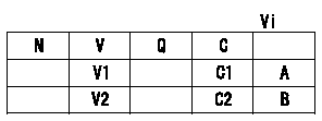
A:Adjusting point
B:Confirmation point
C:Position of the control lever
Vi:Applied voltage
V:Potentiometer output voltage
Q:Injection quantity
C1:Idle
C2:Full speed
----------
----------
V1=1.4+-0.03V V2=Above9.5V Vi=10V
----------
----------
V1=1.4+-0.03V V2=Above9.5V Vi=10V
Information:
Use tool (E) in order to cut off the part of rivet (1) that has been peened. Remove rivet (1) from fuel injection control linkage (4) .
Illustration 13 g00702186
The 180-7951 Bushing Assembly Kit (F) Rack Control Shaft (G) Governor Link (4) Fuel Injection Control Linkage (7) 180-7952 Lever Bushing (8) 8L-5832 Hex Nut (9) 9X-8907 Hexagon Button Screw
Use the 180-7951 Bushing Assembly Kit in order to modify the linkage. Insert 9X-8907 Hexagon Button Screw (9) from the 180-7951 Bushing Assembly Kit into fuel injection control linkage (4). Refer to Illustration 13.
Apply 169-5464 Quick Cure Primer apply on the threads of 9X-8907 Hexagon Button Screw (9) and 8L-5832 Hex Nut (8). Allow the primer to dry. The Quick Cure Primer counteracts the effects of the Volatile Corrosion Inhibitor (VCI) paper that was used to package the parts.
Assemble 180-7952 Lever Bushing (7) on 9X-8907 Hexagon Button Screw (9). Refer to Illustration 13.
Apply the 154-9731 Thread Lock Compound on the threads of 9X-8907 Hexagon Button Screw (9) and 8L-5832 Hex Nut (8) .
Illustration 14 g00655322
Place 8L-5832 Hex Nut (8) on 9X-8907 Hexagon Button Screw (9). Tighten 8L-5832 Hex Nut (8) until hex nut (8) is snug. Tighten 8L-5832 Hex Nut (8) for an additional 180 degrees.
Do not let metal chips or pieces of the rivet fall into the engine.
Illustration 15 g00655325
Clean the fuel injection control linkage and clean the surfaces of the cylinder head that are adjacent to the fuel injection control linkage with shop solvent. Remove the towels and remove all debris very carefully.
Install the 180-7956 Clamp Assembly Kit . Refer to the "Installation Of The 180-7956 Clamp Assembly Kit " section of this publication.Installation Of The 180-7956 Clamp Assembly Kit
Note: The 180-7956 Clamp Assembly Kit is used for the former control linkages only.Note: If the 180-7956 Clamp Assembly Kit is installed, refer to ""Modification of the 128-9640 Injector Synchronization Fixture "".The 180-7956 Clamp Assembly Kit may be installed on the fuel injection control linkage. The 180-7956 Clamp Assembly Kit will increase the strength of the joint.
Illustration 16 g00655326
Install 183-9390 Spacer (10) on fuel injection control linkage (4). Refer to Illustration 16.
Apply 169-5464 Quick Cure Primer to the threaded hole in the 180-7954 Clamp (11). Apply 169-5464 Quick Cure Primer to the threads of screw (13). Allow the primer to dry. The Quick Cure Primer counteracts the effects of the Volatile Corrosion Inhibitor (VCI) paper that was used to package the parts.
Apply 154-9731 Thread Lock Compound to the threaded hole in the 180-7954 Clamp (11). Apply 154-9731 Thread Lock Compound to the threads of screw (13) of clamp assembly. Loosely assemble 180-7954 Clamp (11) and 180-7987 Clamp (12) on fuel injection control linkage (4). Refer to Illustration 16. Be sure that the rivet head or bushing (14) is fully engaged into the counterbore of the
Have questions with 104780-9260?
Group cross 104780-9260 ZEXEL
Nissan
Nissan-Diesel
Nissan-Diesel
Nissan-Diesel
Nissan-Diesel
Nissan-Diesel
104780-9260
INJECTION-PUMP ASSEMBLY
TD27
TD27