Information injection-pump assembly
ZEXEL
104780-9250
1047809250

Rating:
Cross reference number
ZEXEL
104780-9250
1047809250
Zexel num
Bosch num
Firm num
Name
104780-9250
INJECTION-PUMP ASSEMBLY
TD27
TD27
Calibration Data:
Adjustment conditions
Test oil
1404 Test oil ISO4113orSAEJ967d
1404 Test oil ISO4113orSAEJ967d
Test oil temperature
degC
45
45
50
Nozzle
105780-0060
Bosch type code
NP-DN0SD1510
Nozzle holder
105780-2150
Opening pressure
MPa
13
13
13.3
Opening pressure
kgf/cm2
133
133
136
Injection pipe
157805-7320
Injection pipe
Inside diameter - outside diameter - length (mm) mm 2-6-450
Inside diameter - outside diameter - length (mm) mm 2-6-450
Joint assembly
157641-4720
Tube assembly
157641-4020
Transfer pump pressure
kPa
20
20
20
Transfer pump pressure
kgf/cm2
0.2
0.2
0.2
Direction of rotation (viewed from drive side)
Right R
Right R
Injection timing adjustment
Pump speed
r/min
1100
1100
1100
Average injection quantity
mm3/st.
50.5
50
51
Difference in delivery
mm3/st.
4
Basic
*
Oil temperature
degC
50
48
52
Injection timing adjustment_02
Pump speed
r/min
500
500
500
Average injection quantity
mm3/st.
42.3
39.3
45.3
Oil temperature
degC
48
46
50
Injection timing adjustment_03
Pump speed
r/min
1100
1100
1100
Average injection quantity
mm3/st.
50.5
49.5
51.5
Difference in delivery
mm3/st.
4.5
Basic
*
Oil temperature
degC
50
48
52
Injection timing adjustment_04
Pump speed
r/min
2150
2150
2150
Average injection quantity
mm3/st.
47.6
44.6
50.6
Oil temperature
degC
52
50
54
Injection quantity adjustment
Pump speed
r/min
2550
2550
2550
Average injection quantity
mm3/st.
11.7
9.7
13.7
Difference in delivery
mm3/st.
3
Basic
*
Oil temperature
degC
55
52
58
Injection quantity adjustment_02
Pump speed
r/min
2700
2700
2700
Average injection quantity
mm3/st.
5
Oil temperature
degC
55
52
58
Injection quantity adjustment_03
Pump speed
r/min
2350
2350
2350
Average injection quantity
mm3/st.
38.6
33.6
43.6
Oil temperature
degC
52
50
54
Injection quantity adjustment_04
Pump speed
r/min
2550
2550
2550
Average injection quantity
mm3/st.
11.7
9.2
14.2
Basic
*
Oil temperature
degC
55
52
58
Governor adjustment
Pump speed
r/min
350
350
350
Average injection quantity
mm3/st.
7.4
5.4
9.4
Difference in delivery
mm3/st.
2
Basic
*
Oil temperature
degC
48
46
50
Governor adjustment_02
Pump speed
r/min
350
350
350
Average injection quantity
mm3/st.
7.4
4.9
9.9
Difference in delivery
mm3/st.
2.5
Basic
*
Oil temperature
degC
48
46
50
Timer adjustment
Pump speed
r/min
100
100
100
Average injection quantity
mm3/st.
60
45
80
Basic
*
Oil temperature
degC
48
46
50
Remarks
Full
Full
Timer adjustment_02
Pump speed
r/min
100
100
100
Average injection quantity
mm3/st.
60
45
80
Oil temperature
degC
48
46
50
Remarks
Full
Full
Speed control lever angle
Pump speed
r/min
350
350
350
Average injection quantity
mm3/st.
0
0
0
Oil temperature
degC
48
46
50
Remarks
Magnet OFF at idling position
Magnet OFF at idling position
0000000901
Pump speed
r/min
1100
1100
1100
Overflow quantity with S/T ON
cm3/min
390
260
520
Oil temperature
degC
50
48
52
Stop lever angle
Pump speed
r/min
1100
1100
1100
Pressure with S/T ON
kPa
520
481
559
Pressure with S/T ON
kgf/cm2
5.3
4.9
5.7
Pressure with S/T OFF
kPa
432
403
461
Pressure with S/T OFF
kgf/cm2
4.4
4.1
4.7
Basic
*
Oil temperature
degC
50
48
52
Remarks
OFF
OFF
Stop lever angle_02
Pump speed
r/min
1100
1100
1100
Pressure with S/T OFF
kPa
432
393
471
Pressure with S/T OFF
kgf/cm2
4.4
4
4.8
Basic
*
Oil temperature
degC
50
48
52
Remarks
OFF
OFF
Stop lever angle_03
Pump speed
r/min
1700
1700
1700
Pressure with S/T OFF
kPa
559
520
598
Pressure with S/T OFF
kgf/cm2
5.7
5.3
6.1
Oil temperature
degC
50
48
52
0000001101
Pump speed
r/min
1100
1100
1100
Timer stroke with S/T ON
mm
3.5
3.1
3.9
Timer stroke with S/T OFF
mm
1.9
1.7
2.1
Basic
*
Oil temperature
degC
50
48
52
Remarks
OFF
OFF
_02
Pump speed
r/min
850
850
850
Timer stroke with S/T OFF
mm
0.8
0.3
1.3
Oil temperature
degC
50
48
52
_03
Pump speed
r/min
1100
1100
1100
Timer stroke with S/T ON
mm
3.5
3
4
Timer stroke with S/T OFF
mm
1.9
1.6
2.2
Basic
*
Oil temperature
degC
50
48
52
Remarks
OFF
OFF
_04
Pump speed
r/min
1700
1700
1700
Timer stroke with S/T OFF
mm
4.4
3.9
4.9
Oil temperature
degC
50
48
52
_05
Pump speed
r/min
2300
2300
2300
Timer stroke with S/T OFF
mm
6.1
5.6
6.5
Oil temperature
degC
52
50
54
0000001201
Max. applied voltage
V
8
8
8
Test voltage
V
13
12
14
0000001401
Pump speed
r/min
1100
1100
1100
Average injection quantity
mm3/st.
33
32.5
33.5
Timer stroke TA
mm
1.2
1
1.4
Timer stroke variation dT
mm
0.7
0.7
0.7
Basic
*
Oil temperature
degC
50
48
52
Remarks
OFF
OFF
_02
Pump speed
r/min
1100
1100
1100
Average injection quantity
mm3/st.
50.5
49.5
51.5
Timer stroke TA
mm
1.9
1.6
2.2
Oil temperature
degC
50
48
52
_03
Pump speed
r/min
1100
1100
1100
Average injection quantity
mm3/st.
33
32
34
Timer stroke TA
mm
1.2
0.9
1.5
Timer stroke variation dT
mm
0.7
0.7
0.7
Basic
*
Oil temperature
degC
50
48
52
Remarks
OFF
OFF
_04
Pump speed
r/min
1100
1100
1100
Average injection quantity
mm3/st.
24
21.5
26.5
Timer stroke TA
mm
0.6
0.1
1.1
Timer stroke variation dT
mm
1.3
1.3
1.3
Oil temperature
degC
50
48
52
Timing setting
K dimension
mm
3.3
3.2
3.4
KF dimension
mm
5.8
5.7
5.9
MS dimension
mm
0.8
0.7
0.9
Pre-stroke
mm
0.1
0.08
0.12
Control lever angle alpha
deg.
55.5
51.5
59.5
Control lever angle beta
deg.
36
31
41
Test data Ex:
0000001801 POTENTIOMETER ADJUSTMENT
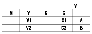
A:Adjusting point
B:Confirmation point
C:Position of the control lever
Vi:Applied voltage
V:Potentiometer output voltage
Q:Injection quantity
C1:Idle
C2:Full speed
----------
----------
V1=1.4+-0.03V V2=Above9.5V Vi=10V
----------
----------
V1=1.4+-0.03V V2=Above9.5V Vi=10V
Information:
Illustration 21 shows the direction the rack moves when the fuel injector is receiving fuel.
Illustration 22 g01455811
Illustration 1 - Flowchart for the Air in Fuel Test (Test F)
Illustration 23 g01455812
Illustration 2 - Flowchart for the Air in Fuel Test (Test F)Fuel Injector Cranking Test (Test G)
Note: The fuel injector cranking test checks for worn out injectors by measuring the cranking rack.
Illustration 24 g01412134
(3) The rack control (4) The number one fuel injectorNote: Refer to Illustration 24 for the location of the rack control and the location of the number one injector.
Illustration 25 g01412115
Flowchart for the Fuel Injector Cranking Test (Test G)Fuel Shutoff Solenoid Test (Test H)
Note: The fuel shutoff solenoid test determines if the fuel shutoff solenoid and wiring harness are operating properly.
Illustration 26 g01412143
Flowchart for the Fuel Shutoff Solenoid Test (Test H)Fuel Ratio Control (FRC) Setting Test (Test I)
Note: The FRC setting test checks the FRC setting.
Illustration 27 g01412145
Flowchart for the Fuel Ratio Control (FRC) Setting Test (Test I)Governor Servo Retaining Ring Test (Test J)
Note: Do not run the engine during this test.Note: The governor servo retaining ring test checks for faulty internal parts of the governor.
Illustration 28 g01422811
(1) Paddle
Illustration 29 g01422821
(2) Clevis pin
Illustration 30 g01412147
Flowchart for the Governor Servo Retaining Ring Test (Test J)Fuel Transfer Pump Test (Test K)
Note: The fuel transfer pump test is a visual inspection of the fuel transfer pump components.
Illustration 31 g01412150
(1) Screen (2) Inlet check valve (3) Spring (4) Bolt (5) Piston (6) Outlet check valve (7) Freeze plug (8) Piston check valve (9) Passage (10) Tappet Assembly (11) CamNote: Refer to Illustration 31 for the location of the components for the fuel transfer pump.
Illustration 32 g01412149
Flowchart for the Fuel Transfer Pump Test (Test K)Fuel Ratio Control (FRC) Diaphragm Leak Test (Test L)
Note: The FRC diaphragm leak test checks for a leaking FRC diaphragm.
Illustration 33 g01412154
Flowchart for the Fuel Ratio Control (FRC) Diaphragm Leak Test (Test L)
Have questions with 104780-9250?
Group cross 104780-9250 ZEXEL
Nissan
Nissan-Diesel
Nissan-Diesel
Nissan-Diesel
Nissan-Diesel
104780-9250
INJECTION-PUMP ASSEMBLY
TD27
TD27