Information injection-pump assembly
BOSCH
9 460 614 784
9460614784
ZEXEL
104780-9211
1047809211
NISSAN-DIESEL
167003S902
167003s902
Rating:
Cross reference number
BOSCH
9 460 614 784
9460614784
ZEXEL
104780-9211
1047809211
NISSAN-DIESEL
167003S902
167003s902
Zexel num
Bosch num
Firm num
Name
104780-9211
9 460 614 784
167003S902 NISSAN-DIESEL
INJECTION-PUMP ASSEMBLY
TD25-TI K
TD25-TI K
Calibration Data:
Adjustment conditions
Test oil
1404 Test oil ISO4113orSAEJ967d
1404 Test oil ISO4113orSAEJ967d
Test oil temperature
degC
45
45
50
Nozzle
105780-0060
Bosch type code
NP-DN0SD1510
Nozzle holder
105780-2150
Opening pressure
MPa
13
13
13.3
Opening pressure
kgf/cm2
133
133
136
Injection pipe
157805-7320
Injection pipe
Inside diameter - outside diameter - length (mm) mm 2-6-450
Inside diameter - outside diameter - length (mm) mm 2-6-450
Joint assembly
157641-4720
Tube assembly
157641-4020
Transfer pump pressure
kPa
20
20
20
Transfer pump pressure
kgf/cm2
0.2
0.2
0.2
Direction of rotation (viewed from drive side)
Right R
Right R
Injection timing adjustment
Pump speed
r/min
500
500
500
Boost pressure
kPa
0
0
0
Boost pressure
kgf/cm2
0
0
0
Boost pressure
mmHg
0
0
0
Average injection quantity
mm3/st.
41.5
41
42
Basic
*
Oil temperature
degC
48
46
50
Remarks
NA
NA
Injection timing adjustment_02
Pump speed
r/min
800
800
800
Boost pressure
kPa
37.3
36
38.6
Boost pressure
kgf/cm2
0.38
0.366
0.394
Boost pressure
mmHg
280
270
290
Average injection quantity
mm3/st.
51.8
51.3
52.3
Basic
*
Oil temperature
degC
50
48
52
Remarks
CBS
CBS
Injection timing adjustment_03
Pump speed
r/min
1000
1000
1000
Boost pressure
kPa
80
78.7
81.3
Boost pressure
kgf/cm2
0.82
0.806
0.834
Boost pressure
mmHg
600
590
610
Average injection quantity
mm3/st.
63.6
63.1
64.1
Difference in delivery
mm3/st.
6
Basic
*
Oil temperature
degC
50
48
52
Remarks
Full
Full
Injection timing adjustment_04
Pump speed
r/min
500
500
500
Boost pressure
kPa
0
0
0
Boost pressure
kgf/cm2
0
0
0
Boost pressure
mmHg
0
0
0
Average injection quantity
mm3/st.
41.5
40.5
42.5
Basic
*
Oil temperature
degC
48
46
50
Remarks
NA
NA
Injection timing adjustment_05
Pump speed
r/min
800
800
800
Boost pressure
kPa
37.3
36
38.6
Boost pressure
kgf/cm2
0.38
0.366
0.394
Boost pressure
mmHg
280
270
290
Average injection quantity
mm3/st.
51.8
50.8
52.8
Basic
*
Oil temperature
degC
50
48
52
Remarks
CBS
CBS
Injection timing adjustment_06
Pump speed
r/min
1000
1000
1000
Boost pressure
kPa
80
78.7
81.3
Boost pressure
kgf/cm2
0.82
0.806
0.834
Boost pressure
mmHg
600
590
610
Average injection quantity
mm3/st.
63.6
62.6
64.6
Difference in delivery
mm3/st.
6.5
Basic
*
Oil temperature
degC
50
48
52
Remarks
Full
Full
Injection timing adjustment_07
Pump speed
r/min
1200
1200
1200
Boost pressure
kPa
80
78.7
81.3
Boost pressure
kgf/cm2
0.82
0.806
0.834
Boost pressure
mmHg
600
590
610
Average injection quantity
mm3/st.
65.3
62.8
67.8
Oil temperature
degC
50
48
52
Injection timing adjustment_08
Pump speed
r/min
1500
1500
1500
Boost pressure
kPa
80
78.7
81.3
Boost pressure
kgf/cm2
0.82
0.806
0.834
Boost pressure
mmHg
600
590
610
Average injection quantity
mm3/st.
65.3
62.3
68.3
Oil temperature
degC
50
48
52
Injection timing adjustment_09
Pump speed
r/min
2000
2000
2000
Boost pressure
kPa
80
78.7
81.3
Boost pressure
kgf/cm2
0.82
0.806
0.834
Boost pressure
mmHg
600
590
610
Average injection quantity
mm3/st.
60.7
57.7
63.7
Oil temperature
degC
50
48
52
Injection quantity adjustment
Pump speed
r/min
2500
2500
2500
Boost pressure
kPa
80
78.7
81.3
Boost pressure
kgf/cm2
0.82
0.806
0.834
Boost pressure
mmHg
600
590
610
Average injection quantity
mm3/st.
16.7
14.7
18.7
Basic
*
Oil temperature
degC
55
52
58
Injection quantity adjustment_02
Pump speed
r/min
2750
2750
2750
Boost pressure
kPa
80
78.7
81.3
Boost pressure
kgf/cm2
0.82
0.806
0.834
Boost pressure
mmHg
600
590
610
Average injection quantity
mm3/st.
5
Oil temperature
degC
55
52
58
Injection quantity adjustment_03
Pump speed
r/min
2250
2250
2250
Boost pressure
kPa
80
78.7
81.3
Boost pressure
kgf/cm2
0.82
0.806
0.834
Boost pressure
mmHg
600
590
610
Average injection quantity
mm3/st.
50.4
50.4
50.4
Oil temperature
degC
52
50
54
Injection quantity adjustment_04
Pump speed
r/min
2500
2500
2500
Boost pressure
kPa
80
78.7
81.3
Boost pressure
kgf/cm2
0.82
0.806
0.834
Boost pressure
mmHg
600
590
610
Average injection quantity
mm3/st.
16.7
13.7
19.7
Basic
*
Oil temperature
degC
55
52
58
Governor adjustment
Pump speed
r/min
350
350
350
Boost pressure
kPa
0
0
0
Boost pressure
kgf/cm2
0
0
0
Boost pressure
mmHg
0
0
0
Average injection quantity
mm3/st.
9.4
7.4
11.4
Difference in delivery
mm3/st.
2
Basic
*
Oil temperature
degC
48
46
50
Governor adjustment_02
Pump speed
r/min
350
350
350
Boost pressure
kPa
0
0
0
Boost pressure
kgf/cm2
0
0
0
Boost pressure
mmHg
0
0
0
Average injection quantity
mm3/st.
9.4
6.9
11.9
Difference in delivery
mm3/st.
2.5
Basic
*
Oil temperature
degC
48
46
50
Timer adjustment
Pump speed
r/min
100
100
100
Boost pressure
kPa
0
0
0
Boost pressure
kgf/cm2
0
0
0
Boost pressure
mmHg
0
0
0
Average injection quantity
mm3/st.
75
60
95
Basic
*
Oil temperature
degC
48
46
50
Remarks
Full
Full
Timer adjustment_02
Pump speed
r/min
100
100
100
Boost pressure
kPa
0
0
0
Boost pressure
kgf/cm2
0
0
0
Boost pressure
mmHg
0
0
0
Average injection quantity
mm3/st.
75
60
95
Oil temperature
degC
48
46
50
Remarks
Full
Full
Speed control lever angle
Pump speed
r/min
350
350
350
Boost pressure
kPa
0
0
0
Boost pressure
kgf/cm2
0
0
0
Boost pressure
mmHg
0
0
0
Average injection quantity
mm3/st.
0
0
0
Oil temperature
degC
48
46
50
Remarks
Magnet OFF at idling position
Magnet OFF at idling position
0000000901
Pump speed
r/min
1100
1100
1100
Boost pressure
kPa
80
78.7
81.3
Boost pressure
kgf/cm2
0.82
0.806
0.834
Boost pressure
mmHg
600
590
610
Overflow quantity with S/T ON
cm3/min
450
320
580
Oil temperature
degC
50
48
52
Stop lever angle
Pump speed
r/min
1100
1100
1100
Boost pressure
kPa
80
78.7
81.3
Boost pressure
kgf/cm2
0.82
0.806
0.834
Boost pressure
mmHg
600
590
610
Pressure with S/T ON
kPa
510
471
549
Pressure with S/T ON
kgf/cm2
5.2
4.8
5.6
Pressure with S/T OFF
kPa
432
403
461
Pressure with S/T OFF
kgf/cm2
4.4
4.1
4.7
Basic
*
Oil temperature
degC
50
48
52
Remarks
OFF
OFF
Stop lever angle_02
Pump speed
r/min
1100
1100
1100
Boost pressure
kPa
80
78.7
81.3
Boost pressure
kgf/cm2
0.82
0.806
0.834
Boost pressure
mmHg
600
590
610
Pressure with S/T OFF
kPa
432
393
471
Pressure with S/T OFF
kgf/cm2
4.4
4
4.8
Basic
*
Oil temperature
degC
50
48
52
Remarks
OFF
OFF
Stop lever angle_03
Pump speed
r/min
2150
2150
2150
Boost pressure
kPa
80
78.7
81.3
Boost pressure
kgf/cm2
0.82
0.806
0.834
Boost pressure
mmHg
600
590
610
Pressure with S/T OFF
kPa
647
608
686
Pressure with S/T OFF
kgf/cm2
6.6
6.2
7
Oil temperature
degC
52
50
54
0000001101
Pump speed
r/min
1100
1100
1100
Boost pressure
kPa
80
78.7
81.3
Boost pressure
kgf/cm2
0.82
0.806
0.834
Boost pressure
mmHg
600
590
610
Timer stroke with S/T ON
mm
3.8
3.4
4.2
Timer stroke with S/T OFF
mm
2
1.8
2.2
Basic
*
Oil temperature
degC
50
48
52
Remarks
OFF
OFF
_02
Pump speed
r/min
700
700
700
Boost pressure
kPa
80
78.7
81.3
Boost pressure
kgf/cm2
0.82
0.806
0.834
Boost pressure
mmHg
600
590
610
Timer stroke with S/T OFF
mm
0.8
Oil temperature
degC
50
48
52
_03
Pump speed
r/min
1100
1100
1100
Boost pressure
kPa
80
78.7
81.3
Boost pressure
kgf/cm2
0.82
0.806
0.834
Boost pressure
mmHg
600
590
610
Timer stroke with S/T ON
mm
3.8
3.3
4.3
Timer stroke with S/T OFF
mm
2
1.7
2.3
Basic
*
Oil temperature
degC
50
48
52
Remarks
OFF
OFF
_04
Pump speed
r/min
2150
2150
2150
Boost pressure
kPa
80
78.7
81.3
Boost pressure
kgf/cm2
0.82
0.806
0.834
Boost pressure
mmHg
600
590
610
Timer stroke with S/T ON
mm
7.8
7.3
8.2
Timer stroke with S/T OFF
mm
6.9
6.3
7.5
Oil temperature
degC
52
50
54
0000001201
Max. applied voltage
V
8
8
8
Test voltage
V
13
12
14
0000001401
Pump speed
r/min
1100
1100
1100
Boost pressure
kPa
80
78.7
81.3
Boost pressure
kgf/cm2
0.82
0.806
0.834
Boost pressure
mmHg
600
590
610
Average injection quantity
mm3/st.
44
43.5
44.5
Timer stroke TA
mm
1.7
1.7
1.7
Timer stroke variation dT
mm
0.3
0.1
0.5
Basic
*
Oil temperature
degC
50
48
52
Remarks
OFF
OFF
_02
Pump speed
r/min
1100
1100
1100
Boost pressure
kPa
80
78.7
81.3
Boost pressure
kgf/cm2
0.82
0.806
0.834
Boost pressure
mmHg
600
590
610
Average injection quantity
mm3/st.
44
43
45
Timer stroke TA
mm
1.7
1.7
1.7
Timer stroke variation dT
mm
0.3
0
0.6
Basic
*
Oil temperature
degC
50
48
52
Remarks
OFF
OFF
_03
Pump speed
r/min
1100
1100
1100
Boost pressure
kPa
80
78.7
81.3
Boost pressure
kgf/cm2
0.82
0.806
0.834
Boost pressure
mmHg
600
590
610
Average injection quantity
mm3/st.
32
29.5
34.5
Timer stroke TA
mm
1.1
1.1
1.1
Timer stroke variation dT
mm
0.9
0.5
1.3
Oil temperature
degC
50
48
52
Timing setting
K dimension
mm
3.3
3.2
3.4
KF dimension
mm
5.8
5.7
5.9
MS dimension
mm
0.7
0.6
0.8
BCS stroke
mm
4.5
4.3
4.7
Pre-stroke
mm
0.1
0.08
0.12
Control lever angle alpha
deg.
55.5
51.5
59.5
Control lever angle beta
deg.
36
31
41
Test data Ex:
0000001801 POTENTIOMETER ADJUSTMENT
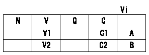
A:Adjusting point
B:Confirmation point
C:Position of the control lever
Vi:Applied voltage
V:Potentiometer output voltage
Q:Injection quantity
C1:Idle
C2:Full speed
----------
----------
V1=1.4+-0.03V V2=Above9.5V Vi=10V
----------
----------
V1=1.4+-0.03V V2=Above9.5V Vi=10V
Information:
General Recommendations and Contamination Control Guidelines for Fuels
Follow all applicable industry standards and all applicable governmental, environmental, and safety guidelines, practices, regulations, and mandates.Note: These general recommendations and guidelines concerning maintenance and care of fuel and fuel storage systems are not intended to be all inclusive. Discuss proper fuel safety and health, handling, and maintenance practices with your fuel supplier. Use of these general recommendations and guidelines does not lessen the engine owners and/or fuel supplier responsibility to follow all industry standard practices for fuel storage and for fuel handling.Note: Where recommendations for draining water and/or sediment and/or debris are stated, dispose of this waste according to all applicable regulations and mandates.Note: Caterpillar filters are designed and built to provide optimal performance and protection of the fuel system components.Clean fuels, as detailed below, are strongly recommended to allow optimal performance and durability of the fuel systems and to reduce power loss, failures, and related down time of engines.Fuels of “ISO 18/16/13” cleanliness levels or cleaner as dispensed into the engine or machine fuel tank should be used. Reduced power, failures and related downtime can result if clean fuels are not used. Fuels of “ISO 18/16/13” are particularly important for new fuel system designs such as Common Rail injection systems and unit injection systems. These new injection system designs utilize higher fuel pressures and are designed with tight clearances between moving parts to meet required stringent emissions regulations. Peak injection pressures in current fuel injection systems may exceed 30,000 psi. Clearances in these systems are less than 5 µm. As a result, particle contaminants as small as 4 µm can cause scoring and scratching of internal pump and injector surfaces and of injector nozzles.Water in the fuel causes cavitation, corrosion of fuel system parts, and provides an environment where microbial growth in the fuel can flourish. Other sources of fuel contamination are soaps, gels, or other compounds that may result from undesirable chemical interactions in the fuels. Gels and other insoluble compounds can also form in biodiesel fuel at low temperatures or if biodiesel is stored for extended periods. An indication of microbial contamination, detrimental fuel additives interactions, or cold temperature gel is very rapid filter plugging of bulk fuel filters or machine fuel filters.To reduce downtime due to contamination, follow these fuel maintenance guidelines in addition to the recommendations given in the "Contamination Control" Chapter in this Special Publication:
Use high-quality fuels per recommended and required specifications (refer to the “Fuel” chapter in this Special Publication).
Do not add new engine oil, waste engine oil or any oil product to the fuel unless the engine is designed and certified to burn diesel engine oil (for example Caterpillar ORS designed for large engines). Engine oils may raise the sulfur level of the fuel and may cause fouling of the fuel system and loss of performance. Engine oils in fuels can also reduce the maintenance intervals of aftertreatment devices in Tier 4 machines.
Use recommended Cat filtration products, including Cat Advanced Efficiency Fuel
Have questions with 104780-9211?
Group cross 104780-9211 ZEXEL
Nissan
Nissan-Diesel
Nissan-Diesel
104780-9211
9 460 614 784
167003S902
INJECTION-PUMP ASSEMBLY
TD25-TI
TD25-TI