Information injection-pump assembly
BOSCH
9 460 614 780
9460614780
ZEXEL
104780-9090
1047809090
NISSAN-DIESEL
1670084K02
1670084k02
Rating:
Cross reference number
BOSCH
9 460 614 780
9460614780
ZEXEL
104780-9090
1047809090
NISSAN-DIESEL
1670084K02
1670084k02
Zexel num
Bosch num
Firm num
Name
104780-9090
9 460 614 780
1670084K02 NISSAN-DIESEL
INJECTION-PUMP ASSEMBLY
TD27 K
TD27 K
Calibration Data:
Adjustment conditions
Test oil
1404 Test oil ISO4113orSAEJ967d
1404 Test oil ISO4113orSAEJ967d
Test oil temperature
degC
45
45
50
Nozzle
105780-0060
Bosch type code
NP-DN0SD1510
Nozzle holder
105780-2150
Opening pressure
MPa
13
13
13.3
Opening pressure
kgf/cm2
133
133
136
Injection pipe
157805-7320
Injection pipe
Inside diameter - outside diameter - length (mm) mm 2-6-450
Inside diameter - outside diameter - length (mm) mm 2-6-450
Joint assembly
157641-4720
Tube assembly
157641-4020
Transfer pump pressure
kPa
20
20
20
Transfer pump pressure
kgf/cm2
0.2
0.2
0.2
Direction of rotation (viewed from drive side)
Right R
Right R
Injection timing adjustment
Pump speed
r/min
1150
1150
1150
Average injection quantity
mm3/st.
49
48.5
49.5
Difference in delivery
mm3/st.
3
Basic
*
Oil temperature
degC
50
48
52
Injection timing adjustment_02
Pump speed
r/min
400
400
400
Average injection quantity
mm3/st.
41.8
41.8
41.8
Oil temperature
degC
48
46
50
Injection timing adjustment_03
Pump speed
r/min
500
500
500
Average injection quantity
mm3/st.
43.3
43.3
43.3
Oil temperature
degC
48
46
50
Injection timing adjustment_04
Pump speed
r/min
700
700
700
Average injection quantity
mm3/st.
46.5
46.5
46.5
Oil temperature
degC
50
48
52
Injection timing adjustment_05
Pump speed
r/min
900
900
900
Average injection quantity
mm3/st.
47.4
47.4
47.4
Oil temperature
degC
50
48
52
Injection timing adjustment_06
Pump speed
r/min
1150
1150
1150
Average injection quantity
mm3/st.
49
48
50
Difference in delivery
mm3/st.
3.5
Basic
*
Oil temperature
degC
50
48
52
Injection timing adjustment_07
Pump speed
r/min
1350
1350
1350
Average injection quantity
mm3/st.
48.1
44.6
51.6
Oil temperature
degC
50
48
52
Injection quantity adjustment
Pump speed
r/min
1500
1500
1500
Average injection quantity
mm3/st.
15.5
12.5
18.5
Basic
*
Oil temperature
degC
50
48
52
Injection quantity adjustment_02
Pump speed
r/min
1650
1650
1650
Average injection quantity
mm3/st.
3
Basic
*
Oil temperature
degC
50
48
52
Injection quantity adjustment_03
Pump speed
r/min
1500
1500
1500
Average injection quantity
mm3/st.
15.5
12
19
Oil temperature
degC
50
48
52
Governor adjustment
Pump speed
r/min
400
400
400
Average injection quantity
mm3/st.
8.3
6.3
10.3
Difference in delivery
mm3/st.
2
Basic
*
Oil temperature
degC
48
46
50
Governor adjustment_02
Pump speed
r/min
400
400
400
Average injection quantity
mm3/st.
8.3
5.8
10.8
Difference in delivery
mm3/st.
2.5
Basic
*
Oil temperature
degC
48
46
50
Timer adjustment
Pump speed
r/min
100
100
100
Average injection quantity
mm3/st.
60
55
65
Basic
*
Oil temperature
degC
48
46
50
Timer adjustment_02
Pump speed
r/min
100
100
100
Average injection quantity
mm3/st.
60
55
65
Basic
*
Oil temperature
degC
48
46
50
Speed control lever angle
Pump speed
r/min
350
350
350
Average injection quantity
mm3/st.
0
0
0
Oil temperature
degC
48
46
50
Remarks
Magnet OFF at idling position
Magnet OFF at idling position
0000000901
Pump speed
r/min
900
900
900
Overflow quantity
cm3/min
410
280
540
Oil temperature
degC
50
48
52
Stop lever angle
Pump speed
r/min
900
900
900
Pressure
kPa
392
363
421
Pressure
kgf/cm2
4
3.7
4.3
Basic
*
Oil temperature
degC
50
48
52
Stop lever angle_02
Pump speed
r/min
900
900
900
Pressure
kPa
392
353
431
Pressure
kgf/cm2
4
3.6
4.4
Basic
*
Oil temperature
degC
50
48
52
Stop lever angle_03
Pump speed
r/min
1100
1100
1100
Pressure
kPa
432
393
471
Pressure
kgf/cm2
4.4
4
4.8
Oil temperature
degC
50
48
52
0000001101
Pump speed
r/min
900
900
900
Timer stroke
mm
2
1.8
2.2
Basic
*
Oil temperature
degC
50
48
52
_02
Pump speed
r/min
900
900
900
Timer stroke
mm
2
1.6
2.4
Basic
*
Oil temperature
degC
50
48
52
_03
Pump speed
r/min
1100
1100
1100
Timer stroke
mm
2.9
2.3
3.5
Oil temperature
degC
50
48
52
_04
Pump speed
r/min
1250
1250
1250
Timer stroke
mm
3.3
2.8
3.7
Oil temperature
degC
50
48
52
0000001201
Max. applied voltage
V
8
8
8
Test voltage
V
13
12
14
Timing setting
K dimension
mm
3.3
3.2
3.4
KF dimension
mm
5.8
5.7
5.9
MS dimension
mm
1.8
1.7
1.9
Pre-stroke
mm
0.1
0.08
0.12
Control lever angle alpha
deg.
54
50
58
Control lever angle beta
deg.
35
30
40
Test data Ex:
0000001801 POTENTIOMETER ADJUSTMENT
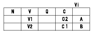
A:Adjusting point
B:Confirmation point
C:Position of the control lever
Vi:Applied voltage
V:Potentiometer output voltage
Q:Injection quantity
C1:Idle
C2:Full speed
----------
----------
V1=7.5+-0.03V V2=(1.6)V Vi=10V
----------
----------
V1=7.5+-0.03V V2=(1.6)V Vi=10V
0000001901 STOP LEVER ADJUSTMENT
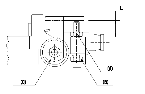
Adjustment of the stop lever
Adjust adjusting bolt (B) so that the starting injection quantity is within the standard.
Fix using nut.
(A) Adjusting nut
(C) Starting injection quantity adjusting lever
----------
----------
L=15.0~18.5mm
----------
----------
L=15.0~18.5mm
Information:
Illustration 39 g00367353
Set the drive speed to "Col 4". Place a straight edge across the opening in the shutdown rod and the shutdown rod nut (F). Use a 7/16 inch open end wrench in order to turn the shutdown rod nut (F) counterclockwise until the governor begins to shut down. Once the governor begins to shut down, turn the nut clockwise one full turn.Adjustment Of The Shutdown Device
Note: The electric shutdown device and the pressure shutdown device should be checked prior to the installation, after the installation, and at 1000 hour intervals thereafter.
Failure to test, inspect and maintain these items could result in faulty operation and possible severe engine damage if an emergency shutdown situation occurs.
The electric shutdown is either an Energize-To-Shutoff (ETS) or an Energize-To-Run (ETR). Identify the type of shutdown device in your governor, and make a note of the type of shutdown device.
Visually inspect the pressure shutdown components for signs of burrs, nicks, scoring and/or wear. Repair the components if evidence of a problem exists. Inspect the pressure shutdown gasket. Determine if the gasket is reusable. If necessary, replace the gasket.
Illustration 40 g00367319
(F) Shutdown Rod Nut. (J) Shutdown Rod. (II) Solenoid. (JJ) Jam Nut. (KK) Set Screw. (LL) Shutdown Plunger. (MM) Solenoid Plunger. (NN) Pivot Pin. (PP) Shutdown Lever.
Visually inspect the electric shutdown device and determine if there is any component wear. If the shutdown is an ETS version, pay particular attention to the connection of the shutdown solenoid's plunger and the shutdown lever's link pin.If there is evidence of wear, replace the solenoid. Inspect the gasket on the electric shutdown. Determine if the gasket is reusable. If necessary, replace the gasket.Check the size of spacer on the solenoid plunger in the electric shutdown. Refer to the Service Magazine Article November 19,, "Field Replacement of Spacer to Correct Possible Sticking in Woodward 3161 Governor Electric Shutoff Group".Adjustment Of The Electric Shutdown Solenoid
Energize-To-Shutoff (ETS)
Place the housing of the electric shutdown in a vise. Use copper jaws or shop towels in order to protect the sides of the aluminum die cast housing. Do NOT excessively tighten the vise.Loosen the jam nut (JJ) that holds the solenoid in the electric shutdown's housing. Remove the solenoid coil (II) in order to expose the shutdown plunger (MM) .Note: Loctite 222 is used on the threads of the solenoid coil during manufacturing. In addition, the jam nut is tightened to a torque of 75 N m (55.5 lb ft).
Carefully clean any dirt, metal filings or metal chips from the solenoid plunger and from the cavity in the solenoid coil. Turn the jam nut on the solenoid coil so that the nut will not interfere with the adjustment of the solenoid coil. Reinstall the solenoid coil in the electric shutdown's housing by turning the coil four times.
Hold the housing and the gasket on a
Have questions with 104780-9090?
Group cross 104780-9090 ZEXEL
Nissan-Diesel
Nissan-Diesel
Nissan
Nissan-Diesel
Nissan
Nissan-Diesel
Nissan
Nissan-Diesel
Dpico
Nissan-Diesel
Nissan
Nissan-Diesel
104780-9090
9 460 614 780
1670084K02
INJECTION-PUMP ASSEMBLY
TD27
TD27