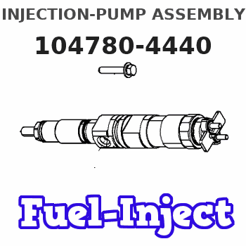
Information injection-pump assembly
BOSCH
9 460 611 644
9460611644
ZEXEL
104780-4440
1047804440
NISSAN-DIESEL
167006T072
167006t072
Rating:
Components :
| 0. | INJECTION-PUMP ASSEMBLY | 104780-4440 |
| 1. | _ | |
| 2. | FUEL INJECTION PUMP | 104680-4440 |
| 3. | NUMBER PLATE | |
| 4. | _ | |
| 5. | CAPSULE | |
| 6. | ADJUSTING DEVICE | |
| 7. | NOZZLE AND HOLDER ASSY | 105148-1221 |
| 8. | Nozzle and Holder | 16600-63G01 |
| 9. | Open Pre:MPa(Kqf/cm2) | 9.8{100} |
| 10. | NOZZLE-HOLDER | 105078-0050 |
| 11. | NOZZLE | 105007-1210 |
Scheme ###:
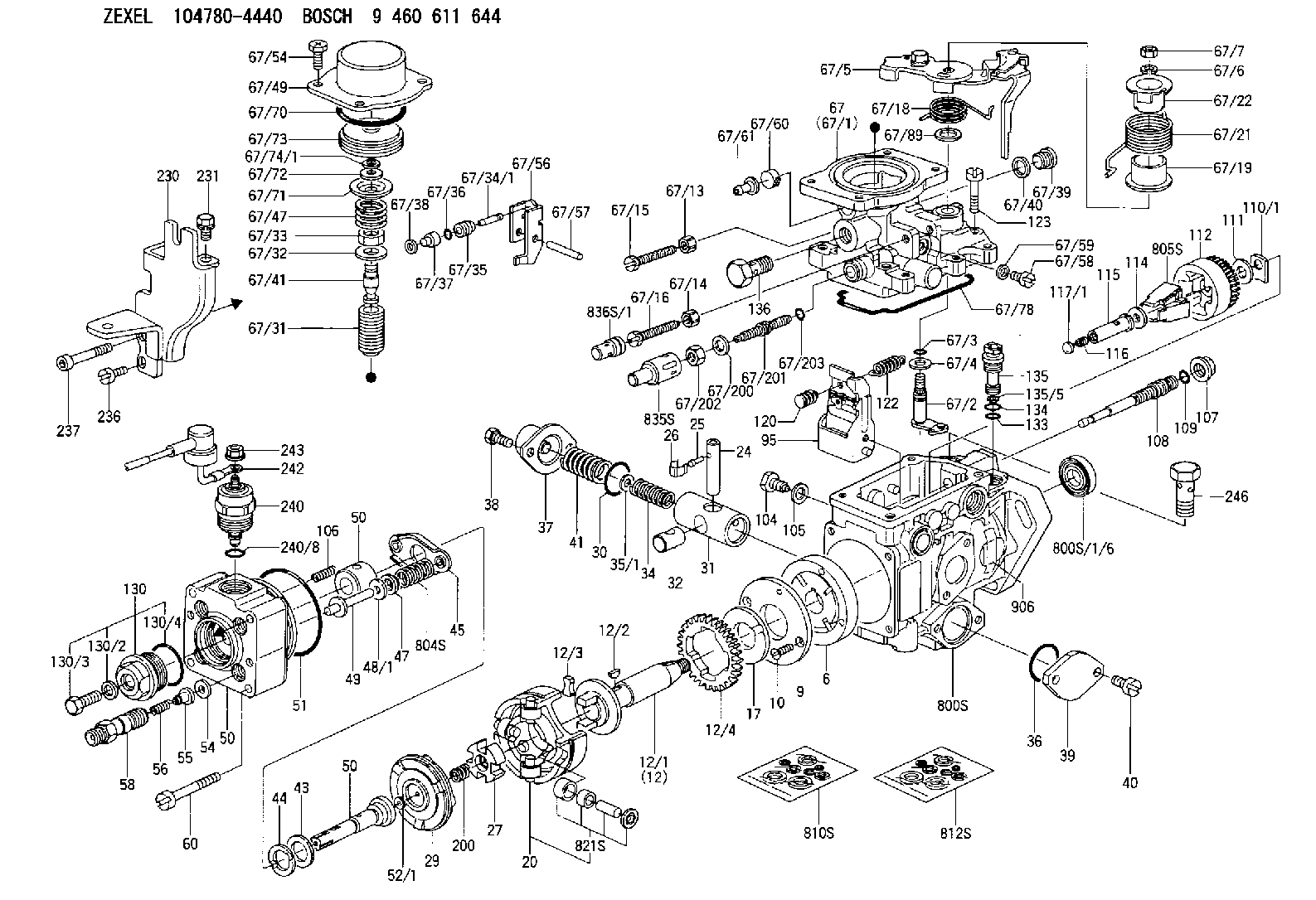
| 1/6. | [1] | 146601-0900 | PACKING RING |
| 6. | [1] | 146100-0420 | SUPPLY PUMP |
| 9. | [1] | 146103-0100 | COVER |
| 10. | [2] | 139104-0000 | FLAT-HEAD SCREW |
| 12. | [1] | 146200-0020 | DRIVE SHAFT |
| 12/1. | [1] | 146200-0000 | DRIVE SHAFT |
| 12/2. | [1] | 146201-0000 | WOODRUFF KEY |
| 12/3. | [2] | 146202-0100 | DAMPER |
| 12/4. | [1] | 146203-0000 | TOOTHED GEAR |
| 17. | [1] | 146204-0000 | PLAIN WASHER |
| 20. | [1] | 146210-2320 | ROLLER SET |
| 24. | [1] | 146303-0000 | BEARING PIN |
| 25. | [1] | 146304-0000 | BEARING PIN |
| 26. | [1] | 146305-0000 | CLAMPING BAND |
| 27. | [1] | 146205-0000 | SLOTTED WASHER |
| 29. | [1] | 146220-2120 | CAM PLATE |
| 30. | [1] | 146600-0800 | O-RING |
| 31. | [1] | 146311-5920 | PUMP PLUNGER |
| 32. | [1] | 146301-0000 | SLIDING PIECE |
| 34. | [1] | 146312-2900 | COMPRESSION SPRING |
| 34B. | [1] | 146312-3000 | COMPRESSION SPRING |
| 34C. | [1] | 146312-1800 | COMPRESSION SPRING |
| 35/1. | [1] | 146690-3200 | SHIM D11.5&9.4T0.1 |
| 35/1. | [1] | 146690-3300 | SHIM D11.5&9.4T0.2 |
| 35/1. | [1] | 146690-3400 | SHIM D11.5&9.4T0.25 |
| 35/1. | [1] | 146690-3500 | SHIM D11.5&9.4T1.0 |
| 35/1. | [1] | 146690-4100 | SHIM D11.5&9.4T2 |
| 35/1. | [1] | 146690-4200 | SHIM D11.5&9.4T0.5 |
| 35/1. | [1] | 146690-4300 | SHIM D11.5&9.4T0.75 |
| 36. | [1] | 146600-0800 | O-RING |
| 37. | [1] | 146310-4020 | COVER |
| 38. | [2] | 146620-5000 | BLEEDER SCREW |
| 39. | [1] | 146310-0100 | COVER |
| 40. | [2] | 146620-5000 | BLEEDER SCREW |
| 41. | [1] | 146312-1900 | COMPRESSION SPRING |
| 43. | [1] | 146230-0000 | SHIM |
| 44. | [1] | 146230-0100 | PLAIN WASHER |
| 45. | [1] | 146231-0001 | SLOTTED WASHER |
| 47. | [2] | 146233-0000 | SLOTTED WASHER |
| 48/1. | [1] | 146603-0100 | SHIM D17.0&5.2T0.80 |
| 48/1. | [1] | 146603-0200 | SHIM D17.0&5.2T1.00 |
| 48/1. | [1] | 146603-0300 | SHIM D17.0&5.2T1.20 |
| 48/1. | [1] | 146603-0400 | SHIM D17.0&5.2T1.50 |
| 48/1. | [1] | 146690-1400 | SHIM D17&5.2T0.9 |
| 48/1. | [1] | 146690-1500 | SHIM D17&5.2T1.1 |
| 48/1. | [1] | 146690-1600 | SHIM D17&5.2T1.3 |
| 48/1. | [1] | 146690-1700 | SHIM D17&5.2T1.4 |
| 48/1. | [1] | 146690-1800 | SHIM D17&5.2T1.6 |
| 49. | [2] | 146234-0500 | GUIDE PIN |
| 50. | [1] | 146401-3720 | HYDRAULIC HEAD |
| 50. | [1] | 146401-3720 | HYDRAULIC HEAD |
| 50. | [1] | 146401-3720 | HYDRAULIC HEAD |
| 51. | [1] | 146600-0000 | O-RING |
| 52/1. | [1] | 146420-0700 | SHIM D9.5&3.0T2.04 |
| 52/1. | [1] | 146420-0800 | SHIM D9.5&3.0T2.06 |
| 52/1. | [1] | 146420-0900 | SHIM D9.5&3.0T2.08 |
| 52/1. | [1] | 146420-1000 | SHIM D9.5&3.0T2.10 |
| 52/1. | [1] | 146420-1100 | SHIM D9.5&3.0T2.12 |
| 52/1. | [1] | 146420-1200 | SHIM D9.5&3.0T2.14 |
| 52/1. | [1] | 146420-1300 | SHIM D9.5&3.0T2.16 |
| 52/1. | [1] | 146420-1400 | SHIM D9.5&3.0T2.18 |
| 52/1. | [1] | 146420-1500 | SHIM D9.5&3.0T2.20 |
| 52/1. | [1] | 146420-1600 | SHIM D9.5&3.0T2.22 |
| 52/1. | [1] | 146420-1700 | SHIM D9.5&3.0T2.24 |
| 52/1. | [1] | 146420-1800 | SHIM D9.5&3.0T2.26 |
| 52/1. | [1] | 146420-1900 | SHIM D9.5&3.0T2.28 |
| 52/1. | [1] | 146420-2000 | SHIM D9.5&3.0T2.30 |
| 52/1. | [1] | 146420-2100 | SHIM D9.5&3.0T2.32 |
| 52/1. | [1] | 146420-2200 | SHIM D9.5&3.0T2.34 |
| 52/1. | [1] | 146420-2400 | SHIM D9.5&3.0T2.38 |
| 52/1. | [1] | 146420-2500 | SHIM D9.5&3.0T2.40 |
| 52/1. | [1] | 146420-2600 | SHIM D9.5&3.0T2.42 |
| 52/1. | [1] | 146420-2700 | SHIM D9.5&3.0T2.44 |
| 52/1. | [1] | 146420-2800 | SHIM D9.5&3.0T2.46 |
| 52/1. | [1] | 146420-2900 | SHIM D9.5&3.0T2.48 |
| 52/1. | [1] | 146420-3000 | SHIM D9.5&3.0T2.50 |
| 52/1. | [1] | 146420-3100 | SHIM D9.5&3.0T2.52 |
| 52/1. | [1] | 146420-3200 | SHIM D9.5&3.0T2.54 |
| 52/1. | [1] | 146420-3300 | SHIM D9.5&3.0T2.56 |
| 52/1. | [1] | 146420-3400 | SHIM D9.5&3.0T2.58 |
| 52/1. | [1] | 146420-3500 | SHIM D9.5&3.0T2.60 |
| 52/1. | [1] | 146420-3600 | SHIM D9.5&3.0T2.62 |
| 52/1. | [1] | 146420-3700 | SHIM D9.5&3.0T2.64 |
| 52/1. | [1] | 146420-3800 | SHIM D9.5&3.0T2.66 |
| 52/1. | [1] | 146420-3900 | SHIM D9.5&3.0T2.68 |
| 52/1. | [1] | 146420-4000 | SHIM D9.5&3.0T2.70 |
| 52/1. | [1] | 146420-4100 | SHIM D9.5&3.0T2.72 |
| 54. | [4] | 146433-0100 | GASKET |
| 55. | [4] | 146430-0320 | DELIVERY-VALVE ASSEMBLY VE4 |
| 56. | [4] | 146432-0000 | COMPRESSION SPRING |
| 58. | [4] | 146440-0220 | FITTING |
| 60. | [3] | 139106-0100 | FLAT-HEAD SCREW |
| 67. | [1] | 146706-4720 | ANEROID CAPSULE |
| 67/1. | [1] | 146508-9921 | GOVERNOR COVER |
| 67/2. | [1] | 146515-3620 | CONTROL SHAFT |
| 67/3. | [1] | 146600-0100 | O-RING |
| 67/4. | [1] | 139310-0200 | PLAIN WASHER |
| 67/5. | [1] | 146537-7320 | CONTROL LEVER |
| 67/6. | [1] | 014110-6440 | LOCKING WASHER D12.2&6.1T1.5 |
| 67/7. | [1] | 013020-6040 | UNION NUT |
| 67/13. | [1] | 139206-0100 | UNION NUT |
| 67/14. | [1] | 146621-1700 | UNION NUT |
| 67/15. | [1] | 146526-4200 | BLEEDER SCREW |
| 67/16. | [1] | 146526-3000 | BLEEDER SCREW |
| 67/18. | [1] | 146587-6900 | COILED SPRING |
| 67/19. | [1] | 146541-3000 | BUSHING |
| 67/21. | [1] | 146587-6800 | COILED SPRING |
| 67/22. | [1] | 146541-3100 | SLOTTED WASHER |
| 67/31. | [1] | 146710-0400 | BUSHING |
| 67/32. | [1] | 146602-1800 | PLAIN WASHER |
| 67/33. | [1] | 146716-0200 | UNION NUT |
| 67/34/1. | [1] | 146713-3000 | ADJUSTING PIN L24.6 |
| 67/34/1. | [1] | 146713-3100 | ADJUSTING PIN L24.8 |
| 67/34/1. | [1] | 146713-3200 | ADJUSTING PIN L25.0 |
| 67/34/1. | [1] | 146713-3300 | ADJUSTING PIN L25.2 |
| 67/34/1. | [1] | 146713-3400 | ADJUSTING PIN L25.4 |
| 67/35. | [1] | 146621-0300 | UNION NUT |
| 67/36. | [1] | 146600-1400 | O-RING |
| 67/37. | [1] | 146710-0100 | BUSHING |
| 67/38. | [1] | 139506-0200 | GASKET |
| 67/39. | [1] | 146620-0300 | CAPSULE |
| 67/40. | [1] | 026512-1540 | GASKET |
| 67/41. | [1] | 146713-2400 | ADJUSTING PIN |
| 67/47. | [1] | 146717-0200 | COILED SPRING |
| 67/49. | [1] | 146721-0700 | COVER |
| 67/54. | [4] | 139006-4400 | BLEEDER SCREW |
| 67/56. | [1] | 146723-0300 | CONTROL LEVER |
| 67/57. | [1] | 146712-0100 | BEARING PIN |
| 67/58. | [2] | 146620-0600 | CAPSULE |
| 67/59. | [2] | 026506-1040 | GASKET |
| 67/60. | [1] | 146724-0300 | ELEMENT |
| 67/61. | [1] | 146724-0400 | CAPSULE |
| 67/70. | [1] | 016520-6010 | O-RING |
| 67/71. | [1] | 146714-0100 | SLOTTED WASHER |
| 67/72. | [1] | 016010-0920 | LOCKING WASHER |
| 67/73. | [1] | 146715-0120 | BELLOWS |
| 67/74/1. | [0] | 146603-3700 | SHIM T0.20 |
| 67/74/1. | [0] | 146603-3800 | SHIM T0.30 |
| 67/74/1. | [0] | 146603-3900 | SHIM T0.50 |
| 67/74/1. | [0] | 146603-4000 | SHIM T0.70 |
| 67/74/1. | [0] | 146603-4100 | SHIM T1.00 |
| 67/74/1. | [0] | 146603-4200 | SHIM T1.50 |
| 67/78. | [1] | 146600-4400 | SEAL RING |
| 67/89. | [1] | 146541-4900 | PLAIN WASHER |
| 67/200. | [1] | 139308-0300 | PLAIN WASHER |
| 67/201. | [1] | 146545-3400 | THREADED PIN L53.00 |
| 67/201B. | [1] | 146545-3500 | THREADED PIN L55.00 |
| 67/201C. | [1] | 146545-3600 | THREADED PIN L57.00 |
| 67/202. | [1] | 139208-0900 | UNION NUT |
| 67/203. | [1] | 146600-1200 | O-RING |
| 95. | [1] | 146861-4520 | FULCRUM LEVER |
| 104. | [2] | 146568-0000 | SLOTTED SPRING PIN |
| 105. | [2] | 026508-1140 | GASKET D11.4&8.2T1.0 |
| 106. | [2] | 146588-0500 | COILED SPRING |
| 107. | [1] | 146569-0300 | UNION NUT |
| 108. | [1] | 146570-0100 | GOVERNOR SHAFT |
| 109. | [1] | 146600-0400 | O-RING |
| 110/1. | [1] | 146571-0000 | SHIM D20.2&8.3T1.05 |
| 110/1. | [1] | 146571-0100 | SHIM D20.2&8.3T1.25 |
| 110/1. | [1] | 146571-0200 | SHIM D20.2&8.3T1.45 |
| 110/1. | [1] | 146571-0300 | SHIM D20.2&8.3T1.65 |
| 110/1. | [1] | 146571-0400 | SHIM D20.2&8.3T1.85 |
| 111. | [1] | 146602-0600 | PLAIN WASHER |
| 112. | [1] | 146572-0020 | FLYWEIGHT ASSEMBLY |
| 114. | [1] | 146602-0500 | PLAIN WASHER |
| 115. | [1] | 146975-4200 | SLIDING SLEEVE |
| 116. | [1] | 146576-0200 | CAP |
| 117/1. | [1] | 146577-2400 | PLUG L3.30 |
| 117/1. | [1] | 146577-2500 | PLUG L3.50 |
| 117/1. | [1] | 146577-2600 | PLUG L3.70 |
| 117/1. | [1] | 146577-2700 | PLUG L3.90 |
| 117/1. | [1] | 146577-2800 | PLUG L4.10 |
| 117/1. | [1] | 146577-2900 | PLUG L4.30 |
| 117/1. | [1] | 146577-3000 | PLUG L4.50 |
| 117/1. | [1] | 146577-3100 | PLUG L4.70 |
| 117/1. | [1] | 146577-7200 | PLUG L3.2 |
| 117/1. | [1] | 146577-7300 | PLUG L3.4 |
| 117/1. | [1] | 146577-7400 | PLUG L3.6 |
| 117/1. | [1] | 146577-7500 | PLUG L3.8 |
| 117/1. | [1] | 146577-7600 | PLUG L4.0 |
| 117/1. | [1] | 146577-7700 | PLUG L4.2 |
| 117/1. | [1] | 146577-7800 | PLUG L4.4 |
| 117/1. | [1] | 146577-7900 | PLUG L4.6 |
| 117/1. | [1] | 146577-8000 | PLUG L4.8 |
| 120. | [1] | 146879-0420 | RETAINING PIN |
| 122. | [1] | 146580-3800 | GOVERNOR SPRING |
| 123. | [4] | 146620-0500 | HEX-SOCKET-HEAD CAP SCREW |
| 130. | [1] | 146421-0020 | CAPSULE |
| 130/2. | [1] | 026508-1140 | GASKET D11.4&8.2T1.0 |
| 130/3. | [1] | 146422-0000 | BLEEDER SCREW |
| 130/4. | [1] | 146600-0500 | O-RING |
| 133. | [1] | 146600-0600 | O-RING |
| 134. | [1] | 146600-0700 | O-RING |
| 135. | [1] | 146110-0220 | CONTROL VALVE STAMP 02 |
| 135/5. | [1] | 146114-0000 | SPRING WASHER |
| 136. | [1] | 146120-0020 | OVER FLOW VALVE |
| 200. | [1] | 146206-0100 | COILED SPRING |
| 230. | [1] | 146927-0520 | BRACKET |
| 231. | [1] | 139006-4600 | BLEEDER SCREW |
| 236. | [1] | 139006-4800 | BLEEDER SCREW |
| 237. | [1] | 146620-0200 | HEX-SOCKET-HEAD CAP SCREW |
| 240. | [1] | 146650-0720 | PULLING ELECTROMAGNET |
| 240/8. | [1] | 146600-1700 | O-RING |
| 242. | [1] | 146662-7620 | WIRE |
| 243. | [1] | 146621-4901 | UNION NUT |
| 246. | [1] | 027412-2440 | EYE BOLT |
| 800S. | [1] | 146019-4420 | PUMP HOUSING |
| 800S/1/6. | [1] | 146601-0900 | PACKING RING |
| 804S. | [1] | 146232-0320 | COMPRESSION SPRING |
| 805S. | [1] | 146574-0120 | PARTS SET |
| 810S. | [1] | 146600-1120 | REPAIR SET |
| 812S. | [1] | 146600-2220 | PARTS SET |
| 821S. | [1] | 146210-5720 | ROLLER SET |
| 835S. | [1] | 146598-1000 | CAP |
| 836S/1. | [1] | 146598-0600 | CAP L18 |
| 836S/1. | [1] | 146598-0700 | CAP L21 |
| 836S/1. | [1] | 146598-0800 | CAP L24 |
| 836S/1. | [1] | 146598-0900 | CAP L27 |
| 906. | [1] | 146972-7700 | NAMEPLATE |
Include in #2:
104780-4440
as INJECTION-PUMP ASSEMBLY
Cross reference number
BOSCH
9 460 611 644
9460611644
ZEXEL
104780-4440
1047804440
NISSAN-DIESEL
167006T072
167006t072
Zexel num
Bosch num
Firm num
Name
104780-4440
9 460 611 644
167006T072 NISSAN-DIESEL
INJECTION-PUMP ASSEMBLY
TD27 K 11CJ INJECTION PUMP ASSY VE4 VE
TD27 K 11CJ INJECTION PUMP ASSY VE4 VE
Calibration Data:
Adjustment conditions
Test oil
1404 Test oil ISO4113orSAEJ967d
1404 Test oil ISO4113orSAEJ967d
Test oil temperature
degC
45
45
50
Nozzle
105780-0060
Bosch type code
NP-DN0SD1510
Nozzle holder
105780-2150
Opening pressure
MPa
13
13
13.3
Opening pressure
kgf/cm2
133
133
136
Injection pipe
157805-7320
Injection pipe
Inside diameter - outside diameter - length (mm) mm 2-6-450
Inside diameter - outside diameter - length (mm) mm 2-6-450
Joint assembly
157641-4720
Tube assembly
157641-4020
Transfer pump pressure
kPa
20
20
20
Transfer pump pressure
kgf/cm2
0.2
0.2
0.2
Direction of rotation (viewed from drive side)
Right R
Right R
Injection timing adjustment
Pump speed
r/min
1100
1100
1100
Average injection quantity
mm3/st.
46.9
46.4
47.4
Difference in delivery
mm3/st.
4
Basic
*
Oil temperature
degC
50
48
52
Injection timing adjustment_02
Pump speed
r/min
500
500
500
Average injection quantity
mm3/st.
39.3
36.8
41.8
Oil temperature
degC
48
46
50
Injection timing adjustment_03
Pump speed
r/min
1100
1100
1100
Average injection quantity
mm3/st.
46.9
45.9
47.9
Difference in delivery
mm3/st.
4.5
Basic
*
Oil temperature
degC
50
48
52
Injection timing adjustment_04
Pump speed
r/min
2150
2150
2150
Average injection quantity
mm3/st.
45.3
42.8
47.8
Oil temperature
degC
52
50
54
Injection quantity adjustment
Pump speed
r/min
2550
2550
2550
Average injection quantity
mm3/st.
10.9
8.9
12.9
Difference in delivery
mm3/st.
3
Basic
*
Oil temperature
degC
55
52
58
Injection quantity adjustment_02
Pump speed
r/min
2350
2350
2350
Average injection quantity
mm3/st.
39.4
39.4
39.4
Oil temperature
degC
52
50
54
Injection quantity adjustment_03
Pump speed
r/min
2550
2550
2550
Average injection quantity
mm3/st.
10.9
8.4
13.4
Basic
*
Oil temperature
degC
55
52
58
Injection quantity adjustment_04
Pump speed
r/min
2700
2700
2700
Average injection quantity
mm3/st.
5
Oil temperature
degC
55
52
58
Governor adjustment
Pump speed
r/min
350
350
350
Average injection quantity
mm3/st.
7.7
5.7
9.7
Difference in delivery
mm3/st.
2
Basic
*
Oil temperature
degC
48
46
50
Governor adjustment_02
Pump speed
r/min
350
350
350
Average injection quantity
mm3/st.
7.7
5.2
10.2
Difference in delivery
mm3/st.
2.5
Basic
*
Oil temperature
degC
48
46
50
Timer adjustment
Pump speed
r/min
100
100
100
Average injection quantity
mm3/st.
60
45
80
Basic
*
Oil temperature
degC
48
46
50
Remarks
Full
Full
Timer adjustment_02
Pump speed
r/min
100
100
100
Average injection quantity
mm3/st.
60
45
80
Oil temperature
degC
48
46
50
Remarks
Full
Full
Speed control lever angle
Pump speed
r/min
350
350
350
Average injection quantity
mm3/st.
0
0
0
Oil temperature
degC
48
46
50
Remarks
Magnet OFF at idling position
Magnet OFF at idling position
0000000901
Pump speed
r/min
1100
1100
1100
Overflow quantity
cm3/min
390
260
520
Oil temperature
degC
50
48
52
Stop lever angle
Pump speed
r/min
1100
1100
1100
Pressure
kPa
432
403
461
Pressure
kgf/cm2
4.4
4.1
4.7
Basic
*
Oil temperature
degC
50
48
52
Stop lever angle_02
Pump speed
r/min
1100
1100
1100
Pressure
kPa
431
392
470
Pressure
kgf/cm2
4.4
4
4.8
Basic
*
Oil temperature
degC
50
48
52
Stop lever angle_03
Pump speed
r/min
1700
1700
1700
Pressure
kPa
559
520
598
Pressure
kgf/cm2
5.7
5.3
6.1
Oil temperature
degC
50
48
52
0000001101
Pump speed
r/min
1100
1100
1100
Timer stroke
mm
1.9
1.7
2.1
Basic
*
Oil temperature
degC
50
48
52
_02
Pump speed
r/min
850
850
850
Timer stroke
mm
0.8
0.3
1.3
Oil temperature
degC
50
48
52
_03
Pump speed
r/min
1100
1100
1100
Timer stroke
mm
1.9
1.6
2.2
Basic
*
Oil temperature
degC
50
48
52
_04
Pump speed
r/min
1700
1700
1700
Timer stroke
mm
4.4
3.9
4.9
Oil temperature
degC
50
48
52
_05
Pump speed
r/min
2300
2300
2300
Timer stroke
mm
6.1
5.6
6.5
Oil temperature
degC
52
50
54
0000001201
Max. applied voltage
V
8
8
8
Test voltage
V
13
12
14
0000001501
Pump speed
r/min
1100
1100
1100
Height
m
2000
2000
2000
Atmospheric pressure difference
kPa
-21.9
-23.2
-20.6
Atmospheric pressure difference
mmHg
-164
-165.3
-162.7
Average injection quantity
mm3/st.
38.9
37.4
40.4
Decrease qty
mm3/st.
8
8
8
Decrease rate
%
17
17
17
Basic
*
Oil temperature
degC
50
48
52
_02
Pump speed
r/min
1100
1100
1100
Height
m
0
0
0
Atmospheric pressure difference
kPa
0
0
0
Atmospheric pressure difference
mmHg
0
0
0
Average injection quantity
mm3/st.
46.9
45.9
47.9
Oil temperature
degC
50
48
52
_03
Pump speed
r/min
1100
1100
1100
Height
m
500
500
500
Atmospheric pressure difference
kPa
-5.9
-9.2
-2.6
Atmospheric pressure difference
mmHg
-44
-69
-19
Average injection quantity
mm3/st.
46.9
46.9
46.9
Oil temperature
degC
50
48
52
_04
Pump speed
r/min
1100
1100
1100
Height
m
2000
2000
2000
Atmospheric pressure difference
kPa
-21.9
-23.2
-20.6
Atmospheric pressure difference
mmHg
-164
-174
-154
Average injection quantity
mm3/st.
38.9
36.9
40.9
Basic
*
Oil temperature
degC
50
48
52
_05
Pump speed
r/min
1100
1100
1100
Height
m
4000
4000
4000
Atmospheric pressure difference
kPa
-39.7
-41
-38.4
Atmospheric pressure difference
mmHg
-298
-308
-288
Average injection quantity
mm3/st.
31
31
31
Oil temperature
degC
50
48
52
Timing setting
K dimension
mm
3.3
3.2
3.4
KF dimension
mm
5.8
5.7
5.9
MS dimension
mm
0.9
0.8
1
Pre-stroke
mm
0.1
0.08
0.12
Control lever angle alpha
deg.
54
50
58
Control lever angle beta
deg.
36
31
41
Information:
1. Disconnect fuel lines (1) from fuel transfer pump (3). Remove bolts (2). Remove fuel transfer pump (3). Remove gasket from fuel transfer pump.2. Install a new gasket on fuel transfer pump (3). Install fuel transfer pump on rear plate with the bolts (2) that hold it. Connect fuel lines (1) to the fuel transfer pump.Disassemble Fuel Transfer Pump
Start By:a. remove fuel transfer pump 1. Remove tachometer drive (3) from transfer pump cover (4).2. Remove bolts (1). Make a separation between cover (4) and pump body (2). 3. Remove lip-type seal (6) from the cover. Remove plug (5), seal, spring and plunger (bypass valve) from the cover. 4. Remove nut (10) from shaft (7). Remove gear (9) and key (11).5. Remove shaft (7) and gear (8) as a unit. Remove gear (8) from drive shaft (7) with a press.6. Remove idler gear (12). 7. Remove bushing (14), two lip-type seals and the bottom bearing from pump body (1).8. Remove check valve (13). Assemble Fuel Transfer Pump
1. Install bushing (4) in body (3) with Tooling (B). The bushing must not be extended above the (gear) surface of the body.2. Install the check valve in the body with Tooling (A).3. Install lip-type seal (5) with Tooling (C). Install the seal until it is 24.6 0.5 mm (97 .02) from the bottom surface of body (3) and with the lip toward bushing (4) as shown.4. Install lip-type seal (6) with Tooling (D). Install the seal until it is 14.2 0.5 mm (.56 .02 in) from the bottom surface of body (3) and with the lip away from seal (5) as shown.5. Install bearing (7) in body (3) with Tooling (E). The bearing must be even with the surface of the pump body. 6. Heat gear (8) to a maximum temperature of 316°C (600°F). Install gear (8) on shaft (11) until dimension (X) is 49.71 0.25 mm (1.957 0.10 in).7. Install the drive shaft and gear in body (3). Install key, gear (10) and nut (9). Tighten the nut to a torque of 28 7 N m (22 5 lb ft).8. Install idler gear (12) in body (3).9. Install lip-type seal (2) with Tooling (C). Install the seal until it is 3.8 0.5 mm (.15 .02 in) from the top surface of cover (1) with the lip toward the inside as shown. 10. Install plunger (14) (bypass valve), spring (15), seal plug (13) in pump cover (1). Tighten plug (13) to a torque of 28 4 N m (27 3 lb ft).11. Put 7M-7260 Liquid Gasket Material on the surface of cover (1). Install cover (1) on pump body.
Do not let the liquid gasket enter the pump.
The drive shaft must turn freely after the bolts that hold the transfer pump together are tightened.12. Install tachometer drive on transfer pump cover (1).End By:a. install fuel transfer pump
Have questions with 104780-4440?
Group cross 104780-4440 ZEXEL
Nissan
Nissan-Diesel
Nissan
Nissan-Diesel
104780-4440
9 460 611 644
167006T072
INJECTION-PUMP ASSEMBLY
TD27
TD27