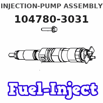
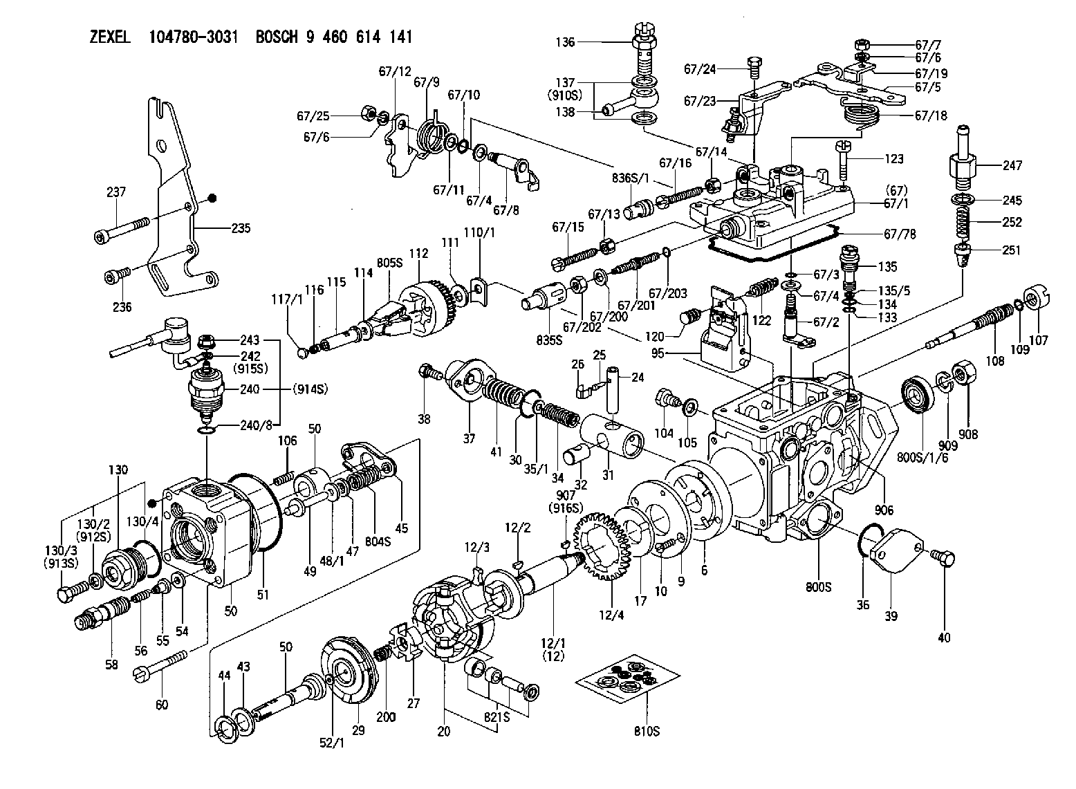
Information injection-pump assembly
BOSCH
9 460 614 141
9460614141
ZEXEL
104780-3031
1047803031
MITSUBISHI-HEAV
32A6500332
32a6500332
Rating:
Compare Prices: .
As an associate, we earn commssions on qualifying purchases through the links below

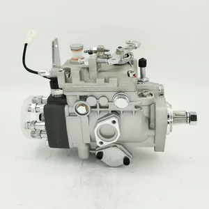
Riginal Fuel Injection Pump Compatible For MITSUBISHI S4S 3.3L 32A65-00332 104780-3031 32A6500332 1047803031 Engine Replacement Parts
SDETASOQ Precise control: precise fuel injection, optimized combustion efficiency, reduced fuel consumption, and improved engine power output || Long lifespan and low maintenance: using high-strength wear-resistant alloy materials and corrosion-resistant coatings to reduce maintenance costs and downtime || Stable operation under all operating conditions: tested in extreme environments, continuously stable, and adaptable to various complex road and climate conditions || Silent and efficient operation: Adopting a noise reduction structure, it can maintain quietness even during high-speed operation, without interfering with the driving experience || Original Fuel Injection Pump Compatible For MITSUBISHI S4S 3.3L 32A65-00332 104780-3031 32A6500332 1047803031 Engine Replacement Parts
SDETASOQ Precise control: precise fuel injection, optimized combustion efficiency, reduced fuel consumption, and improved engine power output || Long lifespan and low maintenance: using high-strength wear-resistant alloy materials and corrosion-resistant coatings to reduce maintenance costs and downtime || Stable operation under all operating conditions: tested in extreme environments, continuously stable, and adaptable to various complex road and climate conditions || Silent and efficient operation: Adopting a noise reduction structure, it can maintain quietness even during high-speed operation, without interfering with the driving experience || Original Fuel Injection Pump Compatible For MITSUBISHI S4S 3.3L 32A65-00332 104780-3031 32A6500332 1047803031 Engine Replacement Parts

High Pressure Diesel Fuel Pump 1046803031 104680-3031 32A65-00332 32A6500332 Compatible With S4S Tractor Fuel Injection Pump
YDLLLRGG Made of wear-resistant materials such as high-strength alloys and ceramic seals, with a lifespan of over 200000 kilometers and corrosion-resistant design suitable for harsh working conditions. || Intelligent pressure control combined with engine management system dynamically optimizes fuel injection strategy and adjusts pressure in real-time to match driving needs. || Silent and low vibration noise reduction technology optimizes the internal gear or cam structure, reducing operating noise by 30% and improving driving comfort. || Continuously and steadily output to reduce pressure fluctuations, avoid engine vibration, and extend the lifespan of surrounding components. || The compact and lightweight design reduces the volume by 15% -20% compared to traditional pumps, and is suitable for compact cabin layouts such as hybrid/electric vehicles,The aluminum alloy shell balances strength and lightweight.
YDLLLRGG Made of wear-resistant materials such as high-strength alloys and ceramic seals, with a lifespan of over 200000 kilometers and corrosion-resistant design suitable for harsh working conditions. || Intelligent pressure control combined with engine management system dynamically optimizes fuel injection strategy and adjusts pressure in real-time to match driving needs. || Silent and low vibration noise reduction technology optimizes the internal gear or cam structure, reducing operating noise by 30% and improving driving comfort. || Continuously and steadily output to reduce pressure fluctuations, avoid engine vibration, and extend the lifespan of surrounding components. || The compact and lightweight design reduces the volume by 15% -20% compared to traditional pumps, and is suitable for compact cabin layouts such as hybrid/electric vehicles,The aluminum alloy shell balances strength and lightweight.

Compatible with Mitsubishi Engine S4S 3.3L Fuel Injection Pump 104780-3031 32A65-00332 1047803031
KoovDem Part Number: 104780-3031 32A65-00332 1047803031 Note: Please check the fitment carefully before purchase. Or just tell us the part number you need. || Part Name: Fuel Injection Pump || Engine: 3.3L, powerful and efficient option for various vehicles. Known for reliability and durability, delivering strong performance and smooth operation. Popular choice for daily commuting or tough terrain, providing necessary power and efficiency. Versatile design seamlessly integrates into a wide range of vehicles for optimal performance and driving experience. || Suitable for use with the Mitsubishi Engine S4S 3.3L. || Package included: One unit of Fuel Injection Pump with the part number 104780-3031, also known as 32A65-00332. This high-quality pump is designed to efficiently deliver fuel to your engine, ensuring optimal performance and fuel efficiency. Trust in this reliable pump to keep your vehicle running smoothly and effectively.
KoovDem Part Number: 104780-3031 32A65-00332 1047803031 Note: Please check the fitment carefully before purchase. Or just tell us the part number you need. || Part Name: Fuel Injection Pump || Engine: 3.3L, powerful and efficient option for various vehicles. Known for reliability and durability, delivering strong performance and smooth operation. Popular choice for daily commuting or tough terrain, providing necessary power and efficiency. Versatile design seamlessly integrates into a wide range of vehicles for optimal performance and driving experience. || Suitable for use with the Mitsubishi Engine S4S 3.3L. || Package included: One unit of Fuel Injection Pump with the part number 104780-3031, also known as 32A65-00332. This high-quality pump is designed to efficiently deliver fuel to your engine, ensuring optimal performance and fuel efficiency. Trust in this reliable pump to keep your vehicle running smoothly and effectively.
You can express buy:
USD 393.69
13-05-2025
13-05-2025
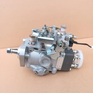
VE Pump Diesel Fuel Injection Pump 1046803031 104680-3031 32A65-00332 32A6500332 For S4S Tractor Fuel Injection Pump
USD 408.01
13-05-2025
13-05-2025
Diesel fuel injection pump 104680-3031 NP-VE4/10F1100RNP2434 32A65-00332 For Mitsubishi S4q2 S4scav S4stc
USD 393.69
13-05-2025
13-05-2025
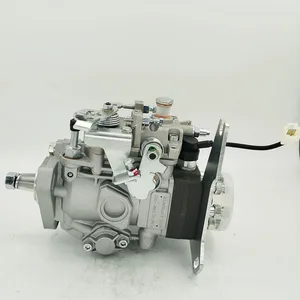
High Pressure Diesel Fuel Pump 1046803031 104680-3031 32A65-00332 32A6500332 For S4S Tractor Fuel Injection Pump
Images:
USD 416.9

[14-Jun-2025]
USD 416.9
[14-Jun-2025]
USD 489.65

[08-Jun-2025]
Components :
| 0. | INJECTION-PUMP ASSEMBLY | 104780-3031 |
| 1. | _ | |
| 2. | FUEL INJECTION PUMP | 104680-3031 |
| 3. | NUMBER PLATE | 146989-3300 |
| 4. | _ | |
| 5. | CAPSULE | |
| 6. | ADJUSTING DEVICE | |
| 7. | NOZZLE AND HOLDER ASSY | |
| 8. | Nozzle and Holder | |
| 9. | Open Pre:MPa(Kqf/cm2) | |
| 10. | NOZZLE-HOLDER | |
| 11. | NOZZLE |
Scheme ###:
| 1/6. | [1] | 146601-0900 | PACKING RING |
| 6. | [1] | 146100-0420 | SUPPLY PUMP |
| 9. | [1] | 146103-0100 | COVER |
| 10. | [2] | 139104-0000 | FLAT-HEAD SCREW |
| 12. | [1] | 146200-0020 | DRIVE SHAFT |
| 12/1. | [1] | 146200-0000 | DRIVE SHAFT |
| 12/2. | [1] | 146201-0000 | WOODRUFF KEY |
| 12/3. | [2] | 146202-0100 | DAMPER |
| 12/4. | [1] | 146203-0000 | TOOTHED GEAR |
| 17. | [1] | 146204-0000 | PLAIN WASHER |
| 20. | [1] | 146210-2320 | ROLLER SET |
| 24. | [1] | 146303-0000 | BEARING PIN |
| 25. | [1] | 146304-0000 | BEARING PIN |
| 26. | [1] | 146305-0000 | CLAMPING BAND |
| 27. | [1] | 146205-0000 | SLOTTED WASHER |
| 29. | [1] | 146220-4820 | CAM PLATE |
| 30. | [1] | 146600-0800 | O-RING |
| 31. | [1] | 146311-5420 | PUMP PLUNGER |
| 32. | [1] | 146301-0000 | SLIDING PIECE |
| 34. | [1] | 146312-6300 | COMPRESSION SPRING |
| 34B. | [1] | 146312-6200 | COMPRESSION SPRING |
| 35/1. | [1] | 146690-3200 | SHIM D11.5&9.4T0.1 |
| 35/1. | [1] | 146690-3300 | SHIM D11.5&9.4T0.2 |
| 35/1. | [1] | 146690-3400 | SHIM D11.5&9.4T0.25 |
| 35/1. | [1] | 146690-3500 | SHIM D11.5&9.4T1.0 |
| 35/1. | [1] | 146690-4100 | SHIM D11.5&9.4T2 |
| 35/1. | [1] | 146690-4200 | SHIM D11.5&9.4T0.5 |
| 35/1. | [1] | 146690-4300 | SHIM D11.5&9.4T0.75 |
| 36. | [1] | 146600-0800 | O-RING |
| 37. | [1] | 146310-4020 | COVER |
| 38. | [2] | 146620-5000 | BLEEDER SCREW |
| 39. | [1] | 146310-0100 | COVER |
| 40. | [2] | 146620-5000 | BLEEDER SCREW |
| 41. | [1] | 146312-1900 | COMPRESSION SPRING |
| 43. | [1] | 146230-0000 | SHIM |
| 44. | [1] | 146230-0100 | PLAIN WASHER |
| 45. | [1] | 146231-0001 | SLOTTED WASHER |
| 47. | [2] | 146233-0000 | SLOTTED WASHER |
| 48/1. | [1] | 146603-0000 | SHIM D17.0&5.2T0.50 |
| 48/1. | [1] | 146603-0100 | SHIM D17.0&5.2T0.80 |
| 48/1. | [1] | 146603-0200 | SHIM D17.0&5.2T1.00 |
| 48/1. | [1] | 146603-0300 | SHIM D17.0&5.2T1.20 |
| 48/1. | [1] | 146603-0400 | SHIM D17.0&5.2T1.50 |
| 48/1. | [1] | 146603-0500 | SHIM D17.0&5.2T1.80 |
| 48/1. | [1] | 146603-0600 | SHIM D17.0&5.2T2.00 |
| 48/1. | [1] | 146690-1400 | SHIM D17&5.2T0.9 |
| 48/1. | [1] | 146690-1500 | SHIM D17&5.2T1.1 |
| 48/1. | [1] | 146690-1600 | SHIM D17&5.2T1.3 |
| 48/1. | [1] | 146690-1700 | SHIM D17&5.2T1.4 |
| 48/1. | [1] | 146690-1800 | SHIM D17&5.2T1.6 |
| 48/1. | [1] | 146690-1900 | SHIM D17&5.2T1.7 |
| 48/1. | [1] | 146690-5800 | SHIM D17&5.2T2.1 |
| 48/1. | [1] | 146690-5900 | SHIM D17&5.2T2.2 |
| 48/1. | [1] | 146690-6000 | SHIM D17&5.2T2.3 |
| 48/1. | [1] | 146690-6100 | SHIM D17&5.2T2.4 |
| 48/1. | [1] | 146690-6200 | SHIM D17&5.2T2.5 |
| 48/1. | [1] | 146690-6300 | SHIM D17&5.2T2.6 |
| 48/1. | [1] | 146690-6400 | SHIM D17&5.2T2.7 |
| 48/1. | [1] | 146690-6500 | SHIM D17&5.2T2.8 |
| 48/1. | [1] | 146690-6600 | SHIM D17&5.2T2.9 |
| 48/1. | [1] | 146690-6700 | SHIM D17&5.2T3.0 |
| 48/1. | [1] | 146690-6800 | SHIM D17&5.2T3.1 |
| 48/1. | [1] | 146690-6900 | SHIM D17&5.2T3.2 |
| 48/1. | [1] | 146690-7000 | SHIM D17&5.2T3.3 |
| 48/1. | [1] | 146690-7100 | SHIM D17&5.2T3.4 |
| 48/1. | [1] | 146690-7200 | SHIM D17&5.2T0.4 |
| 48/1. | [1] | 146690-7300 | SHIM D17&5.2T0.6 |
| 48/1. | [1] | 146690-7400 | SHIM D17&5.2T0.7 |
| 48/1. | [1] | 146690-7500 | SHIM D17&5.2T1.9 |
| 48/1. | [1] | 146690-7800 | SHIM D17&5.2T0.2 |
| 49. | [2] | 146234-0600 | GUIDE PIN |
| 50. | [1] | 146403-9520 | HYDRAULIC HEAD |
| 50. | [1] | 146403-9520 | HYDRAULIC HEAD |
| 50. | [1] | 146403-9520 | HYDRAULIC HEAD |
| 51. | [1] | 146600-0000 | O-RING |
| 52/1. | [1] | 146420-0000 | SHIM D9.5&3.0T1.90 |
| 52/1. | [1] | 146420-0100 | SHIM D9.5&3.0T1.92 |
| 52/1. | [1] | 146420-0200 | SHIM D9.5&3.0T1.94 |
| 52/1. | [1] | 146420-0300 | SHIM D9.5&3.0T1.96 |
| 52/1. | [1] | 146420-0400 | SHIM D9.5&3.0T1.98 |
| 52/1. | [1] | 146420-0500 | SHIM D9.5&3.0T2.00 |
| 52/1. | [1] | 146420-0600 | SHIM D9.5&3.0T2.02 |
| 52/1. | [1] | 146420-0700 | SHIM D9.5&3.0T2.04 |
| 52/1. | [1] | 146420-0800 | SHIM D9.5&3.0T2.06 |
| 52/1. | [1] | 146420-0900 | SHIM D9.5&3.0T2.08 |
| 52/1. | [1] | 146420-1000 | SHIM D9.5&3.0T2.10 |
| 52/1. | [1] | 146420-1100 | SHIM D9.5&3.0T2.12 |
| 52/1. | [1] | 146420-1200 | SHIM D9.5&3.0T2.14 |
| 52/1. | [1] | 146420-1300 | SHIM D9.5&3.0T2.16 |
| 52/1. | [1] | 146420-1400 | SHIM D9.5&3.0T2.18 |
| 52/1. | [1] | 146420-1500 | SHIM D9.5&3.0T2.20 |
| 52/1. | [1] | 146420-1600 | SHIM D9.5&3.0T2.22 |
| 52/1. | [1] | 146420-1700 | SHIM D9.5&3.0T2.24 |
| 52/1. | [1] | 146420-1800 | SHIM D9.5&3.0T2.26 |
| 52/1. | [1] | 146420-1900 | SHIM D9.5&3.0T2.28 |
| 52/1. | [1] | 146420-2000 | SHIM D9.5&3.0T2.30 |
| 52/1. | [1] | 146420-2100 | SHIM D9.5&3.0T2.32 |
| 52/1. | [1] | 146420-2200 | SHIM D9.5&3.0T2.34 |
| 52/1. | [1] | 146420-2300 | SHIM D9.5&3.0T2.36 |
| 52/1. | [1] | 146420-2400 | SHIM D9.5&3.0T2.38 |
| 52/1. | [1] | 146420-2500 | SHIM D9.5&3.0T2.40 |
| 52/1. | [1] | 146420-2600 | SHIM D9.5&3.0T2.42 |
| 52/1. | [1] | 146420-2700 | SHIM D9.5&3.0T2.44 |
| 52/1. | [1] | 146420-2800 | SHIM D9.5&3.0T2.46 |
| 52/1. | [1] | 146420-2900 | SHIM D9.5&3.0T2.48 |
| 52/1. | [1] | 146420-3000 | SHIM D9.5&3.0T2.50 |
| 52/1. | [1] | 146420-3100 | SHIM D9.5&3.0T2.52 |
| 52/1. | [1] | 146420-3200 | SHIM D9.5&3.0T2.54 |
| 52/1. | [1] | 146420-3300 | SHIM D9.5&3.0T2.56 |
| 52/1. | [1] | 146420-3400 | SHIM D9.5&3.0T2.58 |
| 52/1. | [1] | 146420-3500 | SHIM D9.5&3.0T2.60 |
| 52/1. | [1] | 146420-3600 | SHIM D9.5&3.0T2.62 |
| 52/1. | [1] | 146420-3700 | SHIM D9.5&3.0T2.64 |
| 52/1. | [1] | 146420-3800 | SHIM D9.5&3.0T2.66 |
| 52/1. | [1] | 146420-3900 | SHIM D9.5&3.0T2.68 |
| 52/1. | [1] | 146420-4000 | SHIM D9.5&3.0T2.70 |
| 52/1. | [1] | 146420-4100 | SHIM D9.5&3.0T2.72 |
| 52/1. | [1] | 146420-4200 | SHIM D9.5&3.0T2.74 |
| 52/1. | [1] | 146420-4300 | SHIM D9.5&3.0T2.76 |
| 52/1. | [1] | 146420-4400 | SHIM D9.5&3.0T2.78 |
| 52/1. | [1] | 146420-4500 | SHIM D9.5&3.0T2.80 |
| 52/1. | [1] | 146420-4600 | SHIM D9.5&3.0T2.82 |
| 52/1. | [1] | 146420-4700 | SHIM D9.5&3.0T2.84 |
| 52/1. | [1] | 146420-4800 | SHIM D9.5&3.0T2.86 |
| 52/1. | [1] | 146420-4900 | SHIM D9.5&3.0T2.88 |
| 52/1. | [1] | 146420-5000 | SHIM D9.5&3.0T2.90 |
| 52/1. | [1] | 146420-5100 | SHIM D9.5&3.0T1.74 |
| 52/1. | [1] | 146420-5200 | SHIM D9.5&3.0T1.76 |
| 52/1. | [1] | 146420-5300 | SHIM D9.5&3.0T1.78 |
| 52/1. | [1] | 146420-5400 | SHIM D9.5&3.0T1.80 |
| 52/1. | [1] | 146420-5500 | SHIM D9.5&3.0T1.82 |
| 52/1. | [1] | 146420-5600 | SHIM D9.5&3.0T1.84 |
| 52/1. | [1] | 146420-5700 | SHIM D9.5&3.0T1.86 |
| 52/1. | [1] | 146420-5800 | SHIM D9.5&3.0T1.88 |
| 54. | [4] | 146433-0100 | GASKET D12&6.4T1.00 |
| 55. | [4] | 146430-0320 | DELIVERY-VALVE ASSEMBLY |
| 56. | [4] | 146432-0000 | COMPRESSION SPRING |
| 58. | [4] | 146440-0220 | FITTING |
| 60. | [3] | 139106-0100 | FLAT-HEAD SCREW |
| 67. | [1] | 146822-0120 | GOVERNOR COVER |
| 67/1. | [1] | 146508-1022 | GOVERNOR COVER |
| 67/2. | [1] | 146515-2520 | CONTROL SHAFT |
| 67/3. | [1] | 146600-0100 | O-RING |
| 67/4. | [2] | 139310-0200 | PLAIN WASHER |
| 67/4. | [2] | 139310-0200 | PLAIN WASHER |
| 67/5. | [1] | 146832-5500 | CONTROL LEVER MARK:255 |
| 67/5B. | [1] | 146832-5600 | CONTROL LEVER MARK:256 |
| 67/5C. | [1] | 146832-9300 | CONTROL LEVER MARK:293 |
| 67/5D. | [1] | 146832-9400 | CONTROL LEVER MARK:294 |
| 67/6. | [2] | 014110-6440 | LOCKING WASHER |
| 67/6. | [2] | 014110-6440 | LOCKING WASHER |
| 67/7. | [1] | 013020-6040 | UNION NUT M6P1H5 |
| 67/8. | [1] | 146515-1820 | LEVER SHAFT |
| 67/9. | [1] | 146587-4500 | COILED SPRING |
| 67/10. | [1] | 146600-0200 | O-RING |
| 67/11. | [1] | 146602-0100 | PLAIN WASHER D14&10.1T1.50 |
| 67/12. | [1] | 146540-1300 | CONTROL LEVER |
| 67/12B. | [1] | 146540-1400 | CONTROL LEVER MARK:0 |
| 67/12C. | [1] | 146540-5200 | CONTROL LEVER |
| 67/12D. | [1] | 146540-5300 | CONTROL LEVER |
| 67/13. | [1] | 146621-1700 | UNION NUT |
| 67/14. | [1] | 146621-1700 | UNION NUT |
| 67/15. | [1] | 146526-2800 | BLEEDER SCREW |
| 67/16. | [1] | 146526-3400 | BLEEDER SCREW |
| 67/18. | [1] | 146587-0400 | COILED SPRING |
| 67/19. | [1] | 146541-0000 | ANGLE PIECE |
| 67/23. | [1] | 146925-2520 | BRACKET |
| 67/24. | [2] | 139006-4500 | BLEEDER SCREW |
| 67/25. | [1] | 013020-6040 | UNION NUT M6P1H5 |
| 67/78. | [1] | 146600-4400 | SEAL RING |
| 67/200. | [1] | 139308-0300 | PLAIN WASHER |
| 67/201. | [1] | 146545-3400 | THREADED PIN L53.00 |
| 67/201B. | [1] | 146545-3500 | THREADED PIN L55.00 |
| 67/201C. | [1] | 146545-3600 | THREADED PIN L57.00 |
| 67/202. | [1] | 139208-0900 | UNION NUT |
| 67/203. | [1] | 146600-1200 | O-RING |
| 95. | [1] | 146871-7220 | FULCRUM LEVER |
| 104. | [2] | 146568-0000 | SLOTTED SPRING PIN |
| 105. | [2] | 026508-1140 | GASKET D11.4&8.2T1 |
| 106. | [2] | 146588-0500 | COILED SPRING |
| 107. | [1] | 146569-0300 | UNION NUT |
| 108. | [1] | 146570-0420 | GOVERNOR SHAFT |
| 109. | [1] | 146600-0400 | O-RING |
| 110/1. | [1] | 146571-0000 | SHIM D20.2&8.3T1.05 |
| 110/1. | [1] | 146571-0100 | SHIM D20.2&8.3T1.25 |
| 110/1. | [1] | 146571-0200 | SHIM D20.2&8.3T1.45 |
| 110/1. | [1] | 146571-0300 | SHIM D20.2&8.3T1.65 |
| 110/1. | [1] | 146571-0400 | SHIM D20.2&8.3T1.85 |
| 110/1. | [1] | 146571-0500 | SHIM D20.2&8.3T1.15 |
| 110/1. | [1] | 146571-0600 | SHIM D20.2&8.3T1.35 |
| 110/1. | [1] | 146571-0700 | SHIM D20.2&8.3T1.55 |
| 110/1. | [1] | 146571-0800 | SHIM D20.2&8.3T1.75 |
| 111. | [1] | 146602-0600 | PLAIN WASHER D20&8.4T1.40 |
| 112. | [1] | 146572-0020 | FLYWEIGHT ASSEMBLY |
| 114. | [1] | 146602-2600 | PLAIN WASHER D34&13T1.0 |
| 115. | [1] | 146976-1200 | SLIDING SLEEVE |
| 116. | [1] | 146576-0200 | CAP |
| 117/1. | [1] | 146577-1800 | PLUG L2.10 |
| 117/1. | [1] | 146577-1900 | PLUG L2.30 |
| 117/1. | [1] | 146577-2000 | PLUG L2.50 |
| 117/1. | [1] | 146577-2100 | PLUG L2.70 |
| 117/1. | [1] | 146577-2200 | PLUG L2.90 |
| 117/1. | [1] | 146577-2300 | PLUG L3.10 |
| 117/1. | [1] | 146577-2400 | PLUG L3.30 |
| 117/1. | [1] | 146577-2500 | PLUG L3.50 |
| 117/1. | [1] | 146577-2600 | PLUG L3.70 |
| 117/1. | [1] | 146577-2700 | PLUG L3.90 |
| 117/1. | [1] | 146577-2800 | PLUG L4.10 |
| 117/1. | [1] | 146577-2900 | PLUG L4.30 |
| 117/1. | [1] | 146577-3000 | PLUG L4.50 |
| 117/1. | [1] | 146577-3100 | PLUG L4.70 |
| 117/1. | [1] | 146577-3200 | PLUG L4.90 |
| 117/1. | [1] | 146577-3300 | PLUG L5.10 |
| 117/1. | [1] | 146577-6700 | PLUG L2.2 |
| 117/1. | [1] | 146577-6800 | PLUG L2.4 |
| 117/1. | [1] | 146577-6900 | PLUG L2.6 |
| 117/1. | [1] | 146577-7000 | PLUG L2.8 |
| 117/1. | [1] | 146577-7100 | PLUG L3.0 |
| 117/1. | [1] | 146577-7200 | PLUG L3.2 |
| 117/1. | [1] | 146577-7300 | PLUG L3.4 |
| 117/1. | [1] | 146577-7400 | PLUG L3.6 |
| 117/1. | [1] | 146577-7500 | PLUG L3.8 |
| 117/1. | [1] | 146577-7600 | PLUG L4.0 |
| 117/1. | [1] | 146577-7700 | PLUG L4.2 |
| 117/1. | [1] | 146577-7800 | PLUG L4.4 |
| 117/1. | [1] | 146577-7900 | PLUG L4.6 |
| 117/1. | [1] | 146577-8000 | PLUG L4.8 |
| 117/1. | [1] | 146577-8100 | PLUG L5.0 |
| 117/1. | [1] | 146877-0000 | PLUG L5.2 |
| 117/1. | [1] | 146877-0100 | PLUG L5.3 |
| 117/1. | [1] | 146877-0200 | PLUG L5.4 |
| 117/1. | [1] | 146877-0300 | PLUG L5.5 |
| 117/1. | [1] | 146877-4700 | PLUG |
| 117/1. | [1] | 146877-4800 | PLUG |
| 117/1. | [1] | 146877-4900 | PLUG |
| 117/1. | [1] | 146877-5000 | PLUG |
| 120. | [1] | 146879-3320 | RETAINING PIN |
| 122. | [1] | 146580-3700 | GOVERNOR SPRING |
| 123. | [4] | 139106-0200 | FLAT-HEAD SCREW |
| 130. | [1] | 146421-0020 | CAPSULE |
| 130/2. | [1] | 026508-1140 | GASKET D11.4&8.2T1 |
| 130/3. | [1] | 146422-0000 | BLEEDER SCREW |
| 130/4. | [1] | 146600-0500 | O-RING |
| 133. | [1] | 146600-0600 | O-RING |
| 134. | [1] | 146600-0700 | O-RING |
| 135. | [1] | 146110-0220 | CONTROL VALVE |
| 135/5. | [1] | 146114-0000 | SPRING WASHER |
| 136. | [1] | 146120-0120 | OVER FLOW VALVE |
| 137. | [2] | 139512-0500 | GASKET |
| 138. | [1] | 146610-3120 | INLET UNION |
| 200. | [1] | 146206-0100 | COILED SPRING |
| 235. | [1] | 146935-8601 | BRACKET |
| 236. | [2] | 010206-2240 | HEX-SOCKET-HEAD CAP SCREW |
| 237. | [1] | 146620-0200 | HEX-SOCKET-HEAD CAP SCREW |
| 240. | [1] | 146650-1220 | PULLING ELECTROMAGNET |
| 240/8. | [1] | 146600-1700 | O-RING |
| 242. | [1] | 146662-1420 | WIRE |
| 243. | [1] | 146621-4901 | UNION NUT |
| 245. | [1] | 139512-0500 | GASKET |
| 247. | [1] | 146669-1720 | INLET UNION |
| 251. | [1] | 146125-0101 | FILTER |
| 252. | [1] | 146125-0200 | COILED SPRING |
| 800S. | [1] | 146020-1820 | PUMP HOUSING |
| 800S/1/6. | [1] | 146601-0900 | PACKING RING |
| 804S. | [1] | 146232-0720 | COMPRESSION SPRING |
| 805S. | [1] | 146574-0320 | PARTS SET |
| 810S. | [1] | 146600-1120 | REPAIR SET |
| 821S. | [1] | 146210-5720 | ROLLER SET |
| 835S. | [1] | 146598-1000 | CAP |
| 836S/1. | [1] | 146598-0600 | CAP L18 |
| 836S/1. | [1] | 146598-0700 | CAP L21 |
| 836S/1. | [1] | 146598-0800 | CAP L24 |
| 836S/1. | [1] | 146598-0900 | CAP L27 |
| 906. | [1] | 146989-3300 | NAMEPLATE |
| 907. | [1] | 025803-1640 | WOODRUFF KEY |
| 908. | [1] | 013021-2140 | UNION NUT M12P1.75H10 |
| 909. | [1] | 014111-2440 | LOCKING WASHER D21.5&12.2T3 |
| 910S. | [1] | 146600-6020 | PARTS SET |
| 912S. | [1] | 026508-1140 | GASKET D11.4&8.2T1 |
| 913S. | [1] | 146422-0000 | BLEEDER SCREW |
| 914S. | [1] | 146699-0020 | VALVE SET |
| 915S. | [1] | 146662-1420 | WIRE |
| 916S. | [1] | 025803-1640 | WOODRUFF KEY |
Include in #2:
104780-3031
as INJECTION-PUMP ASSEMBLY
Cross reference number
BOSCH
9 460 614 141
9460614141
ZEXEL
104780-3031
1047803031
MITSUBISHI-HEAV
32A6500332
32a6500332
Zexel num
Bosch num
Firm num
Name
9 460 614 141
32A6500332 MITSUBISHI-HEAV
INJECTION-PUMP ASSEMBLY
S4S * K 11CJ INJECTION PUMP ASSY VE4 VE
S4S * K 11CJ INJECTION PUMP ASSY VE4 VE
Calibration Data:
Adjustment conditions
Test oil
1404 Test oil ISO4113orSAEJ967d
1404 Test oil ISO4113orSAEJ967d
Test oil temperature
degC
45
45
50
Nozzle
105780-0060
Bosch type code
NP-DN0SD1510
Nozzle holder
105780-2150
Opening pressure
MPa
13
13
13.3
Opening pressure
kgf/cm2
133
133
136
Injection pipe
157805-7320
Injection pipe
Inside diameter - outside diameter - length (mm) mm 2-6-450
Inside diameter - outside diameter - length (mm) mm 2-6-450
Joint assembly
157641-4720
Tube assembly
157641-4020
Transfer pump pressure
kPa
20
20
20
Transfer pump pressure
kgf/cm2
0.2
0.2
0.2
Direction of rotation (viewed from drive side)
Right R
Right R
Injection timing adjustment
Pump speed
r/min
1000
1000
1000
Average injection quantity
mm3/st.
46.7
46.2
47.2
Difference in delivery
mm3/st.
4
Basic
*
Oil temperature
degC
50
48
52
Injection timing adjustment_02
Pump speed
r/min
400
400
400
Average injection quantity
mm3/st.
42.2
38.2
46.2
Oil temperature
degC
48
46
50
Injection timing adjustment_03
Pump speed
r/min
600
600
600
Average injection quantity
mm3/st.
44.2
40.2
48.2
Oil temperature
degC
50
48
52
Injection timing adjustment_04
Pump speed
r/min
1000
1000
1000
Average injection quantity
mm3/st.
46.7
45.7
47.7
Difference in delivery
mm3/st.
4.5
Basic
*
Oil temperature
degC
50
48
52
Injection timing adjustment_05
Pump speed
r/min
1100
1100
1100
Average injection quantity
mm3/st.
45.3
35.3
48.8
Oil temperature
degC
50
48
52
Injection quantity adjustment
Pump speed
r/min
1225
1225
1225
Average injection quantity
mm3/st.
9
7
11
Difference in delivery
mm3/st.
3
Basic
*
Oil temperature
degC
50
48
52
Injection quantity adjustment_02
Pump speed
r/min
1350
1350
1350
Average injection quantity
mm3/st.
3
Oil temperature
degC
50
48
52
Injection quantity adjustment_03
Pump speed
r/min
1225
1225
1225
Average injection quantity
mm3/st.
9
5.5
12.5
Difference in delivery
mm3/st.
3.5
Basic
*
Oil temperature
degC
50
48
52
Governor adjustment
Pump speed
r/min
380
380
380
Average injection quantity
mm3/st.
11.8
9.8
13.8
Difference in delivery
mm3/st.
2
Basic
*
Oil temperature
degC
48
46
50
Governor adjustment_02
Pump speed
r/min
275
275
275
Average injection quantity
mm3/st.
35
35
Oil temperature
degC
48
46
50
Governor adjustment_03
Pump speed
r/min
380
380
380
Average injection quantity
mm3/st.
11.8
9.3
14.3
Difference in delivery
mm3/st.
2.5
Basic
*
Oil temperature
degC
48
46
50
Timer adjustment
Pump speed
r/min
100
100
100
Average injection quantity
mm3/st.
56.1
51.1
61.1
Basic
*
Oil temperature
degC
48
46
50
Remarks
Full
Full
Timer adjustment_02
Pump speed
r/min
100
100
100
Average injection quantity
mm3/st.
56.1
51.1
61.1
Oil temperature
degC
48
46
50
Remarks
Full
Full
Speed control lever angle
Pump speed
r/min
380
380
380
Average injection quantity
mm3/st.
0
0
0
Oil temperature
degC
48
46
50
Remarks
Magnet OFF at idling position
Magnet OFF at idling position
0000000901
Pump speed
r/min
800
800
800
Overflow quantity
cm3/min
420
290
550
Oil temperature
degC
50
48
52
Stop lever angle
Pump speed
r/min
800
800
800
Pressure
kPa
545
516
574
Pressure
kgf/cm2
5.6
5.3
5.9
Basic
*
Oil temperature
degC
50
48
52
Stop lever angle_02
Pump speed
r/min
600
600
600
Pressure
kPa
496
447
545
Pressure
kgf/cm2
5.1
4.6
5.6
Oil temperature
degC
50
48
52
Stop lever angle_03
Pump speed
r/min
700
700
700
Pressure
kPa
520
471
569
Pressure
kgf/cm2
5.3
4.8
5.8
Oil temperature
degC
50
48
52
Stop lever angle_04
Pump speed
r/min
800
800
800
Pressure
kPa
545
506
584
Pressure
kgf/cm2
5.6
5.2
6
Basic
*
Oil temperature
degC
50
48
52
Stop lever angle_05
Pump speed
r/min
900
900
900
Pressure
kPa
567
518
616
Pressure
kgf/cm2
5.8
5.3
6.3
Oil temperature
degC
50
48
52
Stop lever angle_06
Pump speed
r/min
1000
1000
1000
Pressure
kPa
591
542
640
Pressure
kgf/cm2
6
5.5
6.5
Oil temperature
degC
50
48
52
Stop lever angle_07
Pump speed
r/min
1100
1100
1100
Pressure
kPa
621
572
670
Pressure
kgf/cm2
6.3
5.8
6.8
Oil temperature
degC
50
48
52
0000001101
Pump speed
r/min
800
800
800
Timer stroke
mm
2.6
2.4
2.8
Basic
*
Oil temperature
degC
50
48
52
_02
Pump speed
r/min
600
600
600
Timer stroke
mm
1.2
0.6
1.8
Oil temperature
degC
50
48
52
_03
Pump speed
r/min
800
800
800
Timer stroke
mm
2.6
2.2
3
Basic
*
Oil temperature
degC
50
48
52
_04
Pump speed
r/min
1000
1000
1000
Timer stroke
mm
4.1
3.5
4.7
Oil temperature
degC
50
48
52
_05
Pump speed
r/min
1100
1100
1100
Timer stroke
mm
4.1
3.6
4.5
Oil temperature
degC
50
48
52
0000001201
Max. applied voltage
V
8
8
8
Test voltage
V
13
12
14
0000001401
Pump speed
r/min
1000
1000
1000
Average injection quantity
mm3/st.
17
16.5
17.5
Timer stroke TA
mm
3
2.8
3.2
Basic
*
Oil temperature
degC
50
48
52
_02
Pump speed
r/min
1100
1100
1100
Average injection quantity
mm3/st.
22
21
23
Timer stroke TA
mm
4.1
3.6
4.5
Timer stroke variation dT
mm
0
0
0
Oil temperature
degC
50
48
52
_03
Pump speed
r/min
1100
1100
1100
Average injection quantity
mm3/st.
14
13
15
Timer stroke TA
mm
2.5
1.5
3.5
Timer stroke variation dT
mm
3.6
3.6
3.6
Oil temperature
degC
50
48
52
Timing setting
K dimension
mm
3.3
3.2
3.4
KF dimension
mm
5.8
5.7
5.9
MS dimension
mm
2.5
2.4
2.6
Control lever angle alpha
deg.
25
21
29
Control lever angle beta
deg.
24
19
29
Test data Ex:
0000001801 STARTING I/Q ADJUSTMENT
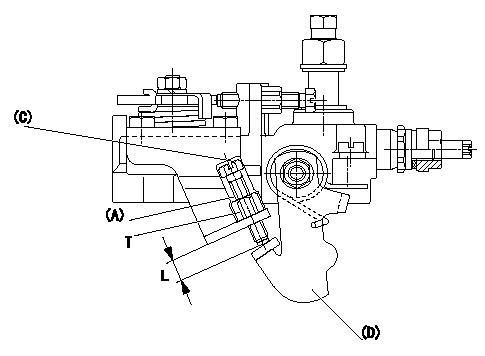
Starting Q decrease lever adjustment
Adjust using the screw (A) so that the standards are satisfied, then fix using the nut (B).
Screw (B) protrusion: L
(C) = Cap
(D) = Stop lever
----------
L=7.4~11.1mm
----------
L=7.4~11.1mm T=6~9N-m(0.6~0.9kgf-m)
----------
L=7.4~11.1mm
----------
L=7.4~11.1mm T=6~9N-m(0.6~0.9kgf-m)
Information:
Start By:a. remove valve covers
Typical Example1. Use Tool (A) to loosen the nuts and remove fuel lines (2).2. Disconnect fuel lines (1) from the valve cover base adapters.
Put protection caps (5F-2807) and plugs (2F-2990) on the fuel line openings to keep dirt and foreign material out of the fuel system.
3. Remove locks (3) and fuel line adapters (4) from the valve cover bases for clearance to remove the rocker shaft bolts. 4. Remove bolts (5) and rocker shaft assemblies (6) from the cylinder head. 5. Remove push rods (7) from the cylinder heads.6. Put identification on each valve bridge as to its location. Remove valve bridges (8) from the cylinder heads.Install Rocker Shaft Assemblies
1. Put clean engine oil on the bridge dowels, push rods (2) and inside bridges (1). Install bridges (1) and push rods (2) in the correct positions. 2. Push straight down on the top contact surface of valve bridge (1) with a force of 4 to 45 N (1 to 10 lb). Turn the adjustment screw clockwise until contact is made with the valve stem. Turn the adjustment screw 20 to 30 degrees more to keep bridge (1) straight on the dowel. Hold the adjustment screw in this position and tighten the locknut to a torque of 28 4 N m (22 3 lb ft). 3. Put rocker shaft assembly (3) in position on the cylinder head. Make sure the adjustment screws in the rocker arms are correctly engaged with the push rods. 4. Put clean engine oil on the threads of the bolts and install the bolts to hold rocker shaft assembly. Tighten the bolts as follows:a. Tighten bolts 1 through 6 in number sequence shown to a torque of 270 25 N m (200 20 lb ft).b. Tighten bolts 1 through 6 in number sequence shown to a torque of 447 20 N m (330 15 lb ft).c. Tighten bolts 1 through 6 in number sequence shown again to a torque of 447 20 N m (330 15 lb ft). 5. Put clean engine oil on the O-ring seals and install fuel line adapters (5), the washers, spaces, locks and nuts (4). Tighten nuts (4) to a torque of 14 3 N m (10 2 lb ft) 6. Install fuel lines (7) and connect fuel lines (6) to the fuel line adapters. Use Tool (A) and tighten the nuts for fuel lines (7). Tighten all fuel line nuts to a torque of 40 7 N m (30 5 lb ft).7. Make an adjustment of the valves to have a clearance of 0.38 mm (.015 in) for intake and 0.76 mm (.030 in) for exhaust. See Valve Clearance Setting in Testing And Adjusting.End By:a. install valve covers Disassemble Rocker Shaft Assemblies
Start By:a. remove rocker shaft assemblies 1. Remove retainer (1) from the end of the shaft.2. Remove the washers and rocker arm (2). 3. Use Tool (A) to remove the pin that