Information injection-pump assembly
BOSCH
F 01G 09W 0BH
f01g09w0bh
ZEXEL
104769-2191
1047692191
Rating:
Cross reference number
BOSCH
F 01G 09W 0BH
f01g09w0bh
ZEXEL
104769-2191
1047692191
Zexel num
Bosch num
Firm num
Name
Calibration Data:
Adjustment conditions
Test oil
1404 Test oil ISO4113orSAEJ967d
1404 Test oil ISO4113orSAEJ967d
Test oil temperature
degC
45
45
50
Nozzle
105780-0060
Bosch type code
NP-DN0SD1510
Nozzle holder
105780-2150
Opening pressure
MPa
13
13
13.3
Opening pressure
kgf/cm2
133
133
136
Injection pipe
157805-7320
Injection pipe
Inside diameter - outside diameter - length (mm) mm 2-6-450
Inside diameter - outside diameter - length (mm) mm 2-6-450
Joint assembly
157641-4720
Tube assembly
157641-4020
Transfer pump pressure
kPa
20
20
20
Transfer pump pressure
kgf/cm2
0.2
0.2
0.2
Direction of rotation (viewed from drive side)
Right R
Right R
Injection timing adjustment
Pump speed
r/min
600
600
600
Boost pressure
kPa
0
0
0
Boost pressure
mmHg
0
0
0
Average injection quantity
mm3/st.
31.7
31.3
32.1
Difference in delivery
mm3/st.
2
Basic
*
Oil temperature
degC
50
48
52
Remarks
Full
Full
Injection timing adjustment_02
Pump speed
r/min
900
900
900
Boost pressure
kPa
33.3
32
34.6
Boost pressure
mmHg
250
240
260
Average injection quantity
mm3/st.
39
38.6
39.4
Difference in delivery
mm3/st.
2
Basic
*
Oil temperature
degC
50
48
52
Remarks
CBS
CBS
Injection timing adjustment_03
Pump speed
r/min
600
600
600
Boost pressure
kPa
0
0
0
Boost pressure
mmHg
0
0
0
Average injection quantity
mm3/st.
31.7
30.7
32.7
Oil temperature
degC
50
48
52
Injection timing adjustment_04
Pump speed
r/min
900
900
900
Boost pressure
kPa
33.3
32
34.6
Boost pressure
mmHg
250
240
260
Average injection quantity
mm3/st.
39
38
40
Difference in delivery
mm3/st.
2.5
Basic
*
Oil temperature
degC
50
48
52
Injection timing adjustment_05
Pump speed
r/min
1200
1200
1200
Boost pressure
kPa
64
62.7
65.3
Boost pressure
mmHg
480
470
490
Average injection quantity
mm3/st.
43.9
41.9
45.9
Oil temperature
degC
50
48
52
Injection timing adjustment_06
Pump speed
r/min
1800
1800
1800
Boost pressure
kPa
64
62.7
65.3
Boost pressure
mmHg
480
470
490
Average injection quantity
mm3/st.
42.8
40.3
45.3
Oil temperature
degC
50
48
52
Injection timing adjustment_07
Pump speed
r/min
2200
2200
2200
Boost pressure
kPa
64
62.7
65.3
Boost pressure
mmHg
480
470
490
Average injection quantity
mm3/st.
42.5
39.5
45.5
Oil temperature
degC
52
50
54
Injection quantity adjustment
Pump speed
r/min
2300
2300
2300
Boost pressure
kPa
64
62.7
65.3
Boost pressure
mmHg
480
470
490
Average injection quantity
mm3/st.
35.8
34.8
36.8
Basic
*
Oil temperature
degC
52
50
54
Injection quantity adjustment_02
Pump speed
r/min
2300
2300
2300
Boost pressure
kPa
64
62.7
65.3
Boost pressure
mmHg
480
470
490
Average injection quantity
mm3/st.
35.8
32.8
38.8
Oil temperature
degC
52
50
54
Injection quantity adjustment_03
Pump speed
r/min
2400
2400
2400
Boost pressure
kPa
64
62.7
65.3
Boost pressure
mmHg
480
470
490
Average injection quantity
mm3/st.
27.4
22.4
32.4
Difference in delivery
mm3/st.
5
Oil temperature
degC
52
50
54
Injection quantity adjustment_04
Pump speed
r/min
2700
2700
2700
Boost pressure
kPa
64
62.7
65.3
Boost pressure
mmHg
480
470
490
Average injection quantity
mm3/st.
3
Oil temperature
degC
55
52
58
Governor adjustment
Pump speed
r/min
350
350
350
Boost pressure
kPa
0
0
0
Boost pressure
mmHg
0
0
0
Average injection quantity
mm3/st.
7.6
6.6
8.6
Difference in delivery
mm3/st.
0.9
Basic
*
Oil temperature
degC
48
46
50
Governor adjustment_02
Pump speed
r/min
350
350
350
Boost pressure
kPa
0
0
0
Boost pressure
mmHg
0
0
0
Average injection quantity
mm3/st.
7.6
5.6
9.6
Difference in delivery
mm3/st.
1.4
Basic
*
Oil temperature
degC
48
46
50
Governor adjustment_03
Pump speed
r/min
500
500
500
Boost pressure
kPa
0
0
0
Boost pressure
mmHg
0
0
0
Average injection quantity
mm3/st.
3
Oil temperature
degC
48
46
50
Boost compensator adjustment
Pump speed
r/min
1200
1200
1200
Boost pressure
kPa
0
0
0
Boost pressure
mmHg
0
0
0
Average injection quantity
mm3/st.
12.8
7.8
17.8
Oil temperature
degC
50
48
52
Lever angle (shim thickness)
mm
8.4
8.4
8.4
Boost compensator adjustment_02
Pump speed
r/min
900
900
900
Boost pressure
kPa
0
0
0
Boost pressure
mmHg
0
0
0
Average injection quantity
mm3/st.
16.2
9.7
22.7
Oil temperature
degC
50
48
52
Lever angle (shim thickness)
mm
8.4
8.4
8.4
Timer adjustment
Pump speed
r/min
100
100
100
Boost pressure
kPa
0
0
0
Boost pressure
mmHg
0
0
0
Average injection quantity
mm3/st.
38
38
Basic
*
Oil temperature
degC
48
46
50
Timer adjustment_02
Pump speed
r/min
100
100
100
Boost pressure
kPa
0
0
0
Boost pressure
mmHg
0
0
0
Average injection quantity
mm3/st.
38
38
Oil temperature
degC
48
46
50
Speed control lever angle
Pump speed
r/min
350
350
350
Boost pressure
kPa
0
0
0
Boost pressure
mmHg
0
0
0
Average injection quantity
mm3/st.
0
0
0
Oil temperature
degC
48
46
50
Remarks
Magnet OFF at idling position
Magnet OFF at idling position
Speed control lever angle_02
Pump speed
r/min
900
900
900
Boost pressure
kPa
46.9
45.6
48.2
Boost pressure
mmHg
352
342
362
Average injection quantity
mm3/st.
0
0
0
Oil temperature
degC
50
48
52
Remarks
Magnet OFF at full-load position
Magnet OFF at full-load position
0000000901
Pump speed
r/min
900
900
900
Boost pressure
kPa
46.9
45.6
48.2
Boost pressure
mmHg
352
342
362
Overflow quantity
cm3/min
390
260
520
Oil temperature
degC
50
48
52
Stop lever angle
Pump speed
r/min
900
900
900
Boost pressure
kPa
46.9
45.6
48.2
Boost pressure
mmHg
352
342
362
Pressure
kPa
373
344
402
Pressure
kgf/cm2
3.8
3.5
4.1
Basic
*
Oil temperature
degC
50
48
52
Stop lever angle_02
Pump speed
r/min
900
900
900
Boost pressure
kPa
46.9
45.6
48.2
Boost pressure
mmHg
352
342
362
Pressure
kPa
372.5
333
412
Pressure
kgf/cm2
3.8
3.4
4.2
Basic
*
Oil temperature
degC
50
48
52
Stop lever angle_03
Pump speed
r/min
1800
1800
1800
Boost pressure
kPa
64
62.7
65.3
Boost pressure
mmHg
480
470
490
Pressure
kPa
578.5
539
618
Pressure
kgf/cm2
5.9
5.5
6.3
Oil temperature
degC
50
48
52
Stop lever angle_04
Pump speed
r/min
2300
2300
2300
Boost pressure
kPa
64
62.7
65.3
Boost pressure
mmHg
480
470
490
Pressure
kPa
706
667
745
Pressure
kgf/cm2
7.2
6.8
7.6
Oil temperature
degC
52
50
54
0000001101
Pump speed
r/min
900
900
900
Boost pressure
kPa
46.9
45.6
48.2
Boost pressure
mmHg
352
342
362
Timer stroke
mm
1.3
1.1
1.5
Basic
*
Oil temperature
degC
50
48
52
_02
Pump speed
r/min
900
900
900
Boost pressure
kPa
46.9
45.6
48.2
Boost pressure
mmHg
352
342
362
Timer stroke
mm
1.3
1
1.6
Basic
*
Oil temperature
degC
50
48
52
_03
Pump speed
r/min
1800
1800
1800
Boost pressure
kPa
64
62.7
65.3
Boost pressure
mmHg
480
470
490
Timer stroke
mm
4.9
4.3
5.5
Oil temperature
degC
50
48
52
_04
Pump speed
r/min
2300
2300
2300
Boost pressure
kPa
64
62.7
65.3
Boost pressure
mmHg
480
470
490
Timer stroke
mm
6.85
6.3
7.4
Oil temperature
degC
52
50
54
_05
Pump speed
r/min
2500
2500
2500
Boost pressure
kPa
64
62.7
65.3
Boost pressure
mmHg
480
470
490
Timer stroke
mm
6.95
6.5
7.4
Oil temperature
degC
55
52
58
0000001201
Max. applied voltage
V
8
8
8
Test voltage
V
13
12
14
Timing setting
K dimension
mm
3.3
3.2
3.4
KF dimension
mm
6.64
6.54
6.74
MS dimension
mm
1.8
1.7
1.9
BCS stroke
mm
3.9
3.8
4
Control lever angle alpha
deg.
23
19
27
Control lever angle beta
deg.
39
34
44
Test data Ex:
0000001801 POTENTIOMETER ADJUSTMENT
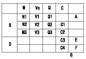
Potentiometer adjustment
1. Applied voltage: Vi
2. Boost pressure = P1kPa {P2 mmHg}
3. Set the control lever at the adjusting point. Position the dummy bolt against the lever and fix.
4. Assemble the potentiometer to obtain output voltage V1 (V) at the fixed position.
5. After mounting the potentiometer, remove the dummy bolt.
A:Adjusting point
B:Performance standards
C:Control lever angle
D:ON, OFF switch standard
E:OFF-->ON
F:OFF-->ON
G:Applied voltage
N:Pump speed
Vo:Output voltage
Q:Injection quantity
C1:Idle
C2:Full speed
----------
V1=4.32+-0.03V Vi=10V P1=0kPa P2=0mmHg
----------
N1=1200r/min N2=-r/min N3=-r/min V1=4.32+-0.03V V2=Measure V V3=Measure V Q1=14+-1cm3/1,000st Q2=-cm3/1,000st Q3=-cm3/1,000st C3=- C4=- G=10V
----------
V1=4.32+-0.03V Vi=10V P1=0kPa P2=0mmHg
----------
N1=1200r/min N2=-r/min N3=-r/min V1=4.32+-0.03V V2=Measure V V3=Measure V Q1=14+-1cm3/1,000st Q2=-cm3/1,000st Q3=-cm3/1,000st C3=- C4=- G=10V
0000001901 M-CSD ADJUSTMENT
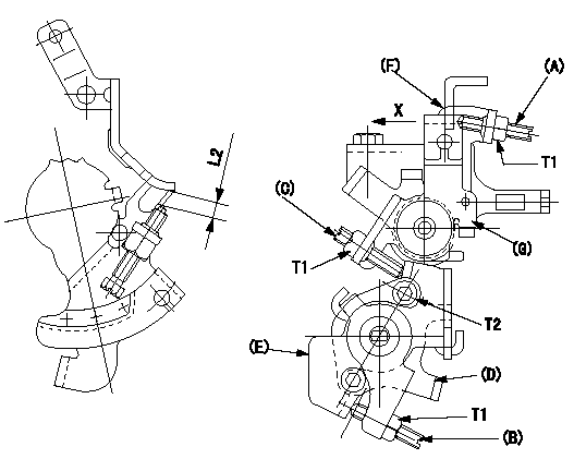
M-CSD adjustment
1. Move the lever E clockwise and when it contacts the stopper D, adjust screw B so that the timer piston advance is a (L1). Then, fix using the nut.
2. With intermediate lever screw (C)'s fixing lever (E) positioned as in 1., pull the intermediate lever in direction X. After confirming that it contacts the stop position, adjust so that screw (C) contacts lever (E) and then fix using the nut.
(In condition (2), intermediate lever: full speed position, at timer advance a.)
Confirm that the timer piston advances to b deg when the intermediate lever is returned.
3. Fast idle adjustment
Pull the intermediate lever in direction x to contact the stopper and adjust the screw (A) so that the gap between the idle set bracket and the idle screw is L2. Fix using the nut.
The gap between the control lever at the idle position and the screw (A) must be L3.
(F) Control lever
(G) Intermediate lever
----------
a=2deg b=0deg L1=1.6mm L2=6+-0.5mm L3=(1.7mm)
----------
T1=6~9N-m(0.6~0.9kgf-m) T2=5~7N-m(0.5~0.7kgf-m) L2=6+-0.5mm
----------
a=2deg b=0deg L1=1.6mm L2=6+-0.5mm L3=(1.7mm)
----------
T1=6~9N-m(0.6~0.9kgf-m) T2=5~7N-m(0.5~0.7kgf-m) L2=6+-0.5mm
0000002001 DASHPOT ADJUSTMENT
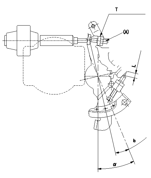
Adjustment of the dash pot
1. Insert a block gauge L (thickness gauge) between the idle set bracket and the idle screw.
2. In the above condition, adjust so that the dashpot adjusting screw (A) contacts the pushrod. Then, fix using the nut.
Record the dashpot return time t.
a = alpha
----------
L=3.8+-0.05mm t=1.8+-0.5sec
----------
T=5~7N-m(0.5~0.7kgf-m) b=7.4deg L=3.8+-0.05mm
----------
L=3.8+-0.05mm t=1.8+-0.5sec
----------
T=5~7N-m(0.5~0.7kgf-m) b=7.4deg L=3.8+-0.05mm
Information:
1. Remove plug (1) from the fuel injection pump housing.2. Use Tool (D) to loosen nut (2) for the fuel injection pump to be removed. Disconnect the fuel injection line nuts, and remove the felt washer. 3. Install Tool (A) in the fuel pump housing as shown with the square end down. Use a small amount of hand force to push down on Tool (A) while the control lever is moved forward to the "FUEL ON" position. Rack travel will stop in the center (zero) position. Hold a light forward force on the governor control lever to keep the fuel racks in the center (zero) position.4. Use Tool (B) to remove bushing (3) from the fuel injection pump housing. 5. Remove bushing (3) and O-ring seal (4).
When injection pumps, spacers and lifters are removed from the injection pump housing, keep the parts of each pump together so they can be installed in their original location.
6. Use Tool (C) to remove fuel injection pump (5). 7. Remove spacer (6) from the fuel injection pump housing. Make a note of the position from which each spacer was removed so each spacer can be installed in its original position.
Be careful when the fuel injection pumps are disassembled. Do not damage the surfaces of the plungers, barrels and bonnets. Any scratches will cause leakage inside the fuel injection pump. The plunger and barrel for each pump are made as a set. Do not put the plunger of one pump in the barrel of another pump. The check assemblies are made as a set. Do not mix the parts of the different check assemblies. Do not remove or make any adjustments of the gear segment on the plunger. It has been preset at the factory. If one part has wear, install a complete new pump assembly. Be careful when the plunger is put into the bore of the barrel.
8. Disassemble the fuel injection pump as follows: Remove ring (7). Separate bonnet (10) from barrel (9). Remove the spring and the check assembly from the bonnet. Remove plunger (8), the washer and spring from barrel (9).Install Fuel Injection Pumps
1. Inspect all parts for wear or damage. The plunger and barrel are serviced only as an assembly. 2. Put clean diesel fuel on plunger (1). Put plunger (1), washer (6) and spring (2) in position on barrel (3).3. Put check valve assembly (7) and spring (8) in bonnet (9). Connect bonnet (9) and barrel (3) together with ring (4). 4. Put spacer (10) into position in the pump housing bore. Be sure the correct spacer is with each pump. 5. Note the location of dowels (11) and (12) in the fuel injection pump housing. These dowels are for alignment of the fuel injection pump. 6. Slot (13) in gear segment (5) must align with dowel (11).7. Groove (14) must engage with dowel (12). 8. Use Tool (A) to put the fuel racks in the center (zero) position. See Remove Fuel Injection Pumps.9. Use Tool