Information injection-pump assembly
BOSCH
9 460 610 383
9460610383
ZEXEL
104769-2171
1047692171
Rating:
Cross reference number
BOSCH
9 460 610 383
9460610383
ZEXEL
104769-2171
1047692171
Zexel num
Bosch num
Firm num
Name
104769-2171
9 460 610 383
INJECTION-PUMP ASSEMBLY
Calibration Data:
Adjustment conditions
Test oil
1404 Test oil ISO4113orSAEJ967d
1404 Test oil ISO4113orSAEJ967d
Test oil temperature
degC
45
45
50
Nozzle
105000-2010
Bosch type code
NP-DN12SD12TT
Nozzle holder
105780-2080
Opening pressure
MPa
14.7
14.7
15.19
Opening pressure
kgf/cm2
150
150
155
Injection pipe
Inside diameter - outside diameter - length (mm) mm 2-6-840
Inside diameter - outside diameter - length (mm) mm 2-6-840
Transfer pump pressure
kPa
20
20
20
Transfer pump pressure
kgf/cm2
0.2
0.2
0.2
Direction of rotation (viewed from drive side)
Right R
Right R
Injection timing adjustment
Pump speed
r/min
900
900
900
Average injection quantity
mm3/st.
30.5
29.5
31.5
Basic
*
Oil temperature
degC
50
48
52
Injection timing adjustment_02
Pump speed
r/min
900
900
900
Average injection quantity
mm3/st.
30
29
31
Oil temperature
degC
50
48
52
Injection timing adjustment_03
Pump speed
r/min
600
600
600
Average injection quantity
mm3/st.
29.6
27.6
31.6
Oil temperature
degC
50
48
52
Injection timing adjustment_04
Pump speed
r/min
2300
2300
2300
Average injection quantity
mm3/st.
29.3
27.3
31.3
Oil temperature
degC
52
50
54
Injection timing adjustment_05
Pump speed
r/min
2600
2600
2600
Average injection quantity
mm3/st.
18.5
15
22
Oil temperature
degC
55
52
58
Injection quantity adjustment
Pump speed
r/min
2600
2600
2600
Average injection quantity
mm3/st.
18.5
15.5
21.5
Difference in delivery
mm3/st.
5
Basic
*
Oil temperature
degC
55
52
58
Injection quantity adjustment_02
Pump speed
r/min
2800
2800
2800
Average injection quantity
mm3/st.
5
Oil temperature
degC
55
52
58
Governor adjustment
Pump speed
r/min
350
350
350
Average injection quantity
mm3/st.
7.3
5.8
8.8
Difference in delivery
mm3/st.
1.4
Basic
*
Oil temperature
degC
48
46
50
Governor adjustment_02
Pump speed
r/min
350
350
350
Average injection quantity
mm3/st.
7.3
5.3
9.3
Oil temperature
degC
48
46
50
Governor adjustment_03
Pump speed
r/min
500
500
500
Average injection quantity
mm3/st.
4
Oil temperature
degC
48
46
50
Timer adjustment
Pump speed
r/min
100
100
100
Average injection quantity
mm3/st.
38
Difference in delivery
mm3/st.
20
Basic
*
Oil temperature
degC
48
46
50
Speed control lever angle
Pump speed
r/min
350
350
350
Average injection quantity
mm3/st.
0
0
0
Oil temperature
degC
48
46
50
Remarks
Magnet OFF
Magnet OFF
Speed control lever angle_02
Pump speed
r/min
900
900
900
Average injection quantity
mm3/st.
0
0
0
Oil temperature
degC
50
48
52
Remarks
Magnet OFF
Magnet OFF
0000000901
Pump speed
r/min
900
900
900
Overflow quantity
cm3/min
390
258
522
Stop lever angle
Pump speed
r/min
900
900
900
Pressure
kPa
372.5
343
402
Pressure
kgf/cm2
3.8
3.5
4.1
Basic
*
Oil temperature
degC
50
48
52
Stop lever angle_02
Pump speed
r/min
900
900
900
Pressure
kPa
372.5
333
412
Pressure
kgf/cm2
3.8
3.4
4.2
Oil temperature
degC
50
48
52
Stop lever angle_03
Pump speed
r/min
1800
1800
1800
Pressure
kPa
578.5
539
618
Pressure
kgf/cm2
5.9
5.5
6.3
Oil temperature
degC
50
48
52
Stop lever angle_04
Pump speed
r/min
2500
2500
2500
Pressure
kPa
745.5
706
785
Pressure
kgf/cm2
7.6
7.2
8
Oil temperature
degC
55
52
58
0000001101
Pump speed
r/min
900
900
900
Timer stroke
mm
1.2
1
1.4
Basic
*
Oil temperature
degC
50
48
52
_02
Pump speed
r/min
900
900
900
Timer stroke
mm
1.2
0.9
1.5
Oil temperature
degC
50
48
52
_03
Pump speed
r/min
1200
1200
1200
Timer stroke
mm
2.8
2.4
3.2
Oil temperature
degC
50
48
52
_04
Pump speed
r/min
2300
2300
2300
Timer stroke
mm
8.55
8.1
9
Oil temperature
degC
52
50
54
0000001201
Max. applied voltage
V
8
8
8
Test voltage
V
13
12
14
Timing setting
K dimension
mm
3.3
3.2
3.4
KF dimension
mm
6.64
6.54
6.74
MS dimension
mm
1.8
1.7
1.9
Control lever angle alpha
deg.
23
19
27
Control lever angle beta
deg.
42
37
47
Test data Ex:
0000001801 M-CSD ADJUSTMENT
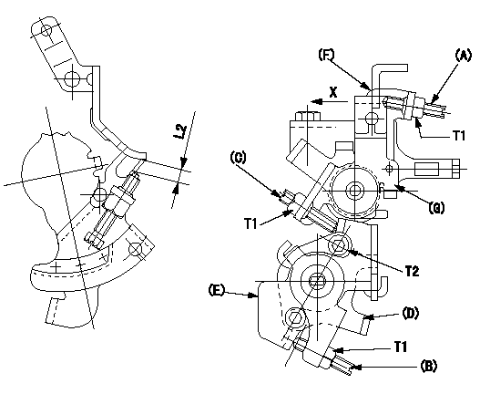
M-CSD adjustment
1. Move the lever E clockwise and when it contacts the stopper D, adjust screw B so that the timer piston advance is a (L1). Then, fix using the nut.
2. With intermediate lever screw (C)'s fixing lever (E) positioned as in 1., pull the intermediate lever in direction X. After confirming that it contacts the stop position, adjust so that screw (C) contacts lever (E) and then fix using the nut.
(In condition (2), intermediate lever: full speed position, at timer advance a.)
Confirm that the timer piston advances to b deg when the intermediate lever is returned.
3. Fast idle adjustment
Pull the intermediate lever in direction x to contact the stopper and adjust the screw (A) so that the gap between the idle set bracket and the idle screw is L2. Fix using the nut.
The gap between the control lever at the idle position and the screw (A) must be L3.
(F) Control lever
(G) Intermediate lever
----------
a=2deg b=0deg L1=1.6mm L2=6+-0.5mm L3=(1.7)mm
----------
T1=6~9N-m(0.6~0.9kgf-m) T2=5~7N-m(0.5~0.7kgf-m) L2=6+-0.5mm
----------
a=2deg b=0deg L1=1.6mm L2=6+-0.5mm L3=(1.7)mm
----------
T1=6~9N-m(0.6~0.9kgf-m) T2=5~7N-m(0.5~0.7kgf-m) L2=6+-0.5mm
0000001901 DASHPOT ADJUSTMENT
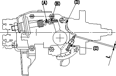
Adjustment of the dash pot
1. Insert a block gauge L (thickness gauge) between the idle set screw (C) and the bracket (D).
2. In the above condition, adjust the locknut (B) so that the dashpot adjusting (A) contacts the pushrod, and then fix the locknut.
Nut tightening torque is T.
3.The dashpot and control lever contact faces must be smooth. Confirm that the control lever returns to the idle position.
----------
L=2.7+-0.05mm T=6~7Nm(0.6~0.7kgfm)
----------
L=2.7+-0.05mm
----------
L=2.7+-0.05mm T=6~7Nm(0.6~0.7kgfm)
----------
L=2.7+-0.05mm
Information:
Start By:a. remove timing gear cover1. Time the engine as follows:a. Install Tool (A) in the flywheel housing.b. Remove the cover from the side of the fuel injection pump housing so the timing pin can be installed. Remove the plug from the flywheel housing so the timing bolt can be installed.c. Turn the engine in the direction of engine rotation until Tool (B) can be installed in fuel injection pump housing and located in the groove in the fuel injection pump camshaft, a 3/8" - 16 NC bolt can be installed in the flywheel through the hole in the flywheel housing, and the "C" marks on the crankshaft gear and the camshaft gear are in alignment with each other. 2. Loosen bolt (1) until there is approximately 3.18 mm (.125 in) gap between washer (2) and fuel pump drive gear (3).3. Install Tool (C) as shown, and loosen the fuel pump drive gear from the taper on the fuel injection pump camshaft. Remove Tool (C), the bolt, washer and fuel pump drive gear.4. Remove the bolts and plate (4) that hold idler gear (5) in position. Remove the idler gear. If necessary, remove the bearing from the idler gear with Tool (D) and a press.
Do not turn the crankshaft after camshaft gear (6) has been removed. Turning the crankshaft will cause damage to the valves.
5. Remove the four bolts that hold camshaft gear (6) to the camshaft. Remove the camshaft gear.Install Timing Gears
1. Make an alignment of the "C" marks on crankshaft gear (3) and camshaft gear (4). Install the camshaft gear and the bolts that hold it. Tighten the bolts to a torque of 55 7 N m (41 5 lb ft).2. Install the bearing in idler gear (1) with Tool (A). The end of the bearing must be 1.52 mm (.060 in) below the face of the gear hub after installation.3. Be sure the oil hole in the shaft for idler gear (1) is open. Put idler gear (1) and plate (2) in position on the shaft. Install the bolts that hold them. 4. Make sure Tool (C) is in position in the groove of the fuel injection pump camshaft.5. Put fuel injection pump drive gear (5) in position on the fuel injection pump camshaft. Put washer (6) in position on the gear with the largest diameter toward the front of the engine. Install bolt (7), and tighten it to a torque of 7 N m (5 lb ft). Make sure bolt (7) does not turn while the flywheel is being turned.6. Remove the timing bolt from the flywheel, and use Tool (B) to turn the flywheel in the opposite direction of engine rotation. Turn the flywheel until the "C" mark on the crankshaft gear moves 30°.7. Turn the flywheel in the direction of engine rotation until the timing bolt can be installed in the flywheel and the "C" marks are in alignment. This will remove all of the backlash from the timing gears.8.
Have questions with 104769-2171?
Group cross 104769-2171 ZEXEL
104769-2171
9 460 610 383
INJECTION-PUMP ASSEMBLY