Information injection-pump assembly
BOSCH
F 01G 09W 00U
f01g09w00u
ZEXEL
104769-2123
1047692123
NISSAN
1670040L01
1670040l01
Rating:
Cross reference number
BOSCH
F 01G 09W 00U
f01g09w00u
ZEXEL
104769-2123
1047692123
NISSAN
1670040L01
1670040l01
Zexel num
Bosch num
Firm num
Name
Calibration Data:
Adjustment conditions
Test oil
1404 Test oil ISO4113orSAEJ967d
1404 Test oil ISO4113orSAEJ967d
Test oil temperature
degC
45
45
50
Nozzle
105000-2010
Bosch type code
NP-DN12SD12TT
Nozzle holder
105780-2080
Opening pressure
MPa
14.7
14.7
15.19
Opening pressure
kgf/cm2
150
150
155
Injection pipe
Inside diameter - outside diameter - length (mm) mm 2-6-840
Inside diameter - outside diameter - length (mm) mm 2-6-840
Transfer pump pressure
kPa
20
20
20
Transfer pump pressure
kgf/cm2
0.2
0.2
0.2
Direction of rotation (viewed from drive side)
Right R
Right R
Injection timing adjustment
Pump speed
r/min
900
900
900
Average injection quantity
mm3/st.
31.3
30.9
31.7
Difference in delivery
mm3/st.
2
Basic
*
Oil temperature
degC
50
48
52
Injection timing adjustment_02
Pump speed
r/min
600
600
600
Average injection quantity
mm3/st.
31.5
29.5
33.5
Oil temperature
degC
50
48
52
Injection timing adjustment_03
Pump speed
r/min
900
900
900
Average injection quantity
mm3/st.
31.3
30.3
32.3
Difference in delivery
mm3/st.
2.5
Basic
*
Oil temperature
degC
50
48
52
Injection timing adjustment_04
Pump speed
r/min
1200
1200
1200
Average injection quantity
mm3/st.
31.3
29.3
33.3
Oil temperature
degC
50
48
52
Injection timing adjustment_05
Pump speed
r/min
2300
2300
2300
Average injection quantity
mm3/st.
29.5
27.5
31.5
Oil temperature
degC
52
50
54
Injection timing adjustment_06
Pump speed
r/min
2500
2500
2500
Average injection quantity
mm3/st.
27.3
25.3
29.3
Oil temperature
degC
55
52
58
Injection quantity adjustment
Pump speed
r/min
2600
2600
2600
Average injection quantity
mm3/st.
19
17
21
Difference in delivery
mm3/st.
4.5
Basic
*
Oil temperature
degC
55
52
58
Injection quantity adjustment_02
Pump speed
r/min
2600
2600
2600
Average injection quantity
mm3/st.
19
15.5
22.5
Difference in delivery
mm3/st.
5
Basic
*
Oil temperature
degC
55
52
58
Injection quantity adjustment_03
Pump speed
r/min
2800
2800
2800
Average injection quantity
mm3/st.
6.5
Oil temperature
degC
55
52
58
Governor adjustment
Pump speed
r/min
350
350
350
Average injection quantity
mm3/st.
7
6
8
Difference in delivery
mm3/st.
0.9
Basic
*
Oil temperature
degC
48
46
50
Governor adjustment_02
Pump speed
r/min
350
350
350
Average injection quantity
mm3/st.
7
5
9
Difference in delivery
mm3/st.
1.4
Oil temperature
degC
48
46
50
Boost compensator adjustment
Pump speed
r/min
900
900
900
Average injection quantity
mm3/st.
9.8
4.8
14.8
Oil temperature
degC
50
48
52
Lever angle (shim thickness)
mm
6
5.95
6.05
Remarks
From idle
From idle
Timer adjustment
Pump speed
r/min
100
100
100
Average injection quantity
mm3/st.
38
38
Difference in delivery
mm3/st.
15
Basic
*
Oil temperature
degC
48
46
50
Timer adjustment_02
Pump speed
r/min
100
100
100
Average injection quantity
mm3/st.
38
38
Difference in delivery
mm3/st.
17
Oil temperature
degC
48
46
50
Speed control lever angle
Pump speed
r/min
350
350
350
Average injection quantity
mm3/st.
0
0
0
Oil temperature
degC
48
46
50
Remarks
Magnet OFF at idling position
Magnet OFF at idling position
Speed control lever angle_02
Pump speed
r/min
900
900
900
Average injection quantity
mm3/st.
0
0
0
Oil temperature
degC
50
48
52
Remarks
Magnet OFF at full-load position
Magnet OFF at full-load position
0000000901
Pump speed
r/min
900
900
900
Overflow quantity
cm3/min
390
260
520
Oil temperature
degC
50
48
52
Stop lever angle
Pump speed
r/min
900
900
900
Pressure
kPa
373
344
402
Pressure
kgf/cm2
3.8
3.5
4.1
Basic
*
Oil temperature
degC
50
48
52
Stop lever angle_02
Pump speed
r/min
900
900
900
Pressure
kPa
372.5
333
412
Pressure
kgf/cm2
3.8
3.4
4.2
Basic
*
Oil temperature
degC
50
48
52
Stop lever angle_03
Pump speed
r/min
1800
1800
1800
Pressure
kPa
578.5
539
618
Pressure
kgf/cm2
5.9
5.5
6.3
Oil temperature
degC
50
48
52
Stop lever angle_04
Pump speed
r/min
2500
2500
2500
Pressure
kPa
745.5
706
785
Pressure
kgf/cm2
7.6
7.2
8
Oil temperature
degC
55
52
58
0000001101
Pump speed
r/min
900
900
900
Timer stroke
mm
1.4
1.2
1.6
Basic
*
Oil temperature
degC
50
48
52
_02
Pump speed
r/min
900
900
900
Timer stroke
mm
1.4
1.1
1.7
Basic
*
Oil temperature
degC
50
48
52
_03
Pump speed
r/min
1200
1200
1200
Timer stroke
mm
3.3
2.9
3.7
Oil temperature
degC
50
48
52
_04
Pump speed
r/min
2300
2300
2300
Timer stroke
mm
8.55
8.1
9
Oil temperature
degC
52
50
54
0000001201
Max. applied voltage
V
8
8
8
Test voltage
V
13
12
14
Timing setting
K dimension
mm
3.3
3.2
3.4
KF dimension
mm
6.64
6.54
6.74
MS dimension
mm
1.8
1.7
1.9
Control lever angle alpha
deg.
23
19
27
Control lever angle beta
deg.
42
37
47
Test data Ex:
0000001801 W-CSD ADJUSTMENT
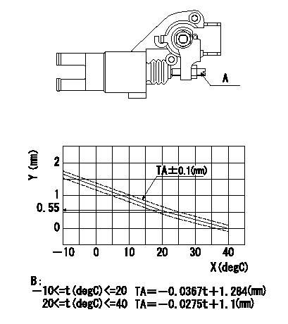
Adjustment of the W-CSD
Adjust the timer stroke using the screw so that it is as determined from the graph.
Caution: The temperature of the wax at adjustment must not exceed a.
A:Screw
B:Timer stroke graph
X:Temperature t
Y:Timer stroke TA
----------
a=30degC
----------
----------
a=30degC
----------
0000001901 DASHPOT ADJUSTMENT
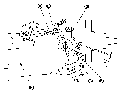
(1)Adjustment of the dash pot
1. Insert a block gauge L1 between the idle set screw (C) and the bracket (D).
2. In the above condition, adjust the locknut (B) so that the dashpot adjusting (A) contacts the pushrod, and then fix the locknut (Tightening torque T).
3.The dashpot and control lever contact faces must be smooth. Confirm that the control lever returns to the idle position.
(2)ISC actuator installation
In the idle position, fix the actuator bracket (F) so that the clearance between the control lever and the ISC lever roller (E) is L2.
----------
L1=2.7+-0.05(mm) L2=1.0+1.0-0.5(mm) T=6~7(N-m)(0.6~0.7(kgf-m))
----------
L1=2.7+-0.05(mm) L2=1.0+1.0-0.5(mm)
----------
L1=2.7+-0.05(mm) L2=1.0+1.0-0.5(mm) T=6~7(N-m)(0.6~0.7(kgf-m))
----------
L1=2.7+-0.05(mm) L2=1.0+1.0-0.5(mm)
0000002001 POTENTIOMETER ADJUSTMENT
Adjustment of the potentiometer
Measure the injection quantity at pump speed N and the control lever positioned a from the idle position (gap L)
Determine the voltage with the conversion formula and adjust the potentiometer.
Voltage conversion formula: V+-0.05 = 0.092Q+1.414 Q<=17 (mm3/st)
V+-0.05 = 0.0758Q + 1.69 Q>17(mm3/st) (V: voltage, Q: injection quantity)
----------
N=600(r/min) a=11(deg) L=6(mm)
----------
----------
N=600(r/min) a=11(deg) L=6(mm)
----------
Information:
Start By:a. remove governor 1. Remove the bolts and the plate from the side of the fuel injection pump housing.2. Install Tool (A) in the fuel injection pump housing. Move the rack until Tool (A) can be installed to hold the rack in the center position. The rack must be in the center position to remove the fuel injection pumps.3. Use Tool (B) to remove bushing (1) from the fuel injection pump housing.4. Remove the O-ring seal from the fuel injection pump housing. Spacers (2) are the same thickness for each fuel injection pump so they can be mixed. The fuel injection pump plungers and barrels are sets and can not be mixed.5. Install Tool (C) on the bonnet. Remove the fuel injection pump. 6. Remove spacer (2) from the fuel injection pump housing.7. Do Steps 3 through 6 to remove the other fuel injection pumps.Install Fuel Injection Pumps
1. Install spacer (1) in the fuel injection pump housing. 2. Install Tool (A) in the fuel injection pump housing. Move the rack until Tool (A) can be installed to hold the rack in the center position. The rack must be in the center position to install the fuel injection pumps.3. Turn the camshaft until the lobe of the camshaft is down for the pump to be installed.4. Install Tool (B) on the bonnet of the fuel injection pump.5. Install the fuel injection pump in the pump housing with saw cut (slot) (3) in the gear in alignment with the small pin (2) and groove (4) in the barrel in alignment with dowel (5) in the pump housing. 6. Put clean oil on O-ring seal (6). Install it in the fuel injection pump housing.7. Install the bushing by hand until it is even with the top of the housing. If the bushing can not be installed this far by hand, remove it. Remove the fuel injection pump, and put the pump in alignment again, and install the bushing again. 8. Install Tool (C) on the bushing and tighten the bushing to a torque of 190 14 N m (140 10 lb ft). 9. Install Tool (D) to measure total rack travel. Correct rack travel is 15.7 mm (.618 in). A smaller measurement is an indication of incorrect fuel injection pump installation.10. Do Steps 1 through 9 again for installation of the other fuel pumps.11. Install the cover and gasket on the fuel injection pump housing.End By:a. install governorDisassemble Fuel Injection Pumps
Start By:a. remove fuel injection pumps
Be careful when the injection pumps are disassembled. Do not damage the surfaces of the plungers, barrels and bonnets. Any scratches will cause leakage inside the fuel injection pump. The plunger and barrel for each pump are made as a set. Do not put the plunger of one pump in the barrel of another pump. If one part has wear, install a complete new pump assembly. Be careful when the plunger is put into the bore of the barrel.
1. Pull plunger (1) and