Information injection-pump assembly
BOSCH
9 460 610 162
9460610162
ZEXEL
104769-2110
1047692110
NISSAN
16700V7202
16700v7202
Rating:
Cross reference number
BOSCH
9 460 610 162
9460610162
ZEXEL
104769-2110
1047692110
NISSAN
16700V7202
16700v7202
Zexel num
Bosch num
Firm num
Name
Calibration Data:
Adjustment conditions
Test oil
1404 Test oil ISO4113orSAEJ967d
1404 Test oil ISO4113orSAEJ967d
Test oil temperature
degC
45
45
50
Nozzle
105000-2010
Bosch type code
NP-DN12SD12TT
Nozzle holder
105780-2080
Opening pressure
MPa
14.7
14.7
15.19
Opening pressure
kgf/cm2
150
150
155
Injection pipe
Inside diameter - outside diameter - length (mm) mm 2-6-840
Inside diameter - outside diameter - length (mm) mm 2-6-840
Transfer pump pressure
kPa
20
20
20
Transfer pump pressure
kgf/cm2
0.2
0.2
0.2
Direction of rotation (viewed from drive side)
Right R
Right R
Injection timing adjustment
Pump speed
r/min
900
900
900
Average injection quantity
mm3/st.
31.4
30.9
31.9
Difference in delivery
mm3/st.
2.5
Basic
*
Injection timing adjustment_02
Pump speed
r/min
2600
2600
2600
Average injection quantity
mm3/st.
18.5
15
22
Injection timing adjustment_03
Pump speed
r/min
2300
2300
2300
Average injection quantity
mm3/st.
29.1
27.1
31.1
Injection timing adjustment_04
Pump speed
r/min
900
900
900
Average injection quantity
mm3/st.
31.4
30.4
32.4
Injection timing adjustment_05
Pump speed
r/min
600
600
600
Average injection quantity
mm3/st.
31.1
29.1
33.1
Injection quantity adjustment
Pump speed
r/min
2600
2600
2600
Average injection quantity
mm3/st.
18.5
15.5
21.5
Basic
*
Injection quantity adjustment_02
Pump speed
r/min
2800
2800
2800
Average injection quantity
mm3/st.
5
Governor adjustment
Pump speed
r/min
350
350
350
Average injection quantity
mm3/st.
7.3
5.8
8.8
Basic
*
Governor adjustment_02
Pump speed
r/min
350
350
350
Average injection quantity
mm3/st.
7.3
5.3
9.3
Difference in delivery
mm3/st.
1.6
Governor adjustment_03
Pump speed
r/min
500
500
500
Average injection quantity
mm3/st.
4
Boost compensator adjustment
Pump speed
r/min
900
900
900
Average injection quantity
mm3/st.
7.5
2.5
12.5
Remarks
From idle
From idle
Timer adjustment
Pump speed
r/min
100
100
100
Average injection quantity
mm3/st.
44.8
40.8
48.8
Basic
*
Remarks
Refer to additional devices.
Refer to additional devices.
Speed control lever angle
Pump speed
r/min
350
350
350
Average injection quantity
mm3/st.
0
0
0
Remarks
Magnet OFF
Magnet OFF
0000000901
Pump speed
r/min
900
900
900
Overflow quantity
cm3/min
390
258
522
Stop lever angle
Pump speed
r/min
900
900
900
Pressure
kPa
372.5
343
402
Pressure
kgf/cm2
3.8
3.5
4.1
Basic
*
Stop lever angle_02
Pump speed
r/min
900
900
900
Pressure
kPa
372.5
333
412
Pressure
kgf/cm2
3.8
3.4
4.2
Stop lever angle_03
Pump speed
r/min
1800
1800
1800
Pressure
kPa
588.5
549
628
Pressure
kgf/cm2
6
5.6
6.4
Stop lever angle_04
Pump speed
r/min
2500
2500
2500
Pressure
kPa
735.5
696
775
Pressure
kgf/cm2
7.5
7.1
7.9
0000001101
Pump speed
r/min
900
900
900
Timer stroke
mm
1.3
1.1
1.5
Basic
*
_02
Pump speed
r/min
900
900
900
Timer stroke
mm
1.3
1
1.6
_03
Pump speed
r/min
1200
1200
1200
Timer stroke
mm
3.1
2.7
3.5
_04
Pump speed
r/min
2300
2300
2300
Timer stroke
mm
8.55
8.1
9
0000001201
Max. applied voltage
V
8
8
8
Test voltage
V
13
12
14
Timing setting
K dimension
mm
3.3
3.2
3.4
KF dimension
mm
6.64
6.54
6.74
MS dimension
mm
1.8
1.7
1.9
Control lever angle alpha
deg.
25
21
29
Control lever angle beta
deg.
44
39
49
Control lever angle gamma
From idle deg. 11 10.5 11.5
From idle deg. 11 10.5 11.5
Test data Ex:
0000001801 W-CSD ADJUSTMENT
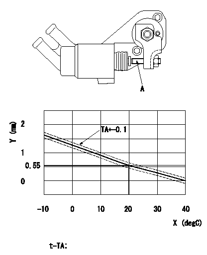
Adjustment of the W-CSD
Adjust the timer stroke determined from the graph below using the screw.
Caution: The temperature of the wax at adjustment must not exceed a.
A = screw
Y = timer stroke TA
X = temperature t
----------
a=30degC
----------
t-TA;-10<=t(degC)<=20 TA=-0.0367t+1.284 20<=t(degC)<=40 TA=-0.0275t+1.1
----------
a=30degC
----------
t-TA;-10<=t(degC)<=20 TA=-0.0367t+1.284 20<=t(degC)<=40 TA=-0.0275t+1.1
0000001901 DASHPOT ADJUSTMENT
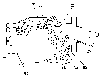
Adjustment of the dash pot
1. Insert a block gauge L1 (thickness gauge) between the idle set screw and the bracket.
2. In the above condition, adjust the elongated hole so that the pushrod contacts the control lever. Then, fix using the bolt.
TT
Note:
(1)The dashpot and control lever contact faces must be smooth.
(2)Confirm that the control lever returns to the idling position.
ISC actuator installation
1. Maintain the control lever in the idling position.
2. Fix the actuator bracket (A) so that the clearance between the control lever and the ISC lever's roller (B) is L2.
----------
L1=3.8+-0.05mm L2=1.5+-0.5mm T=6~9N-m{0.6~0.9kgf-m}
----------
L1=3.8+-0.05mm L2=1.5+-0.5mm
----------
L1=3.8+-0.05mm L2=1.5+-0.5mm T=6~9N-m{0.6~0.9kgf-m}
----------
L1=3.8+-0.05mm L2=1.5+-0.5mm
0000002001 STARTING I/Q ADJUSTMENT
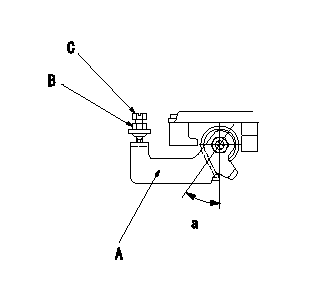
Starting injection quantity adjustment
Fix the stop lever's starting injection quantity adjusting bolt. At adjustment, adjust the bolt so that the starting injection quantity is as specified and then fix using the locknut.
A = stop lever
B = locknut
C = adjusting bolt
----------
----------
a=32+-4deg
----------
----------
a=32+-4deg
Information:
2. Turn the crankshaft until two pistons are at bottom center.3. Remove bolts (1) and the bearing caps. Push the rods and pistons up until the rings are out of the cylinder liners. 4. Remove pistons (2) and connecting rods from the cylinder liners.5. Do Steps 1 through 4 for the remainder of the pistons and connecting rods.Install Pistons & Connecting Rod Assemblies
1. Put clean engine oil on piston rings, connecting rod bearings and cylinder liners. 2. Use Tool (A), and install piston (2) and the connecting rod in the cylinder liner.3. Install the bearing cap on the connecting rod with the number on the side of the bearing cap on the same side and same number as on the connecting rod.4. Put 2P2506 Thread Lubricant on the threads of the bolts. Install the nuts, and tighten them to a torque of 90 8 N m (67 6 lb ft). Put a mark on the nuts and cap, and tighten the nuts an extra 90 5 degrees.5. Do Steps 1 through 4 for the remainder of the pistons and connecting rods.End By:a. install piston cooling tubesb. install oil pumpc. install cylinder head assemblyDisassemble & Assemble Pistons & Connecting Rod Assemblies
Start By:a. remove pistons and connecting rod assemblies 1. Remove bearings (3) from the connecting rod and connecting rod cap.2. Remove retainer ring (1) with Tool (A).3. Remove pin (2) and connecting rod (4) from the piston. 4. Remove piston rings (5) from the piston with Tool (B). Clean the piston ring grooves on the pistons with an acceptable ring groove cleaning tool. See, Use Of Piston Bearing Removal And Installation Tools, Special Instructions, SMHS7295.5. Heat connecting rod (4) in an oven to a temperature of 177° to 260°C (350° to 500° F). Never use a direct flame to heat a connecting rod. 6. Put connecting rod (4) in position on the base plate of Tool (C). Put a new rod pin bearing (6) on the adapter part of Tool (C). The old bearing is pushed out by Tool (C) as the new bearing is installed.7. Use Tool (C) to push the new bearing into the connecting rod until the push adapter of Tool (C) makes full contact with the connecting rod surface.8. Use a pin boring machine to make the rod pin bearing the correct size. The bore in the new rod pin bearing must be 50.830 0.008 mm (2.0012 .0003 in).9. Check the clearance between the ends of the piston rings. See the topic, "Pistons & Rings" in Specifications Manual, SENR6470.10. Install the oil ring spring in the oil ring groove of the piston. The oil ring is to be installed over the spring with the oil ring end gap 180° from the oil ring spring joint.11. Install the oil ring on the piston with tool (B).12. Install the second (intermediate) piston ring with the side that has the identification "UP-2" toward the top of the piston. Use Tool (B) to install