Information injection-pump assembly
ZEXEL
104769-2080
1047692080
Rating:
Components :
| 0. | INJECTION-PUMP ASSEMBLY | 104769-2080 |
| 1. | _ | |
| 2. | FUEL INJECTION PUMP | |
| 3. | NUMBER PLATE | 146644-5700 |
| 4. | _ | |
| 5. | CAPSULE | |
| 6. | ADJUSTING DEVICE | |
| 7. | NOZZLE AND HOLDER ASSY | 105141-2512 |
| 8. | Nozzle and Holder | 16600-05E26 |
| 9. | Open Pre:MPa(Kqf/cm2) | 12.7{130} |
| 10. | NOZZLE-HOLDER | 105071-0681 |
| 11. | NOZZLE | 105000-1871 |
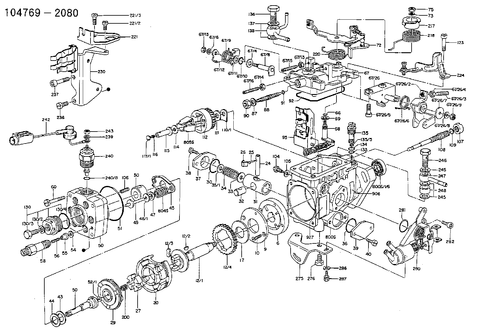
Scheme ###:
| 1. | [1] | 146005-0820 | PUMP HOUSING 3K D20 LL R L/ |
| 1/6. | [1] | 146601-0100 | PACKING RING |
| 6. | [1] | 146100-0120 | SUPPLY PUMP D20 |
| 9. | [1] | 146103-0000 | COVER |
| 10. | [2] | 139104-0000 | FLAT-HEAD SCREW |
| 12. | [1] | 146200-0420 | DRIVE SHAFT D20 LL |
| 12/1. | [1] | 146200-0400 | DRIVE SHAFT |
| 12/2. | [1] | 146201-0000 | WOODRUFF KEY |
| 12/3. | [2] | 146202-0100 | DAMPER |
| 12/4. | [1] | 146203-0000 | TOOTHED GEAR |
| 17. | [1] | 146204-0000 | PLAIN WASHER |
| 20. | [1] | 146210-0820 | ROLLER SET |
| 24. | [1] | 146303-0000 | BEARING PIN |
| 25. | [1] | 146304-0000 | BEARING PIN |
| 26. | [1] | 146305-0000 | CLAMPING BAND |
| 27. | [1] | 146205-0000 | SLOTTED WASHER |
| 29. | [1] | 146221-0120 | CAM PLATE '01'Y490 |
| 30. | [1] | 146600-0800 | O-RING |
| 31. | [1] | 146300-1700 | PUMP PLUNGER ' 17' 5-10. |
| 32. | [1] | 146301-0000 | SLIDING PIECE |
| 33. | [1] | 146603-0700 | SHIM |
| 34. | [1] | 146302-0000 | COMPRESSION SPRING K=2.05 |
| 35. | [1] | 029998-0710 | SHIM |
| 35/1. | [1] | 146603-0700 | SHIM |
| 35/1. | [1] | 146603-0800 | SHIM |
| 35/1. | [1] | 146603-0900 | SHIM |
| 35/1. | [1] | 146603-1000 | SHIM |
| 35/1. | [1] | 146603-1100 | SHIM |
| 35/1. | [1] | 146603-3600 | SHIM |
| 36. | [1] | 146600-0800 | O-RING |
| 37. | [1] | 146310-0000 | COVER |
| 38. | [2] | 139106-0000 | FLAT-HEAD SCREW |
| 39. | [1] | 146310-0100 | COVER |
| 40. | [2] | 139106-0000 | FLAT-HEAD SCREW |
| 43. | [1] | 146230-0000 | SHIM |
| 44. | [1] | 146230-0100 | PLAIN WASHER |
| 45. | [1] | 146231-0000 | SLOTTED WASHER |
| 47. | [2] | 146233-0000 | SLOTTED WASHER |
| 48. | [2] | 029998-0570 | SHIM |
| 48/1. | [1] | 146603-0000 | SHIM |
| 48/1. | [1] | 146603-0100 | SHIM |
| 48/1. | [1] | 146603-0200 | SHIM |
| 48/1. | [1] | 146603-0300 | SHIM |
| 48/1. | [1] | 146603-0400 | SHIM |
| 48/1. | [1] | 146603-0500 | SHIM |
| 48/1. | [1] | 146603-0600 | SHIM |
| 49. | [2] | 146234-0020 | GUIDE PIN |
| 50. | [1] | 146405-1220 | HYDRAULIC HEAD NMC GY1 |
| 50. | [1] | 146405-1220 | HYDRAULIC HEAD NMC GY1 |
| 50. | [1] | 146405-1220 | HYDRAULIC HEAD NMC GY1 |
| 51. | [1] | 146600-0000 | O-RING |
| 52. | [1] | 029998-0330 | SHIM |
| 52/1. | [1] | 146490-0000 | SHIM |
| 52/1. | [1] | 146490-0100 | SHIM |
| 52/1. | [1] | 146490-0200 | SHIM |
| 52/1. | [1] | 146490-0300 | SHIM |
| 52/1. | [1] | 146490-0400 | SHIM |
| 52/1. | [1] | 146490-0500 | SHIM |
| 52/1. | [1] | 146490-0600 | SHIM |
| 52/1. | [1] | 146490-0700 | SHIM |
| 52/1. | [1] | 146490-0800 | SHIM |
| 52/1. | [1] | 146490-0900 | SHIM |
| 52/1. | [1] | 146490-1000 | SHIM |
| 52/1. | [1] | 146490-1100 | SHIM |
| 52/1. | [1] | 146490-1200 | SHIM |
| 52/1. | [1] | 146490-1300 | SHIM |
| 52/1. | [1] | 146490-1400 | SHIM |
| 52/1. | [1] | 146490-1500 | SHIM |
| 52/1. | [1] | 146490-1600 | SHIM |
| 52/1. | [1] | 146490-1700 | SHIM |
| 52/1. | [1] | 146490-1800 | SHIM |
| 52/1. | [1] | 146490-1900 | SHIM |
| 52/1. | [1] | 146490-2000 | SHIM |
| 52/1. | [1] | 146490-2100 | SHIM |
| 52/1. | [1] | 146490-2200 | SHIM |
| 52/1. | [1] | 146490-2300 | SHIM |
| 52/1. | [1] | 146490-2400 | SHIM |
| 52/1. | [1] | 146490-2500 | SHIM |
| 52/1. | [1] | 146490-2600 | SHIM |
| 52/1. | [1] | 146490-2700 | SHIM |
| 52/1. | [1] | 146490-2800 | SHIM |
| 52/1. | [1] | 146490-2900 | SHIM |
| 52/1. | [1] | 146490-3000 | SHIM |
| 52/1. | [1] | 146490-3100 | SHIM |
| 52/1. | [1] | 146490-3200 | SHIM |
| 52/1. | [1] | 146490-3300 | SHIM |
| 52/1. | [1] | 146490-3400 | SHIM |
| 52/1. | [1] | 146490-3500 | SHIM |
| 52/1. | [1] | 146490-3600 | SHIM |
| 52/1. | [1] | 146490-3700 | SHIM |
| 52/1. | [1] | 146490-3800 | SHIM |
| 52/1. | [1] | 146490-3900 | SHIM |
| 52/1. | [1] | 146490-4000 | SHIM |
| 52/1. | [1] | 146490-4100 | SHIM |
| 52/1. | [1] | 146490-4200 | SHIM |
| 52/1. | [1] | 146490-4300 | SHIM |
| 52/1. | [1] | 146490-4400 | SHIM |
| 52/1. | [1] | 146490-4500 | SHIM |
| 52/1. | [1] | 146490-4600 | SHIM |
| 52/1. | [1] | 146490-4700 | SHIM |
| 52/1. | [1] | 146490-4800 | SHIM |
| 52/1. | [1] | 146490-4900 | SHIM |
| 52/1. | [1] | 146490-5000 | SHIM |
| 54. | [6] | 146433-0100 | GASKET |
| 55. | [6] | 146430-0120 | DELIVERY-VALVE ASSEMBLY 'VE2' VR25 |
| 56. | [6] | 146432-0000 | COMPRESSION SPRING K=0.48 |
| 58. | [6] | 146440-0220 | FITTING D0.45 L=50 |
| 60. | [3] | 139106-0100 | FLAT-HEAD SCREW |
| 66. | [1] | 146600-0100 | O-RING |
| 67. | [1] | 146502-7220 | GOVERNOR COVER GY1 TAJIMA |
| 67/4. | [1] | 139310-0200 | PLAIN WASHER |
| 67/6. | [1] | 014110-6440 | LOCKING WASHER D12.2&6.1T1.5 |
| 67/8. | [1] | 146515-1820 | LEVER SHAFT |
| 67/9. | [1] | 146587-4500 | COILED SPRING |
| 67/10. | [1] | 146600-0200 | O-RING |
| 67/11. | [1] | 146602-0100 | PLAIN WASHER |
| 67/12. | [1] | 146540-1800 | CONTROL LEVER |
| 67/12B. | [1] | 146540-1900 | CONTROL LEVER ' 0' |
| 67/13. | [1] | 146621-1700 | UNION NUT |
| 67/13. | [1] | 146621-1700 | UNION NUT |
| 67/14. | [1] | 146621-1800 | UNION NUT |
| 67/16. | [1] | 146526-3800 | BLEEDER SCREW AUTO L=45 FULL |
| 67/26. | [1] | 146625-7220 | BRACKET |
| 67/26/2. | [1] | 146616-4320 | CONTROL LEVER |
| 67/26/3. | [1] | 146620-1400 | FLAT-HEAD SCREW |
| 67/26/4. | [1] | 013020-6040 | UNION NUT |
| 67/26/5. | [2] | 010206-2540 | HEX-SOCKET-HEAD CAP SCREW |
| 67/26/6. | [1] | 146587-5200 | COILED SPRING |
| 67/26/7. | [1] | 146602-2000 | PLAIN WASHER |
| 67/26/8. | [1] | 014110-5440 | LOCKING WASHER |
| 67/26/9. | [1] | 013020-5240 | UNION NUT |
| 68. | [1] | 146510-4320 | CONTROL SHAFT R=10 S R |
| 69. | [1] | 139310-0200 | PLAIN WASHER |
| 72. | [1] | 146534-0320 | CONTROL LEVER '403' |
| 72B. | [1] | 146534-0420 | CONTROL LEVER '404' |
| 73. | [1] | 014110-6440 | LOCKING WASHER D12.2&6.1T1.5 |
| 75. | [1] | 013020-6040 | UNION NUT |
| 87. | [1] | 139308-0300 | PLAIN WASHER |
| 88. | [1] | 146545-2120 | THREADED PIN |
| 90. | [1] | 139208-0100 | UNION NUT |
| 91. | [1] | 146600-1200 | O-RING |
| 92. | [1] | 146600-1000 | SEAL RING |
| 95. | [1] | 146561-1120 | FULCRUM LEVER I=2.2 |
| 104. | [2] | 146568-0000 | SLOTTED SPRING PIN |
| 105. | [2] | 026508-1140 | GASKET |
| 106. | [2] | 146588-0000 | COILED SPRING |
| 107. | [1] | 146569-0100 | UNION NUT |
| 108. | [1] | 146570-0320 | GOVERNOR SHAFT L-L/T |
| 109. | [1] | 146600-0400 | O-RING |
| 110. | [1] | 029998-4130 | SHIM |
| 110/1. | [1] | 146571-0000 | SHIM |
| 110/1. | [1] | 146571-0100 | SHIM |
| 110/1. | [1] | 146571-0200 | SHIM |
| 110/1. | [1] | 146571-0300 | SHIM |
| 110/1. | [1] | 146571-0400 | SHIM |
| 110/1. | [1] | 146571-0500 | SHIM |
| 110/1. | [1] | 146571-0600 | SHIM |
| 110/1. | [1] | 146571-0700 | SHIM |
| 110/1. | [1] | 146571-0800 | SHIM |
| 111. | [1] | 146602-0600 | PLAIN WASHER |
| 112. | [1] | 146572-0020 | FLYWEIGHT ASSEMBLY |
| 114. | [1] | 146602-0500 | PLAIN WASHER |
| 115. | [1] | 146575-1500 | SLIDING SLEEVE '15' D0.8G2-0.3 |
| 116. | [1] | 146576-0200 | CAP |
| 117. | [1] | 029998-5510 | PLUG SKH51 |
| 117/1. | [1] | 146577-1800 | PLUG |
| 117/1. | [1] | 146577-1900 | PLUG |
| 117/1. | [1] | 146577-2000 | PLUG |
| 117/1. | [1] | 146577-2100 | PLUG |
| 117/1. | [1] | 146577-2200 | PLUG |
| 117/1. | [1] | 146577-2300 | PLUG |
| 117/1. | [1] | 146577-2400 | PLUG |
| 117/1. | [1] | 146577-2500 | PLUG |
| 117/1. | [1] | 146577-2600 | PLUG |
| 117/1. | [1] | 146577-2700 | PLUG |
| 117/1. | [1] | 146577-2800 | PLUG |
| 117/1. | [1] | 146577-2900 | PLUG |
| 117/1. | [1] | 146577-3000 | PLUG |
| 117/1. | [1] | 146577-3100 | PLUG |
| 117/1. | [1] | 146577-3200 | PLUG |
| 117/1. | [1] | 146577-3300 | PLUG |
| 123. | [4] | 139106-0200 | FLAT-HEAD SCREW |
| 130. | [1] | 146421-0020 | CAPSULE D14 |
| 130/2. | [1] | 026508-1140 | GASKET |
| 130/3. | [1] | 146422-0000 | BLEEDER SCREW |
| 130/4. | [1] | 146600-0500 | O-RING |
| 133. | [1] | 146600-0600 | O-RING |
| 134. | [1] | 146600-0700 | O-RING |
| 135. | [1] | 146110-0220 | CONTROL VALVE '02'4XD1.6K=1.5 |
| 135/5. | [1] | 146114-0000 | SPRING WASHER |
| 136. | [1] | 146120-0220 | OVER FLOW VALVE |
| 137. | [2] | 139512-0200 | GASKET |
| 138. | [1] | 146609-3421 | INLET UNION OUT B1 B1 |
| 200. | [1] | 146206-0100 | COILED SPRING |
| 217. | [1] | 146541-3100 | SLOTTED WASHER |
| 218. | [1] | 146587-5500 | COILED SPRING |
| 219. | [1] | 146541-3000 | BUSHING |
| 220. | [1] | 146587-4300 | COILED SPRING |
| 221. | [1] | 146625-3520 | BRACKET |
| 221/3. | [1] | 139106-0000 | FLAT-HEAD SCREW |
| 221/4. | [1] | 139106-0300 | FLAT-HEAD SCREW |
| 224. | [1] | 146626-6120 | BRACKET |
| 230. | [1] | 146625-5722 | BRACKET |
| 236. | [1] | 139106-0500 | FLAT-HEAD SCREW |
| 237. | [1] | 146620-0200 | HEX-SOCKET-HEAD CAP SCREW |
| 239. | [1] | 023500-5140 | PLAIN WASHER |
| 240. | [1] | 146650-0720 | PULLING ELECTROMAGNET |
| 240/8. | [1] | 146600-1700 | O-RING |
| 242. | [1] | 146658-2820 | WIRE ' 28' 12V |
| 243. | [1] | 013020-5240 | UNION NUT |
| 245. | [3] | 139512-0200 | GASKET |
| 245. | [3] | 139512-0200 | GASKET |
| 246. | [1] | 139812-0500 | EYE BOLT |
| 247. | [1] | 146610-1921 | INLET UNION IN B3 |
| 248. | [1] | 146614-0200 | SPACER BUSHING |
| 275. | [1] | 146612-2200 | BRACKET |
| 276. | [2] | 010010-1640 | BLEEDER SCREW |
| 280. | [1] | 146360-1521 | START ADVANCE ASSY HURUKAWA 2DEG |
| 281. | [1] | 146600-0800 | O-RING |
| 282. | [2] | 010206-1240 | HEX-SOCKET-HEAD CAP SCREW |
| 286. | [1] | 014010-6140 | PLAIN WASHER |
| 287. | [1] | 020106-1440 | BLEEDER SCREW |
| 800S. | [1] | 146009-4820 | PUMP HOUSING |
| 800S/1. | [1] | 146005-0820 | PUMP HOUSING 3K D20 LL R L/ |
| 800S/1/6. | [1] | 146601-0100 | PACKING RING |
| 804S. | [1] | 146232-0320 | COMPRESSION SPRING |
| 805S. | [1] | 146574-0120 | PARTS SET |
| 810S. | [1] | 146600-1120 | REPAIR SET |
| 906. | [1] | 146644-5700 | NUMBER PLATE LD28 SKILINE 69 |
Include in #2:
104769-2080
as INJECTION-PUMP ASSEMBLY
Cross reference number
Zexel num
Bosch num
Firm num
Name
Information:
Assemble Governor
*Pump and Governor Reconditioning Tool Group1. Put the fuel injection pump housing in position on Tool (A). Install race (3), bearing (2) and race (1) on the end of the camshaft in the fuel injection pump housing. 2. Put flyweights (5) in position on carrier assembly (4), and install dowels (6) to hold the flyweights in place. The flyweights must move freely on the dowels and have 0.010 to 0.230 mm (.0004 to .0090 in) end play. 3. Install governor shaft (7) on carrier assembly (4). 4. Install dowel (8) in governor shaft (7), and slide carrier assembly (4) down on the governor shaft until dowel (8) fits into the slot in the carrier assembly.5. Install carrier assembly (4) on the end of the camshaft. 6. Install race (12), bearing (11), race (10) and ring (9) on riser (13). 7. Install riser (13) and spring (14), if equipped, on the governor shaft. 8. Install spool (18) and ring (19) on seat (17), and use Tool (B) to install ring (20) to hold them in position.9. Install seat (17) on spring (16) and spring (16) on shield (15). 10. Install dashpot assembly (21) on the governor shaft. 11. Install ring (22) in the groove on the governor shaft. Install sleeve (23), spring (25), the sleeve and bearing (24) on the governor shaft. 12. Use Tool (C) to hold spring (25) under compression, and install the ring in the groove on the governor shaft. 13. Install O-ring seal (26) on sleeve (27). Install piston (29) and sleeve (27) in the governor servo as shown.14. Install valve (28) in the governor servo as shown. 15. Install lockring (33) in the groove near the center of valve (28). Put sleeve (34), spring broken link spring (35) and seat (36) in position on valve (28), and install lockring (37) to hold them in place. 16. Put governor servo (30) in position on the fuel injection pump housing with piston (29) engaged over the rack. Make sure the lever is engaged in the slot groove of riser (13). 17. If dowel (43) was removed, install it in block (44) 31 0.5 mm (1.22 .02 in) above the outside surface of the block.18. Install bolt (45) in block (44) and spring (38) on bolt (45).19. Install stop screw (40) and the locknut on collar (42). Install power setting screw (41) and the locknut on the collar.20. Install collar (42) on bolt (45). Make an alignment of the hole in the collar with the notch in bolt (45), and install bolt (39). 21. If the dowels that align block (44) with the front governor housing were removed, install them 4.0 0.5 mm (.16 .02 in) above the outside surface of the front governor housing.22. Put block (44) in position on the front governor housing with the holes in the block in alignment with dowels in the front governor housing. 23. Install dowels (46) in the front governor housing 6.0 0.5
*Pump and Governor Reconditioning Tool Group1. Put the fuel injection pump housing in position on Tool (A). Install race (3), bearing (2) and race (1) on the end of the camshaft in the fuel injection pump housing. 2. Put flyweights (5) in position on carrier assembly (4), and install dowels (6) to hold the flyweights in place. The flyweights must move freely on the dowels and have 0.010 to 0.230 mm (.0004 to .0090 in) end play. 3. Install governor shaft (7) on carrier assembly (4). 4. Install dowel (8) in governor shaft (7), and slide carrier assembly (4) down on the governor shaft until dowel (8) fits into the slot in the carrier assembly.5. Install carrier assembly (4) on the end of the camshaft. 6. Install race (12), bearing (11), race (10) and ring (9) on riser (13). 7. Install riser (13) and spring (14), if equipped, on the governor shaft. 8. Install spool (18) and ring (19) on seat (17), and use Tool (B) to install ring (20) to hold them in position.9. Install seat (17) on spring (16) and spring (16) on shield (15). 10. Install dashpot assembly (21) on the governor shaft. 11. Install ring (22) in the groove on the governor shaft. Install sleeve (23), spring (25), the sleeve and bearing (24) on the governor shaft. 12. Use Tool (C) to hold spring (25) under compression, and install the ring in the groove on the governor shaft. 13. Install O-ring seal (26) on sleeve (27). Install piston (29) and sleeve (27) in the governor servo as shown.14. Install valve (28) in the governor servo as shown. 15. Install lockring (33) in the groove near the center of valve (28). Put sleeve (34), spring broken link spring (35) and seat (36) in position on valve (28), and install lockring (37) to hold them in place. 16. Put governor servo (30) in position on the fuel injection pump housing with piston (29) engaged over the rack. Make sure the lever is engaged in the slot groove of riser (13). 17. If dowel (43) was removed, install it in block (44) 31 0.5 mm (1.22 .02 in) above the outside surface of the block.18. Install bolt (45) in block (44) and spring (38) on bolt (45).19. Install stop screw (40) and the locknut on collar (42). Install power setting screw (41) and the locknut on the collar.20. Install collar (42) on bolt (45). Make an alignment of the hole in the collar with the notch in bolt (45), and install bolt (39). 21. If the dowels that align block (44) with the front governor housing were removed, install them 4.0 0.5 mm (.16 .02 in) above the outside surface of the front governor housing.22. Put block (44) in position on the front governor housing with the holes in the block in alignment with dowels in the front governor housing. 23. Install dowels (46) in the front governor housing 6.0 0.5