Information injection-pump assembly
ZEXEL
104769-2060
1047692060
Rating:
Components :
| 0. | INJECTION-PUMP ASSEMBLY | 104769-2060 |
| 1. | _ | |
| 2. | FUEL INJECTION PUMP | |
| 3. | NUMBER PLATE | 146644-4900 |
| 4. | _ | |
| 5. | CAPSULE | |
| 6. | ADJUSTING DEVICE | |
| 7. | NOZZLE AND HOLDER ASSY | 105141-2512 |
| 8. | Nozzle and Holder | 16600-05E26 |
| 9. | Open Pre:MPa(Kqf/cm2) | 12.7{130} |
| 10. | NOZZLE-HOLDER | 105071-0681 |
| 11. | NOZZLE | 105000-1871 |
Scheme ###:
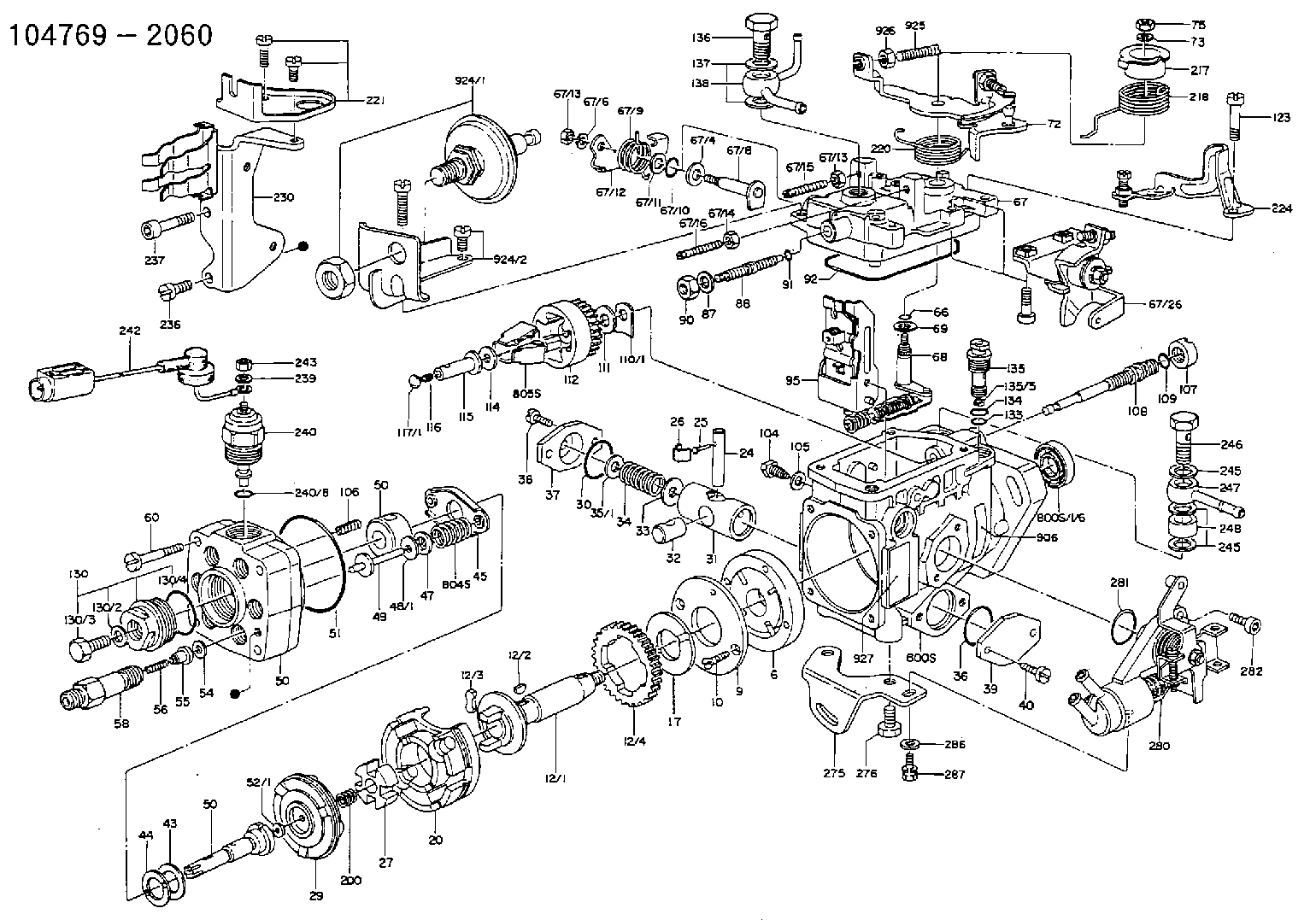
| 1. | [1] | 146005-0820 | PUMP HOUSING 3K D20 LL R L/ |
| 1/6. | [1] | 146601-0100 | PACKING RING |
| 1/7. | [1] | 029820-5020 | BALL |
| 6. | [1] | 146100-0120 | SUPPLY PUMP D20 |
| 9. | [1] | 146103-0000 | COVER |
| 10. | [2] | 139104-0000 | FLAT-HEAD SCREW |
| 12. | [1] | 146200-0420 | DRIVE SHAFT D20 LL |
| 12/1. | [1] | 146200-0400 | DRIVE SHAFT |
| 12/2. | [1] | 146201-0000 | WOODRUFF KEY |
| 12/3. | [2] | 146202-0100 | DAMPER |
| 12/4. | [1] | 146203-0000 | TOOTHED GEAR |
| 17. | [1] | 146204-0000 | PLAIN WASHER |
| 20. | [1] | 146210-0820 | ROLLER SET |
| 24. | [1] | 146303-0000 | BEARING PIN |
| 25. | [1] | 146304-0000 | BEARING PIN |
| 26. | [1] | 146305-0000 | CLAMPING BAND |
| 27. | [1] | 146205-0000 | SLOTTED WASHER |
| 29. | [1] | 146221-0120 | CAM PLATE '01'Y490 |
| 30. | [1] | 146600-0800 | O-RING |
| 31. | [1] | 146300-1700 | PUMP PLUNGER ' 17' 5-10. |
| 32. | [1] | 146301-0000 | SLIDING PIECE |
| 33. | [1] | 146603-0700 | SHIM |
| 34. | [1] | 146302-0000 | COMPRESSION SPRING K=2.05 |
| 35. | [1] | 029998-0710 | SHIM |
| 35/1. | [1] | 146603-0700 | SHIM |
| 35/1. | [1] | 146603-0800 | SHIM |
| 35/1. | [1] | 146603-0900 | SHIM |
| 35/1. | [1] | 146603-1000 | SHIM |
| 35/1. | [1] | 146603-1100 | SHIM |
| 35/1. | [1] | 146603-3600 | SHIM |
| 36. | [1] | 146600-0800 | O-RING |
| 37. | [1] | 146310-0000 | COVER |
| 38. | [2] | 139106-0000 | FLAT-HEAD SCREW |
| 39. | [1] | 146310-0100 | COVER |
| 40. | [2] | 139106-0000 | FLAT-HEAD SCREW |
| 43. | [1] | 146230-0000 | SHIM |
| 44. | [1] | 146230-0100 | PLAIN WASHER |
| 45. | [1] | 146231-0000 | SLOTTED WASHER |
| 47. | [2] | 146233-0000 | SLOTTED WASHER |
| 48. | [2] | 029998-0570 | SHIM |
| 48/1. | [1] | 146603-0000 | SHIM |
| 48/1. | [1] | 146603-0100 | SHIM |
| 48/1. | [1] | 146603-0200 | SHIM |
| 48/1. | [1] | 146603-0300 | SHIM |
| 48/1. | [1] | 146603-0400 | SHIM |
| 48/1. | [1] | 146603-0500 | SHIM |
| 48/1. | [1] | 146603-0600 | SHIM |
| 49. | [2] | 146234-0020 | GUIDE PIN |
| 50. | [1] | 146405-0720 | HYDRAULIC HEAD |
| 50. | [1] | 146405-0720 | HYDRAULIC HEAD |
| 50. | [1] | 146405-0720 | HYDRAULIC HEAD |
| 51. | [1] | 146600-0000 | O-RING |
| 52. | [1] | 029998-0330 | SHIM |
| 52/1. | [1] | 146490-0000 | SHIM |
| 52/1. | [1] | 146490-0100 | SHIM |
| 52/1. | [1] | 146490-0200 | SHIM |
| 52/1. | [1] | 146490-0300 | SHIM |
| 52/1. | [1] | 146490-0400 | SHIM |
| 52/1. | [1] | 146490-0500 | SHIM |
| 52/1. | [1] | 146490-0600 | SHIM |
| 52/1. | [1] | 146490-0700 | SHIM |
| 52/1. | [1] | 146490-0800 | SHIM |
| 52/1. | [1] | 146490-0900 | SHIM |
| 52/1. | [1] | 146490-1000 | SHIM |
| 52/1. | [1] | 146490-1100 | SHIM |
| 52/1. | [1] | 146490-1200 | SHIM |
| 52/1. | [1] | 146490-1300 | SHIM |
| 52/1. | [1] | 146490-1400 | SHIM |
| 52/1. | [1] | 146490-1500 | SHIM |
| 52/1. | [1] | 146490-1600 | SHIM |
| 52/1. | [1] | 146490-1700 | SHIM |
| 52/1. | [1] | 146490-1800 | SHIM |
| 52/1. | [1] | 146490-1900 | SHIM |
| 52/1. | [1] | 146490-2000 | SHIM |
| 52/1. | [1] | 146490-2100 | SHIM |
| 52/1. | [1] | 146490-2200 | SHIM |
| 52/1. | [1] | 146490-2300 | SHIM |
| 52/1. | [1] | 146490-2400 | SHIM |
| 52/1. | [1] | 146490-2500 | SHIM |
| 52/1. | [1] | 146490-2600 | SHIM |
| 52/1. | [1] | 146490-2700 | SHIM |
| 52/1. | [1] | 146490-2800 | SHIM |
| 52/1. | [1] | 146490-2900 | SHIM |
| 52/1. | [1] | 146490-3000 | SHIM |
| 52/1. | [1] | 146490-3100 | SHIM |
| 52/1. | [1] | 146490-3200 | SHIM |
| 52/1. | [1] | 146490-3300 | SHIM |
| 52/1. | [1] | 146490-3400 | SHIM |
| 52/1. | [1] | 146490-3500 | SHIM |
| 52/1. | [1] | 146490-3600 | SHIM |
| 52/1. | [1] | 146490-3700 | SHIM |
| 52/1. | [1] | 146490-3800 | SHIM |
| 52/1. | [1] | 146490-3900 | SHIM |
| 52/1. | [1] | 146490-4000 | SHIM |
| 52/1. | [1] | 146490-4100 | SHIM |
| 52/1. | [1] | 146490-4200 | SHIM |
| 52/1. | [1] | 146490-4300 | SHIM |
| 52/1. | [1] | 146490-4400 | SHIM |
| 52/1. | [1] | 146490-4500 | SHIM |
| 52/1. | [1] | 146490-4600 | SHIM |
| 52/1. | [1] | 146490-4700 | SHIM |
| 52/1. | [1] | 146490-4800 | SHIM |
| 52/1. | [1] | 146490-4900 | SHIM |
| 52/1. | [1] | 146490-5000 | SHIM |
| 54. | [6] | 146433-0100 | GASKET |
| 55. | [6] | 146430-0120 | DELIVERY-VALVE ASSEMBLY 'VE2' VR25 |
| 56. | [6] | 146432-0000 | COMPRESSION SPRING K=0.48 |
| 58. | [6] | 146440-0220 | FITTING D0.45 L=50 |
| 60. | [3] | 139106-0100 | FLAT-HEAD SCREW |
| 66. | [1] | 146600-0100 | O-RING |
| 67. | [1] | 146502-7220 | GOVERNOR COVER GY1 TAJIMA |
| 67/4. | [1] | 139310-0200 | PLAIN WASHER |
| 67/6. | [1] | 014110-6440 | LOCKING WASHER D12.2&6.1T1.5 |
| 67/8. | [1] | 146515-1820 | LEVER SHAFT |
| 67/9. | [1] | 146587-4500 | COILED SPRING |
| 67/10. | [1] | 146600-0200 | O-RING |
| 67/11. | [1] | 146602-0100 | PLAIN WASHER |
| 67/12. | [1] | 146540-1800 | CONTROL LEVER |
| 67/12B. | [1] | 146540-1900 | CONTROL LEVER ' 0' |
| 67/13. | [1] | 013020-6040 | UNION NUT |
| 67/13. | [1] | 013020-6040 | UNION NUT |
| 67/14. | [1] | 029240-6010 | UNION NUT |
| 67/16. | [1] | 146526-2400 | FLAT-HEAD SCREW |
| 67/26. | [1] | 146625-7220 | BRACKET |
| 68. | [1] | 146510-4320 | CONTROL SHAFT R=10 S R |
| 69. | [1] | 139310-0200 | PLAIN WASHER |
| 72. | [1] | 146534-0320 | CONTROL LEVER '403' |
| 72B. | [1] | 146534-0420 | CONTROL LEVER '404' |
| 73. | [1] | 014110-6440 | LOCKING WASHER D12.2&6.1T1.5 |
| 75. | [1] | 013020-6040 | UNION NUT |
| 87. | [1] | 139308-0300 | PLAIN WASHER |
| 88. | [1] | 146545-2120 | THREADED PIN |
| 90. | [1] | 139208-0100 | UNION NUT |
| 91. | [1] | 146600-1200 | O-RING |
| 92. | [1] | 146600-1000 | SEAL RING |
| 95. | [1] | 146561-1120 | FULCRUM LEVER I=2.2 |
| 104. | [2] | 146568-0000 | SLOTTED SPRING PIN |
| 105. | [2] | 026508-1140 | GASKET |
| 106. | [2] | 146588-0000 | COILED SPRING |
| 107. | [1] | 146569-0100 | UNION NUT |
| 108. | [1] | 146570-0320 | GOVERNOR SHAFT L-L/T |
| 109. | [1] | 146600-0400 | O-RING |
| 110. | [1] | 029998-4130 | SHIM |
| 110/1. | [1] | 146571-0000 | SHIM |
| 110/1. | [1] | 146571-0100 | SHIM |
| 110/1. | [1] | 146571-0200 | SHIM |
| 110/1. | [1] | 146571-0300 | SHIM |
| 110/1. | [1] | 146571-0400 | SHIM |
| 110/1. | [1] | 146571-0500 | SHIM |
| 110/1. | [1] | 146571-0600 | SHIM |
| 110/1. | [1] | 146571-0700 | SHIM |
| 110/1. | [1] | 146571-0800 | SHIM |
| 111. | [1] | 146602-0600 | PLAIN WASHER |
| 112. | [1] | 146572-0020 | FLYWEIGHT ASSEMBLY |
| 114. | [1] | 146602-0500 | PLAIN WASHER |
| 115. | [1] | 146575-1500 | SLIDING SLEEVE '15' D0.8G2-0.3 |
| 116. | [1] | 146576-0200 | CAP |
| 117. | [1] | 029998-5510 | PLUG SKH51 |
| 117/1. | [1] | 146577-1800 | PLUG |
| 117/1. | [1] | 146577-1900 | PLUG |
| 117/1. | [1] | 146577-2000 | PLUG |
| 117/1. | [1] | 146577-2100 | PLUG |
| 117/1. | [1] | 146577-2200 | PLUG |
| 117/1. | [1] | 146577-2300 | PLUG |
| 117/1. | [1] | 146577-2400 | PLUG |
| 117/1. | [1] | 146577-2500 | PLUG |
| 117/1. | [1] | 146577-2600 | PLUG |
| 117/1. | [1] | 146577-2700 | PLUG |
| 117/1. | [1] | 146577-2800 | PLUG |
| 117/1. | [1] | 146577-2900 | PLUG |
| 117/1. | [1] | 146577-3000 | PLUG |
| 117/1. | [1] | 146577-3100 | PLUG |
| 117/1. | [1] | 146577-3200 | PLUG |
| 117/1. | [1] | 146577-3300 | PLUG |
| 123. | [4] | 139106-0200 | FLAT-HEAD SCREW |
| 130. | [1] | 146421-0020 | CAPSULE D14 |
| 130/2. | [1] | 026508-1140 | GASKET |
| 130/3. | [1] | 146422-0000 | BLEEDER SCREW |
| 130/4. | [1] | 146600-0500 | O-RING |
| 133. | [1] | 146600-0600 | O-RING |
| 134. | [1] | 146600-0700 | O-RING |
| 135. | [1] | 146110-0220 | CONTROL VALVE '02'4XD1.6K=1.5 |
| 135/5. | [1] | 146114-0000 | SPRING WASHER |
| 136. | [1] | 146120-0220 | OVER FLOW VALVE |
| 137. | [2] | 139512-0200 | GASKET |
| 138. | [1] | 146609-3421 | INLET UNION OUT B1 B1 |
| 200. | [1] | 146206-0100 | COILED SPRING |
| 217. | [1] | 146541-3100 | SLOTTED WASHER |
| 218. | [1] | 146587-5500 | COILED SPRING |
| 219. | [1] | 146541-3000 | BUSHING |
| 220. | [1] | 146587-4300 | COILED SPRING |
| 221. | [1] | 146625-3520 | BRACKET |
| 224. | [1] | 146626-6120 | BRACKET |
| 230. | [1] | 146625-5722 | BRACKET |
| 236. | [1] | 139106-0500 | FLAT-HEAD SCREW |
| 237. | [1] | 146620-0200 | HEX-SOCKET-HEAD CAP SCREW |
| 239. | [1] | 023500-5140 | PLAIN WASHER |
| 240. | [1] | 146650-0720 | PULLING ELECTROMAGNET |
| 240/8. | [1] | 146600-1700 | O-RING |
| 242. | [1] | 146658-2820 | WIRE ' 28' 12V |
| 243. | [1] | 013020-5240 | UNION NUT |
| 245. | [3] | 139512-0200 | GASKET |
| 245. | [3] | 139512-0200 | GASKET |
| 246. | [1] | 139812-0500 | EYE BOLT |
| 247. | [1] | 146610-1921 | INLET UNION IN B3 |
| 248. | [1] | 146614-0200 | SPACER BUSHING |
| 275. | [1] | 146612-2200 | BRACKET |
| 276. | [2] | 010010-1640 | BLEEDER SCREW |
| 280. | [1] | 146360-1520 | START ADVANCE ASSY |
| 281. | [1] | 146600-0800 | O-RING |
| 282. | [2] | 010206-1240 | HEX-SOCKET-HEAD CAP SCREW |
| 286. | [1] | 014010-6140 | PLAIN WASHER |
| 287. | [1] | 020106-1440 | BLEEDER SCREW |
| 800S. | [1] | 146009-4820 | PUMP HOUSING |
| 800S/1. | [1] | 146005-0820 | PUMP HOUSING 3K D20 LL R L/ |
| 800S/1/6. | [1] | 146601-0100 | PACKING RING |
| 800S/1/7. | [1] | 029820-5020 | BALL |
| 804S. | [1] | 146232-0320 | COMPRESSION SPRING |
| 805S. | [1] | 146574-0120 | PARTS SET |
| 810S. | [1] | 146600-1120 | REPAIR SET |
| 906. | [1] | 146644-4900 | NUMBER PLATE GY-1 |
| 924. | [1] | 146680-0620 | DAMPER |
| 924/2. | [1] | 146626-6220 | BRACKET |
| 925. | [1] | 146620-3500 | FLAT-HEAD SCREW |
| 926. | [1] | 013020-6040 | UNION NUT |
| 927. | [1] | 146630-0400 | NAMEPLATE NMC LD28 SE 69- |
Include in #2:
104769-2060
as INJECTION-PUMP ASSEMBLY
Cross reference number
Zexel num
Bosch num
Firm num
Name
Information:
Engine Runs Smoothly1. Poor Quality Fuel If poor or low quality fuel is suspected, use a source of known good quality fuel, and prime and start the engine. If the problem is resolved, drain the complete fuel system, replace the fuel filter, and add fuel recommended by Caterpillar.2. Fuel Injection Timing Out Of Calibration Check the fuel injection timing calibration and make necessary calibrations. See Engine Test Procedure Number P-301 in Electronic Troubleshooting, 3176 Vehicular Diesel Engine, Form No. SENR5137.3. Air Inlet Piping Damage Or Restriction Visually inspect the air inlet system for damage or restriction. If leaks are found, repair or replace parts as required.If the air cleaner has an Air Cleaner Service Indicator, check the indicator for the position of the red piston. If the indicator shows red at any time, install a clean or new air cleaner element.Air inlet restriction can be checked with a water manometer or a vacuum gauge [measuring mm (inches) of water]. Make a connection to the piping between the air cleaner and the inlet to the turbocharger. The maximum restriction allowed, with the engine at full load rpm, is 762 mm (30 in) of water. If a water manometer or vacuum gauge is not available, visually check the air filter for dirt. Clean or replace as required.4. Exhaust System Restriction Visually inspect the exhaust system for damage or restriction. If leaks are found, repair or replace parts as required.Exhaust system back pressure (pressure differential between the turbocharger exhaust outlet and atmosphere) should not exceed 686 mm (27 in) of water. An alternative check would be to remove the exhaust piping, load the engine on a chassis dynamometer to determine if the problem is corrected. If this solves the problem, the restriction is in the muffler or vehicle piping.5. Valve Adjustment Not Correct Check and make any necessary adjustments. See the topic, Valve Clearance Setting, in 3176 Vehicular Diesel Engine Systems Operation And Testing and Adjusting, Form No. SENR4964. Intake valve clearance is 0.38 mm (.015 in), and exhaust valve clearance is 0.64 mm (.025 in).6. Defective Unit Injectors A defective unit injector can be found, by running the engine at the rpm where the problem exists, with the use of the Electronic Control Analyzer and Programmer (ECAP) service tool Interactive Diagnostics feature (single cylinder cutout) to stop the fuel supply to each cylinder in turn. If a cylinder is found where the cutout makes a difference in exhaust smoke, that injector should be removed and tested. Drain the fuel supply manifold and remove the injector(s) (see 3176 Vehicular Diesel Engine Disassembly and Assembly, Form No. SENR4965).Testing of the injectors must be done off of the engine. Use the 1U6661 Pop (Injector) Tester Group with a 1U6663 Injector Holding Block, and a 1U6665 Power Supply, to test the injectors. For the test procedure refer to Special Instruction, Form No. SEHS8867, Using The 1U6661 Pop (Injector) Tester. For test specifications refer to Special Instruction, Form No. SEHS8804, Unit Injector Test Specifications