Information injection-pump assembly
BOSCH
9 460 610 159
9460610159
ZEXEL
104769-2025
1047692025
NISSAN
16700V5700
16700v5700
Rating:
Cross reference number
BOSCH
9 460 610 159
9460610159
ZEXEL
104769-2025
1047692025
NISSAN
16700V5700
16700v5700
Zexel num
Bosch num
Firm num
Name
Calibration Data:
Adjustment conditions
Test oil
1404 Test oil ISO4113orSAEJ967d
1404 Test oil ISO4113orSAEJ967d
Test oil temperature
degC
45
45
50
Nozzle
105000-2010
Bosch type code
NP-DN12SD12TT
Nozzle holder
105780-2080
Opening pressure
MPa
14.7
14.7
15.19
Opening pressure
kgf/cm2
150
150
155
Injection pipe
Inside diameter - outside diameter - length (mm) mm 2-6-840
Inside diameter - outside diameter - length (mm) mm 2-6-840
Transfer pump pressure
kPa
20
20
20
Transfer pump pressure
kgf/cm2
0.2
0.2
0.2
Direction of rotation (viewed from drive side)
Right R
Right R
Injection timing adjustment
Pump speed
r/min
900
900
900
Average injection quantity
mm3/st.
29.5
29
30
Difference in delivery
mm3/st.
2.5
Basic
*
Injection timing adjustment_02
Pump speed
r/min
2600
2600
2600
Average injection quantity
mm3/st.
18.5
15
22
Injection timing adjustment_03
Pump speed
r/min
2300
2300
2300
Average injection quantity
mm3/st.
30.8
28.8
32.8
Injection timing adjustment_04
Pump speed
r/min
900
900
900
Average injection quantity
mm3/st.
29.5
28.5
30.5
Injection timing adjustment_05
Pump speed
r/min
600
600
600
Average injection quantity
mm3/st.
29
27
31
Injection quantity adjustment
Pump speed
r/min
2600
2600
2600
Average injection quantity
mm3/st.
18.5
15.5
21.5
Basic
*
Injection quantity adjustment_02
Pump speed
r/min
2800
2800
2800
Average injection quantity
mm3/st.
5
Governor adjustment
Pump speed
r/min
350
350
350
Average injection quantity
mm3/st.
7.8
6.3
9.3
Basic
*
Governor adjustment_02
Pump speed
r/min
350
350
350
Average injection quantity
mm3/st.
7.8
5.8
9.8
Difference in delivery
mm3/st.
2.5
Governor adjustment_03
Pump speed
r/min
500
500
500
Average injection quantity
mm3/st.
4
Boost compensator adjustment
Pump speed
r/min
900
900
900
Average injection quantity
mm3/st.
7.1
2.1
12.1
Remarks
From idle
From idle
Timer adjustment
Pump speed
r/min
100
100
100
Average injection quantity
mm3/st.
44.8
40.8
48.8
Basic
*
Remarks
Refer to additional devices.
Refer to additional devices.
Speed control lever angle
Pump speed
r/min
350
350
350
Average injection quantity
mm3/st.
0
0
0
Remarks
Magnet OFF
Magnet OFF
0000000901
Pump speed
r/min
900
900
900
Overflow quantity
cm3/min
390
258
522
Stop lever angle
Pump speed
r/min
900
900
900
Pressure
kPa
372.5
343
402
Pressure
kgf/cm2
3.8
3.5
4.1
Basic
*
Stop lever angle_02
Pump speed
r/min
900
900
900
Pressure
kPa
372.5
333
412
Pressure
kgf/cm2
3.8
3.4
4.2
Stop lever angle_03
Pump speed
r/min
1800
1800
1800
Pressure
kPa
588.5
549
628
Pressure
kgf/cm2
6
5.6
6.4
Stop lever angle_04
Pump speed
r/min
2500
2500
2500
Pressure
kPa
735.5
696
775
Pressure
kgf/cm2
7.5
7.1
7.9
0000001101
Pump speed
r/min
900
900
900
Timer stroke
mm
2.3
2
2.6
Basic
*
_02
Pump speed
r/min
900
900
900
Timer stroke
mm
2.3
1.9
2.7
_03
Pump speed
r/min
1200
1200
1200
Timer stroke
mm
4.1
3.5
4.7
_04
Pump speed
r/min
2500
2500
2500
Timer stroke
mm
8.55
8.1
9
0000001201
Max. applied voltage
V
8
8
8
Test voltage
V
13
12
14
0000001401
Pump speed
r/min
900
900
900
Average injection quantity
mm3/st.
9
8
10
Timer stroke variation dT
mm
0.5
0.2
0.8
Basic
*
Timing setting
K dimension
mm
3.3
3.2
3.4
KF dimension
mm
6.64
6.54
6.74
MS dimension
mm
1.8
1.7
1.9
Control lever angle alpha
deg.
25
21
29
Control lever angle beta
deg.
44
39
49
Control lever angle gamma
From idle deg. 11 10.5 11.5
From idle deg. 11 10.5 11.5
Test data Ex:
0000001801 STARTING I/Q ADJUSTMENT
Starting injection quantity adjustment
Adjust the adjusting bolt (A) so that the starting injection quantity is within the standard and fix using the locknut (B).
(C) Stop lever
----------
----------
----------
----------
0000001901 W-CSD ADJUSTMENT
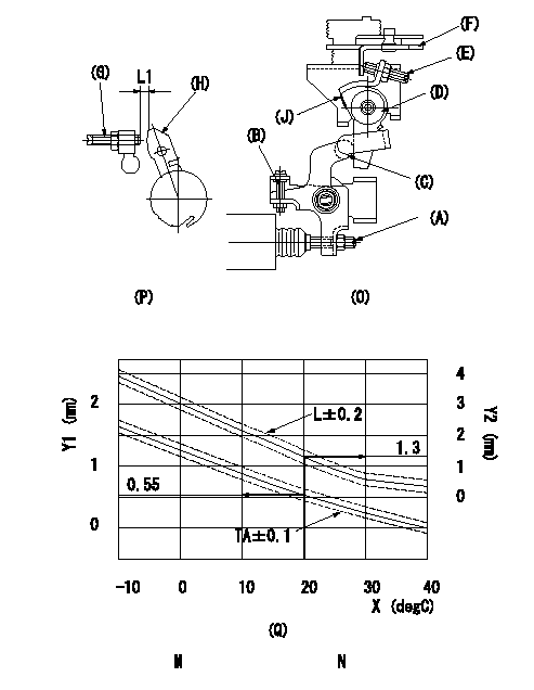
Adjustment of the W-CSD
1. Timer advance adjustment (refer to Fig 1 [O], 3 [Q]).
(1)Determine the timer advance angle from the graph in Fig. 3 (Q).
(2)(1) Adjust with the screw (A) so that the timer advance angle determined in the item (1) is obtained.
2. Setting the intermediate lever position (refer to fig 1 and fig 2)
(1)Insert a block gauge L1 between the idle set screw (G) and the lever (H).
(2)When the intermediate lever (D) is perpendicular, fix it so that it contacts the control lever (F).
(3)Align lever (D) perpendicular to the aligning mark (J).
3. W-CSD lever adjustment [refer to fig 1 (O) and fig 2 (P)]
(1)Insert a block gauge L2 determined from the graph (L-t) in the figure 3 (Q) between the idling set screw (G) and the lever (H).
(2)Adjust screw (B) so that the W-CSD lever (C)'s roller contacts the intermediate lever (D) and fix using the nut.
The temperature of the wax at adjustment must not exceed a.
Note:
When inserting the block gauge, separate lever (C) and (D) using screw (B) to prevent excessive force on the lever.
X:Temperature t (deg C)
Y1:Timer stroke TA (mm)
Y2:Control lever L dimension (mm)
M:Graph TA-t:
-10 <= t (deg C) <= 20: TA = -0.0367t + 1.284
20 <= t (deg C) <= 40: TA = -0.0275t + 1.1
N:Graph L-t
-10<= t (deg C) <= 20: L = -0.0867t + 3.03
20 <= t (deg C) <= 60: L = -0.075 t + 2.8
30 <= t (deg C) <= 40: L = -0.02t + 1.15
----------
L1=1.3+-0.05mm L2=L1+-0.05mm a=30degC
----------
L1=1.3+-0.05mm
----------
L1=1.3+-0.05mm L2=L1+-0.05mm a=30degC
----------
L1=1.3+-0.05mm
Information:
Aftermarket deviceA device or accessory installed by the customer after the vehicle is delivered. Air-To-Air Aftercooler (ATAAC)A means of cooling intake air after the turbocharger, using ambient air for cooling. The intake air is passed through an aftercooler (heat exchanger) mounted in front of the radiator before going to the intake manifold. Alternating Current (AC)The type of current where the direction of current flow changes (alternates) regularly and constantly. American Wire Gauge (AWG)A measure of the diameter (and therefore the current carrying ability) of electrical wire. The smaller the AWG number, the larger the wire. Before Top Dead Center (BTDC) or Before Top Center (BTC)The 180° of crankshaft rotation before the piston reaches Top Dead Center (normal direction of rotation). Boost Pressure SensorThis sensor measures inlet manifold air pressure and sends a signal to the ECM.. Bypass CircuitA circuit, usually temporary, to substitute for an existing circuit, typically for test purposes. CalibrationAs used here, is an electronic adjustment of a sensor signal. CodeSee Diagnostic Code. Customer Specified ParameterA Parameter that can be changed and whose value is set by the customer. Protected by Customer Passwords. Data LinkAn electrical connection for communication with other microprocessor based devices that are compatible with SAE Standard J1708/J1587 such as, electronic dashboards and maintenance systems. The Data Link is also the communication medium used for programming and troubleshooting with Caterpillar service tools. Desired RPMAn input to the electronic governor within the ECM. The electronic governor uses inputs from the Throttle Position Sensor, Engine Speed Sensor, and Customer Parameters to determine "Desired RPM". Desired Timing Advance ("Des Timing Adv" on ECAP)The injection timing advance calculated by the ECM as required to meet emission and performance specifications. Diagnostic CodeSometimes referred to as a "fault code", it is an indication of a problem or event in the 3176 System. Diagnostic LampSometimes referred to as the "check engine light", it is used to warn the operator of the presence of an active diagnostic code. Digital Diagnostic Tool (DDT)A Caterpillar Electronic Service Tool used for programming and diagnosing of the 3176 System. Direct CurrentThe type of current where the direction of current flow is consistently in one direction only. Duty CycleSee Pulse Width Modulation. Electronic Control Analyzer and Programmer (ECAP)A Caterpillar Electronic Service Tool used for programming and diagnosing a variety of electronic controls. An ECAP is needed for advanced diagnostic and programming functions not possible with a DDT. Electronic Control Module (ECM)The engine control computer that provides power to the 3176 electronics, monitors 3176 inputs and acts as a governor to control engine rpm. Electronic Engine Control (3176)The complete electronic system that monitors and controls engine operation under all conditions. Electronically Controlled Unit InjectorThe injection pump which is a mechanically actuated, electronically controlled unit injector combining the pumping, electronic fuel metering and injecting elements in a single unit. Engine Speed/Timing SensorProvides a Pulse Width Modulated Signal to the ECM, which the ECM interprets as crankshaft position and engine speed. Estimated Dynamic TimingThe ECM's estimate of