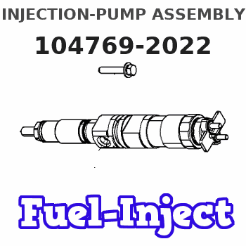
Information injection-pump assembly
ZEXEL
104769-2022
1047692022
Rating:
Cross reference number
ZEXEL
104769-2022
1047692022
Zexel num
Bosch num
Firm num
Name
Calibration Data:
Adjustment conditions
Test oil
1404 Test oil ISO4113orSAEJ967d
1404 Test oil ISO4113orSAEJ967d
Test oil temperature
degC
45
45
50
Nozzle
105000-2010
Bosch type code
NP-DN12SD12TT
Nozzle holder
105780-2080
Opening pressure
MPa
14.7
14.7
15.19
Opening pressure
kgf/cm2
150
150
155
Injection pipe
Inside diameter - outside diameter - length (mm) mm 2-6-840
Inside diameter - outside diameter - length (mm) mm 2-6-840
Transfer pump pressure
kPa
20
20
20
Transfer pump pressure
kgf/cm2
0.2
0.2
0.2
Direction of rotation (viewed from drive side)
Right R
Right R
Injection timing adjustment
Pump speed
r/min
900
900
900
Average injection quantity
mm3/st.
29.5
29
30
Difference in delivery
mm3/st.
2.5
Basic
*
Injection timing adjustment_02
Pump speed
r/min
2600
2600
2600
Average injection quantity
mm3/st.
18.5
15
22
Injection timing adjustment_03
Pump speed
r/min
2300
2300
2300
Average injection quantity
mm3/st.
30.45
28.1
32.8
Injection timing adjustment_04
Pump speed
r/min
900
900
900
Average injection quantity
mm3/st.
29.5
28.5
30.5
Injection timing adjustment_05
Pump speed
r/min
600
600
600
Average injection quantity
mm3/st.
28.8
26.6
31
Injection quantity adjustment
Pump speed
r/min
2600
2600
2600
Average injection quantity
mm3/st.
18.5
15.5
21.5
Basic
*
Injection quantity adjustment_02
Pump speed
r/min
2800
2800
2800
Average injection quantity
mm3/st.
5
Governor adjustment
Pump speed
r/min
350
350
350
Average injection quantity
mm3/st.
7.8
6.3
9.3
Basic
*
Governor adjustment_02
Pump speed
r/min
350
350
350
Average injection quantity
mm3/st.
7.8
5.8
9.8
Difference in delivery
mm3/st.
2.5
Governor adjustment_03
Pump speed
r/min
500
500
500
Average injection quantity
mm3/st.
4
Boost compensator adjustment
Pump speed
r/min
900
900
900
Average injection quantity
mm3/st.
9.5
4.5
14.5
Remarks
From idle
From idle
Timer adjustment
Pump speed
r/min
100
100
100
Average injection quantity
mm3/st.
44.8
40.8
48.8
Basic
*
Remarks
Refer to additional devices.
Refer to additional devices.
Speed control lever angle
Pump speed
r/min
350
350
350
Average injection quantity
mm3/st.
0
0
0
Remarks
Magnet OFF
Magnet OFF
0000000901
Pump speed
r/min
1000
1000
1000
Overflow quantity
cm3/min
450
318
582
Stop lever angle
Pump speed
r/min
900
900
900
Pressure
kPa
372.5
343
402
Pressure
kgf/cm2
3.8
3.5
4.1
Basic
*
Stop lever angle_02
Pump speed
r/min
900
900
900
Pressure
kPa
372.5
333
412
Pressure
kgf/cm2
3.8
3.4
4.2
Stop lever angle_03
Pump speed
r/min
1800
1800
1800
Pressure
kPa
588.5
549
628
Pressure
kgf/cm2
6
5.6
6.4
Stop lever angle_04
Pump speed
r/min
2500
2500
2500
Pressure
kPa
735.5
696
775
Pressure
kgf/cm2
7.5
7.1
7.9
0000001101
Pump speed
r/min
900
900
900
Timer stroke
mm
2.3
2
2.6
Basic
*
_02
Pump speed
r/min
900
900
900
Timer stroke
mm
2.3
1.9
2.7
_03
Pump speed
r/min
1200
1200
1200
Timer stroke
mm
4.2
3.6
4.8
_04
Pump speed
r/min
2500
2500
2500
Timer stroke
mm
8.55
8.1
9
0000001201
Max. applied voltage
V
8
8
8
Test voltage
V
13
12
14
0000001401
Pump speed
r/min
900
900
900
Average injection quantity
mm3/st.
9
8
10
Timer stroke variation dT
mm
0.5
0.2
0.8
Basic
*
Timing setting
K dimension
mm
3.3
3.2
3.4
KF dimension
mm
6.64
6.54
6.74
MS dimension
mm
1.8
1.7
1.9
Control lever angle alpha
deg.
25
21
29
Control lever angle beta
deg.
44
39
49
Control lever angle gamma
Partial lever position deg. 11 10.5 11.5
Partial lever position deg. 11 10.5 11.5
Test data Ex:
0000001801 STARTING I/Q ADJUSTMENT
Starting injection quantity adjustment
Adjust adjusting bolt so that the starting injection quantity is within the standard.
Fix using nut.
----------
----------
----------
----------
0000001901 W-CSD ADJUSTMENT
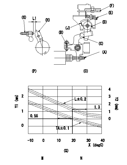
Adjustment of the W-CSD
1. Timer advance adjustment (refer to Fig 1 [O], 3 [Q]).
(1)Determine the timer advance angle from the graph in Fig. 3 (Q).
(2)(1) Adjust with the screw (A) so that the timer advance angle determined in the item (1) is obtained.
2. Setting the intermediate lever position (refer to fig 1 and fig 2)
(1)Insert a block gauge L1 between the idle set screw (G) and the lever (H).
(2)When the intermediate lever (D) is perpendicular, fix it so that it contacts the control lever (F).
(3)Align lever (D) perpendicular to the aligning mark (J).
3. W-CSD lever adjustment [refer to fig 1 (O) and fig 2 (P)]
(1)Insert a block gauge L2 determined from the graph (L-t) in the figure 3 (Q) between the idling set screw (G) and the lever (H).
(2)Adjust screw (B) so that the W-CSD lever (C)'s roller contacts the intermediate lever (D) and fix using the nut.
The temperature of the wax at adjustment must not exceed a.
Note:
When inserting the block gauge, separate lever (C) and (D) using screw (B) to prevent excessive force on the lever.
X:Temperature t (deg C)
Y1:Timer stroke TA (mm)
Y2:Control lever L dimension (mm)
M:Graph TA-t:
-10 <= t (deg C) <= 20: TA = -0.0367t + 1.284
20 <= t (deg C) <= 40: TA = -0.0275t + 1.1
N:Graph L-t
-10<= t (deg C) <= 20: L = -0.0867t + 3.03
20 <= t (deg C) <= 60: L = -0.075 t + 2.8
30 <= t (deg C) <= 40: L = -0.02t + 1.15
----------
L1=1.3+-0.05mm L2=L1+-0.05mm a=30degC
----------
L1=1.3+-0.05mm
----------
L1=1.3+-0.05mm L2=L1+-0.05mm a=30degC
----------
L1=1.3+-0.05mm
Information:
P-102: Engine Cranks But Will Not Start
Probable root causes:* Electrical power supply to the ECM.* Electrical connections to the fuel injectors.* Fuel supply* Engine Speed/Timing Signal* ECM or Personality Module failure.* Combustion problemPerform the following tests in order:1. P-210: Electrical Power Supply Test.2. If ECAP/DDT does not communicate with ECM, refer to P-120: ECAP/DDT Will Not Communicate With 3176 System, in this manual.3. Check that Fuel Injector Connector (J5/P5) is installed and oriented correctly.4. Check Fuel Pressure. Also, check that fuel system is primed and that fuel supply and return lines are not restricted. In temperatures below 0° C (32° F), check for congealed fuel (wax).5. P-221: Engine Speed/Timing Signal Test. Also be sure the timing reference ring is installed correctly (if the ring was installed backward during reassembly, the engine will not start).6. Check for combustion problems (too cold or mechanical problem).P-103: Engine Misfires, Runs Rough Or Is Unstable
If the problem is intermittent and cannot be re-created, refer to P-111: Intermittent Low Power Or Power Cutouts.If the problem is consistent and can be re-created, continue with this procedure. Probable root causes: If the problem only occurs under certain conditions (high rpm, full load, etc.) test the engine under those conditions. Troubleshooting the symptoms under other conditions can give misleading results.* Three cylinder cutout* Individual cylinder malfunction* Throttle position signal* Fuel supply - high pressure- low pressure- air in fuel- poor quality fuel* Air inlet restriction* Exhaust restrictionPerform the following tests in order:1. Verify that the complaint is not about the normal operation of the three-cylinder cutout feature.2. Isolate misfiring cylinder(s). Refer to P-222: Isolating Misfiring Cylinders, in this manual.3. Check throttle linkage adjustment. Refer to P-303: Throttle Position Sensor Adjustment, in this manual.4. Check Throttle Position Sensor. Refer to P-211: Throttle Position Sensor Test, in this manual.5. Check fuel quality. Refer to the Truck Performance Diagnostic Guide, Form No. SEBD0808.6. Inspect fuel system and check fuel pressure. Refer to 3176 Vehicular Diesel Engine, Form No. SENR4964, for Systems Operation, Testing & Adjusting.7. Check for air in fuel.8. Check for restrictions in the air inlet and exhaust systems. Refer to 3176 Vehicular Diesel Engine, Form No. SENR4964, for Systems Operation, Testing & Adjusting.P-104: Low Power/Poor Or No Response To Throttle
Probable root causes:* Active diagnostic codes* Customer Specified Parameters (normal operation)* Throttle position signal* Boost pressure signal* Fuel supply* Air inlet or exhaust restrictions* Inlet air system leaksPerform the following tests in order:1. Troubleshoot any ACTIVE diagnostic codes. * Codes 25 or 42 limit power or rpm or both* Code 32 limits engine speed to low idle* Code 56 may limit engine speed to low idle, depending on which parameter caused the code to be generated2. Verify that complaint is not normal (programmed parameter) operation.3. Verify that engine has shifted out of Cold Mode4. P-211: Throttle Position Sensor Test4. P-225: Boost Pressure Sensor Test5. Inspect fuel system components and check for correct fuel pressure.6. Check the air inlet and exhaust systems for restrictions.P-110: Intermittent Engine Shutdowns
Use this procedure ONLY