Information injection-pump assembly
ZEXEL
104769-2020
1047692020
Rating:
Cross reference number
ZEXEL
104769-2020
1047692020
Zexel num
Bosch num
Firm num
Name
Calibration Data:
Adjustment conditions
Test oil
1404 Test oil ISO4113orSAEJ967d
1404 Test oil ISO4113orSAEJ967d
Test oil temperature
degC
45
45
50
Nozzle
105000-2010
Bosch type code
NP-DN12SD12TT
Nozzle holder
105780-2080
Opening pressure
MPa
14.7
14.7
15.19
Opening pressure
kgf/cm2
150
150
155
Injection pipe
Inside diameter - outside diameter - length (mm) mm 2-6-840
Inside diameter - outside diameter - length (mm) mm 2-6-840
Transfer pump pressure
kPa
20
20
20
Transfer pump pressure
kgf/cm2
0.2
0.2
0.2
Direction of rotation (viewed from drive side)
Right R
Right R
Injection timing adjustment
Pump speed
r/min
1200
1200
1200
Average injection quantity
mm3/st.
29.6
29.1
30.1
Difference in delivery
mm3/st.
2.5
Basic
*
Injection timing adjustment_02
Pump speed
r/min
2700
2700
2700
Average injection quantity
mm3/st.
12.6
9.1
16.1
Injection timing adjustment_03
Pump speed
r/min
2300
2300
2300
Average injection quantity
mm3/st.
27.5
25.5
29.5
Injection timing adjustment_04
Pump speed
r/min
1200
1200
1200
Average injection quantity
mm3/st.
29.6
28.6
30.6
Injection timing adjustment_05
Pump speed
r/min
600
600
600
Average injection quantity
mm3/st.
27.4
25.4
29.4
Injection quantity adjustment
Pump speed
r/min
2700
2700
2700
Average injection quantity
mm3/st.
12.6
9.6
15.6
Basic
*
Injection quantity adjustment_02
Pump speed
r/min
2800
2800
2800
Average injection quantity
mm3/st.
5
Governor adjustment
Pump speed
r/min
350
350
350
Average injection quantity
mm3/st.
7.8
6.3
9.3
Difference in delivery
mm3/st.
3
Basic
*
Governor adjustment_02
Pump speed
r/min
350
350
350
Average injection quantity
mm3/st.
7.8
5.8
9.8
Governor adjustment_03
Pump speed
r/min
500
500
500
Average injection quantity
mm3/st.
4
Boost compensator adjustment
Pump speed
r/min
900
900
900
Average injection quantity
mm3/st.
9.5
4.5
14.5
Remarks
From idle
From idle
Timer adjustment
Pump speed
r/min
100
100
100
Average injection quantity
mm3/st.
44.8
40.8
48.8
Basic
*
Remarks
Refer to additional devices.
Refer to additional devices.
Speed control lever angle
Pump speed
r/min
350
350
350
Average injection quantity
mm3/st.
0
0
0
Remarks
Magnet OFF
Magnet OFF
0000000901
Pump speed
r/min
1000
1000
1000
Overflow quantity
cm3/min
450
318
582
Stop lever angle
Pump speed
r/min
1800
1800
1800
Pressure
kPa
588.5
559
618
Pressure
kgf/cm2
6
5.7
6.3
Basic
*
Stop lever angle_02
Pump speed
r/min
800
800
800
Pressure
kPa
363
324
402
Pressure
kgf/cm2
3.7
3.3
4.1
Stop lever angle_03
Pump speed
r/min
1800
1800
1800
Pressure
kPa
588.5
549
628
Pressure
kgf/cm2
6
5.6
6.4
Stop lever angle_04
Pump speed
r/min
2500
2500
2500
Pressure
kPa
735.5
696
775
Pressure
kgf/cm2
7.5
7.1
7.9
0000001101
Pump speed
r/min
1200
1200
1200
Timer stroke
mm
3.4
3.1
3.7
Basic
*
_02
Pump speed
r/min
900
900
900
Timer stroke
mm
1.8
1.2
2.4
_03
Pump speed
r/min
1200
1200
1200
Timer stroke
mm
3.4
3
3.8
_04
Pump speed
r/min
2500
2500
2500
Timer stroke
mm
8.15
7.7
8.6
0000001201
Max. applied voltage
V
8
8
8
Test voltage
V
13
12
14
0000001401
Pump speed
r/min
1200
1200
1200
Average injection quantity
mm3/st.
10
9
11
Timer stroke variation dT
mm
0.5
0.2
0.8
Basic
*
_02
Pump speed
r/min
1200
1200
1200
Average injection quantity
mm3/st.
10
8.5
11.5
Timer stroke variation dT
mm
0.5
0.1
0.9
Timing setting
K dimension
mm
3.3
3.2
3.4
KF dimension
mm
6.64
6.54
6.74
MS dimension
mm
1.8
1.7
1.9
Control lever angle alpha
deg.
25
21
29
Control lever angle beta
deg.
44
39
49
Control lever angle gamma
Partial lever position deg. 11 10.5 11.5
Partial lever position deg. 11 10.5 11.5
Test data Ex:
0000001801 STARTING I/Q ADJUSTMENT
Starting injection quantity adjustment
Adjust adjusting bolt so that the starting injection quantity is within the standard.
Fix using nut.
----------
----------
----------
----------
0000001901 W-CSD ADJUSTMENT
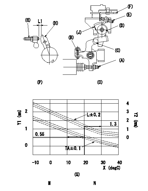
Adjustment of the W-CSD
1. Timer advance adjustment (refer to Fig 1 [O], 3 [Q]).
(1)Determine the timer advance angle from the graph in Fig. 3 (Q).
(2)(1) Adjust with the screw (A) so that the timer advance angle determined in the item (1) is obtained.
2. Setting the intermediate lever position (refer to fig 1 and fig 2)
(1)Insert a block gauge L1 between the idle set screw (G) and the lever (H).
(2)When the intermediate lever (D) is perpendicular, fix it so that it contacts the control lever (F).
(3)Align lever (D) perpendicular to the aligning mark (J).
3. W-CSD lever adjustment [refer to fig 1 (O) and fig 2 (P)]
(1)Insert a block gauge L2 determined from the graph (L-t) in the figure 3 (Q) between the idling set screw (G) and the lever (H).
(2)Adjust screw (B) so that the W-CSD lever (C)'s roller contacts the intermediate lever (D) and fix using the nut.
The temperature of the wax at adjustment must not exceed a.
Note:
When inserting the block gauge, separate lever (C) and (D) using screw (B) to prevent excessive force on the lever.
X:Temperature t (deg C)
Y1:Timer stroke TA (mm)
Y2:Control lever L dimension (mm)
M:Graph TA-t:
-10 <= t (deg C) <= 20: TA = -0.0367t + 1.284
20 <= t (deg C) <= 40: TA = -0.0275t + 1.1
N:Graph L-t
-10<= t (deg C) <= 20: L = -0.0867t + 3.03
20 <= t (deg C) <= 60: L = -0.075 t + 2.8
30 <= t (deg C) <= 40: L = -0.02t + 1.15
----------
L1=1.3+-0.05mm L2=L1+-0.05mm a=30degC
----------
L1=1.3+-0.05mm
----------
L1=1.3+-0.05mm L2=L1+-0.05mm a=30degC
----------
L1=1.3+-0.05mm
Information:
Customer Specified Parameters
Customer Specified Parameters allow a customer to restrict how a operator operates the vehicle. Some parameters may affect engine operation in ways that the uninformed operator does not expect. These parameters may lead to power and/or performance complaints, even when the engine is operating to specifications. If the NEXG4512 Customer Parameter Configuration Aid, Service Program Module (Optional Electronic Service Tool) is installed in an ECAP equipped with the 8C9700 Rechargeable Portable Printer, a list of Customer Specified Parameters can be read from the ECM and printed out.Customer parameters may be changed repeatedly as a customer changes his operation. Customer Passwords are required to change these parameters.The following is a brief description of the Customer Specified Parameters. Along with each, are the minimum and maximum values for the parameter and the default value. If a feature is not used, the parameter should be programmed to the default value.Engine Parameters
Rating Number:Number of rating within the horsepower family. The personality module defines the horsepower family (such as 325 hp). This number defines which rating is used (such as 325 hp at 1900 rpm or 325 hp at 2100 rpm) within the family. Top Engine Limit (TEL):Maximum engine rpm when the engine is under load. The engine will still achieve rated rpm under no load.Minimum ... Map (Rating) DependentMaximum ... Rated rpm + 20 rpmDefault ... Rated rpm + 20 rpm Top engine limiting with the 3176 has no governor overrun (it is an isochronous setting with no droop). Low Idle RPM:Minimum engine rpm.Minimum ... 600 rpmMaximum ... 750 rpmDefault ... 700 rpm Vehicle ID:Identification of vehicle assigned by customer. Used only for customer reference; not used by the ECM.Factory Passwords
Factory Passwords are required to perform any one of these four functions:1. Program a new ECM. When an ECM is replaced, the System Configuration Parameters must be programmed into the new ECM. These parameters are protected by Factory Passwords.2. Rerate the engine to another engine family. This requires changing the Personality Module Code, which is protected by Factory Passwords.3. Read Customer Passwords. If the owner forgets his Customer Passwords, he will not be able to program Customer Specified Parameters. Using factory passwords, one can read Customer Passwords, then use those Customer Passwords to program Customer Specified Parameters.4. Clear certain diagnostic codes. Only Diagnostic Code 35 (Engine Overspeed) requires Factory Passwords to clear once it is LOGGED. Clearing certain other codes requires Customer Passwords. The majority of LOGGED diagnostic codes require no passwords to clear.Factory Passwords are controlled by Caterpillar and may only be obtained by authorized Caterpillar Dealers. Since factory passwords contain alphabetic characters, only the ECAP may perform these functions.To obtain factory passwords, proceed as if you already had the password. At some point, if factory passwords are truly needed, the ECAP will request factory passwords and will provide most of the information required to obtain the password on the ECAP screen.Customer Passwords
Customer Passwords are required to change ANY Customer Parameter. Customer Specified Parameters are those