Information injection-pump assembly
BOSCH
9 460 614 763
9460614763
ZEXEL
104761-4330
1047614330
NISSAN-DIESEL
16700WJ103
16700wj103

Rating:
Cross reference number
BOSCH
9 460 614 763
9460614763
ZEXEL
104761-4330
1047614330
NISSAN-DIESEL
16700WJ103
16700wj103
Zexel num
Bosch num
Firm num
Name
104761-4330
9 460 614 763
16700WJ103 NISSAN-DIESEL
INJECTION-PUMP ASSEMBLY
TD42T K
TD42T K
Calibration Data:
Adjustment conditions
Test oil
1404 Test oil ISO4113orSAEJ967d
1404 Test oil ISO4113orSAEJ967d
Test oil temperature
degC
45
45
50
Nozzle
105780-0060
Bosch type code
NP-DN0SD1510
Nozzle holder
105780-2150
Opening pressure
MPa
13
13
13.3
Opening pressure
kgf/cm2
133
133
136
Injection pipe
157805-7320
Injection pipe
Inside diameter - outside diameter - length (mm) mm 2-6-450
Inside diameter - outside diameter - length (mm) mm 2-6-450
Joint assembly
157641-4720
Tube assembly
157641-4020
Transfer pump pressure
kPa
20
20
20
Transfer pump pressure
kgf/cm2
0.2
0.2
0.2
Direction of rotation (viewed from drive side)
Right R
Right R
Injection timing adjustment
Pump speed
r/min
500
500
500
Boost pressure
kPa
0
0
0
Boost pressure
kgf/cm2
0
0
0
Boost pressure
mmHg
0
0
0
Average injection quantity
mm3/st.
48.1
47.6
48.6
Basic
*
Oil temperature
degC
48
46
50
Remarks
NA
NA
Injection timing adjustment_02
Pump speed
r/min
700
700
700
Boost pressure
kPa
26.7
25.4
28
Boost pressure
kgf/cm2
0.27
0.256
0.284
Boost pressure
mmHg
200
190
210
Average injection quantity
mm3/st.
57.3
56.8
57.8
Basic
*
Oil temperature
degC
50
48
52
Remarks
CBS
CBS
Injection timing adjustment_03
Pump speed
r/min
1000
1000
1000
Boost pressure
kPa
53.3
52
54.6
Boost pressure
kgf/cm2
0.54
0.526
0.554
Boost pressure
mmHg
400
390
410
Average injection quantity
mm3/st.
59.7
59.2
60.2
Difference in delivery
mm3/st.
4.5
Basic
*
Oil temperature
degC
50
48
52
Remarks
Full
Full
Injection timing adjustment_04
Pump speed
r/min
500
500
500
Boost pressure
kPa
0
0
0
Boost pressure
kgf/cm2
0
0
0
Boost pressure
mmHg
0
0
0
Average injection quantity
mm3/st.
48.1
47.1
49.1
Basic
*
Oil temperature
degC
48
46
50
Remarks
NA
NA
Injection timing adjustment_05
Pump speed
r/min
700
700
700
Boost pressure
kPa
26.7
25.4
28
Boost pressure
kgf/cm2
0.27
0.256
0.284
Boost pressure
mmHg
200
190
210
Average injection quantity
mm3/st.
57.3
56.3
58.3
Basic
*
Oil temperature
degC
48
46
50
Remarks
CBS
CBS
Injection timing adjustment_06
Pump speed
r/min
1000
1000
1000
Boost pressure
kPa
53.3
52
54.6
Boost pressure
kgf/cm2
0.54
0.526
0.554
Boost pressure
mmHg
400
390
410
Average injection quantity
mm3/st.
59.7
58.7
60.7
Difference in delivery
mm3/st.
5
Basic
*
Oil temperature
degC
50
48
52
Remarks
Full
Full
Injection timing adjustment_07
Pump speed
r/min
1250
1250
1250
Boost pressure
kPa
53.3
52
54.6
Boost pressure
kgf/cm2
0.54
0.526
0.554
Boost pressure
mmHg
400
390
410
Average injection quantity
mm3/st.
61.4
58.4
64.4
Oil temperature
degC
50
48
52
Injection timing adjustment_08
Pump speed
r/min
1800
1800
1800
Boost pressure
kPa
53.3
52
54.6
Boost pressure
kgf/cm2
0.54
0.526
0.554
Boost pressure
mmHg
400
390
410
Average injection quantity
mm3/st.
56
52
60
Oil temperature
degC
50
48
52
Injection quantity adjustment
Pump speed
r/min
2300
2300
2300
Boost pressure
kPa
53.3
52
54.6
Boost pressure
kgf/cm2
0.54
0.526
0.554
Boost pressure
mmHg
400
390
410
Average injection quantity
mm3/st.
17.8
15.8
19.8
Basic
*
Oil temperature
degC
52
50
54
Injection quantity adjustment_02
Pump speed
r/min
2500
2500
2500
Boost pressure
kPa
53.3
52
54.6
Boost pressure
kgf/cm2
0.54
0.526
0.554
Boost pressure
mmHg
400
390
410
Average injection quantity
mm3/st.
5
Oil temperature
degC
55
52
58
Injection quantity adjustment_03
Pump speed
r/min
2300
2300
2300
Boost pressure
kPa
53.3
52
54.6
Boost pressure
kgf/cm2
0.54
0.526
0.554
Boost pressure
mmHg
400
390
410
Average injection quantity
mm3/st.
17.8
15.3
20.3
Basic
*
Oil temperature
degC
52
50
54
Governor adjustment
Pump speed
r/min
350
350
350
Boost pressure
kPa
0
0
0
Boost pressure
kgf/cm2
0
0
0
Boost pressure
mmHg
0
0
0
Average injection quantity
mm3/st.
7.2
5.2
9.2
Difference in delivery
mm3/st.
2
Basic
*
Oil temperature
degC
48
46
50
Governor adjustment_02
Pump speed
r/min
350
350
350
Boost pressure
kPa
0
0
0
Boost pressure
kgf/cm2
0
0
0
Boost pressure
mmHg
0
0
0
Average injection quantity
mm3/st.
7.2
4.7
9.7
Difference in delivery
mm3/st.
2.5
Basic
*
Oil temperature
degC
48
46
50
Timer adjustment
Pump speed
r/min
100
100
100
Boost pressure
kPa
0
0
0
Boost pressure
kgf/cm2
0
0
0
Boost pressure
mmHg
0
0
0
Average injection quantity
mm3/st.
61.5
51.5
81.5
Basic
*
Oil temperature
degC
48
46
50
Remarks
Full
Full
Timer adjustment_02
Pump speed
r/min
100
100
100
Boost pressure
kPa
0
0
0
Boost pressure
kgf/cm2
0
0
0
Boost pressure
mmHg
0
0
0
Average injection quantity
mm3/st.
61.5
51.5
81.5
Oil temperature
degC
48
46
50
Remarks
Full
Full
Speed control lever angle
Pump speed
r/min
350
350
350
Boost pressure
kPa
0
0
0
Boost pressure
kgf/cm2
0
0
0
Boost pressure
mmHg
0
0
0
Average injection quantity
mm3/st.
0
0
0
Oil temperature
degC
48
46
50
Remarks
Magnet OFF at idling position
Magnet OFF at idling position
Speed control lever angle_02
Pump speed
r/min
250
250
250
Boost pressure
kPa
0
0
0
Boost pressure
kgf/cm2
0
0
0
Boost pressure
mmHg
0
0
0
Average injection quantity
mm3/st.
5
Oil temperature
degC
48
46
50
Remarks
Magnet OFF at full-load position
Magnet OFF at full-load position
0000000901
Pump speed
r/min
1250
1250
1250
Boost pressure
kPa
53.3
52
54.6
Boost pressure
kgf/cm2
0.54
0.526
0.554
Boost pressure
mmHg
400
390
410
Overflow quantity
cm3/min
390
260
520
Oil temperature
degC
50
48
52
Stop lever angle
Pump speed
r/min
1250
1250
1250
Boost pressure
kPa
53.3
52
54.6
Boost pressure
kgf/cm2
0.54
0.526
0.554
Boost pressure
mmHg
400
390
410
Pressure
kPa
441
412
470
Pressure
kgf/cm2
4.5
4.2
4.8
Basic
*
Oil temperature
degC
50
48
52
Stop lever angle_02
Pump speed
r/min
1250
1250
1250
Boost pressure
kPa
53.3
52
54.6
Boost pressure
kgf/cm2
0.54
0.526
0.554
Boost pressure
mmHg
400
390
410
Pressure
kPa
441
402
480
Pressure
kgf/cm2
4.5
4.1
4.9
Basic
*
Oil temperature
degC
50
48
52
Stop lever angle_03
Pump speed
r/min
1700
1700
1700
Boost pressure
kPa
53.3
52
54.6
Boost pressure
kgf/cm2
0.54
0.526
0.554
Boost pressure
mmHg
400
390
410
Pressure
kPa
588
549
627
Pressure
kgf/cm2
6
5.6
6.4
Oil temperature
degC
50
48
52
0000001101
Pump speed
r/min
1250
1250
1250
Boost pressure
kPa
53.3
52
54.6
Boost pressure
kgf/cm2
0.54
0.526
0.554
Boost pressure
mmHg
400
390
410
Timer stroke
mm
3.1
2.9
3.3
Basic
*
Oil temperature
degC
50
48
52
_02
Pump speed
r/min
1000
1000
1000
Boost pressure
kPa
53.3
52
54.6
Boost pressure
kgf/cm2
0.54
0.526
0.554
Boost pressure
mmHg
400
390
410
Timer stroke
mm
2
1.5
2.5
Oil temperature
degC
50
48
52
_03
Pump speed
r/min
1250
1250
1250
Boost pressure
kPa
53.3
52
54.6
Boost pressure
kgf/cm2
0.54
0.526
0.554
Boost pressure
mmHg
400
390
410
Timer stroke
mm
3.1
2.8
3.4
Basic
*
Oil temperature
degC
50
48
52
_04
Pump speed
r/min
1700
1700
1700
Boost pressure
kPa
53.3
52
54.6
Boost pressure
kgf/cm2
0.54
0.526
0.554
Boost pressure
mmHg
400
390
410
Timer stroke
mm
5.3
4.8
5.8
Oil temperature
degC
50
48
52
_05
Pump speed
r/min
2150
2150
2150
Boost pressure
kPa
53.3
52
54.6
Boost pressure
kgf/cm2
0.54
0.526
0.554
Boost pressure
mmHg
400
390
410
Timer stroke
mm
7
6.5
7.4
Oil temperature
degC
52
50
54
0000001201
Max. applied voltage
V
16
16
16
Test voltage
V
25
24
26
0000001401
Pump speed
r/min
1250
1250
1250
Boost pressure
kPa
53.3
52
54.6
Boost pressure
kgf/cm2
0.54
0.526
0.554
Boost pressure
mmHg
400
390
410
Average injection quantity
mm3/st.
46
45.5
46.5
Timer stroke TA
mm
2.4
2.2
2.6
Timer stroke variation dT
mm
0.7
0.7
0.7
Basic
*
Oil temperature
degC
50
48
52
_02
Pump speed
r/min
1250
1250
1250
Boost pressure
kPa
53.3
52
54.6
Boost pressure
kgf/cm2
0.54
0.526
0.554
Boost pressure
mmHg
400
390
410
Average injection quantity
mm3/st.
46
45
47
Timer stroke TA
mm
2.4
2.2
2.6
Timer stroke variation dT
mm
0.7
0.7
0.7
Basic
*
Oil temperature
degC
50
48
52
_03
Pump speed
r/min
1250
1250
1250
Boost pressure
kPa
53.3
52
54.6
Boost pressure
kgf/cm2
0.54
0.526
0.554
Boost pressure
mmHg
400
390
410
Average injection quantity
mm3/st.
35
32.5
37.5
Timer stroke TA
mm
1.6
1.1
2.1
Timer stroke variation dT
mm
1.5
1.5
1.5
Oil temperature
degC
50
48
52
Timing setting
K dimension
mm
3.3
3.2
3.4
KF dimension
mm
6.76
6.66
6.86
MS dimension
mm
1.3
1.2
1.4
BCS stroke
mm
2.9
2.7
3.1
Pre-stroke
mm
0.1
0.08
0.12
Control lever angle alpha
deg.
55.5
51.5
59.5
Control lever angle beta
deg.
40
35
45
Test data Ex:
0000001801 POTENTIOMETER ADJUSTMENT
Potentiometer adjustment
1. Applied voltage: Vi
2. Boost pressure = P1kPa {P2 mmHg}
3. Set the control lever at the adjusting point. Position the dummy bolt against the lever and fix.
4. Assemble the potentiometer to obtain output voltage V1 (V) at the fixed position.
5. After mounting the potentiometer, remove the dummy bolt.
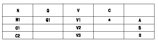
N:Pump speed
Q:Injection quantity
V:Output voltage
A:Performance standards
B:ON, OFF switch standard
C:Angle of the control lever
D:OFF-->ON
E:OFF-->ON
F:Adjusting point
C1:Idle
C2:Full-speed
----------
V1=5.04+-0.03V P1=53.3kPa P2=400mmHg Vi=10V
----------
N1=1080r/min Q1=48.9+-1.0cm3/1,000st V1=5.04+-0.03V V2=0.81+-0.6V V3=7.25+-0.75V a=-deg
----------
V1=5.04+-0.03V P1=53.3kPa P2=400mmHg Vi=10V
----------
N1=1080r/min Q1=48.9+-1.0cm3/1,000st V1=5.04+-0.03V V2=0.81+-0.6V V3=7.25+-0.75V a=-deg
Information:
Ultra Low Sulfur Diesel (ULSD) poses a greater static ignition hazard than earlier diesel formulations, with a higher sulfur content, which may result in a fire or explosion. Consult with your fuel or fuel system supplier for details on proper grounding and bonding practices.
Note: The removal of sulfur and other compounds in Ultra Low Sulfur Diesel (ULSD) fuel decreases the conductivity of ULSD and increases the ability of the fuel to store static charge. Refineries may have treated the fuel with a static dissipating additive. However, there are many factors that can reduce the effectiveness of the additive over time. Static charges can build up in ULSD fuel while the fuel is flowing through fuel delivery systems. Static electricity discharge when combustible vapors are present could result in a fire or explosion. Therefore, ensuring that the entire system used to refuel your machine (fuel supply tank, transfer pump, transfer hose, nozzle, and others) is properly grounded and bonded is important. Consult with your fuel or fuel system supplier to ensure that the delivery system is in compliance with fueling standards for proper grounding and bonding practices.The two basic types of distillate diesel fuel are No. 2 diesel fuel and No. 1 diesel fuel. No. 2 diesel fuel is the most commonly available summer grade diesel fuel. No. 1 diesel fuel is a winter grade diesel fuel. During the winter months fuel suppliers will typically blend No. 1 and No. 2 diesel fuel in various percentages to meet the historical low ambient temperature cold-flow needs for a given area or region. No. 2 diesel fuel is a heavier diesel fuel than No. 1 diesel fuel. In cold weather, heavier fuels can cause problems with fuel filters, fuel lines, fuel tanks, and fuel storage. Heavier diesel fuels such as No. 2 diesel fuel can be used in diesel engines that operate in cold temperatures with an appropriate amount of a well proven pour point depressant additive. For more information on fuels which include blends of No. 1 and No. 2 diesel fuel, consult your fuel supplier.When you use No. 2 diesel fuel or other heavier fuels, some of the fuel characteristics may interfere with successful cold-weather operation. Additional information about the characteristics of diesel fuel is available. This information contains a discussion on the modification to the characteristics of diesel fuel. There are several possible methods that can be used to compensate for the fuel qualities that may interfere with cold-weather operation. These methods include the use of starting aids, engine coolant heaters, fuel heaters, and de-icers. In addition, the manufacturer of the fuel can add cold flow improvers and/or blend No. 1 and No. 2 diesel in various percentages.Not all areas of the world classify diesel fuel using the No. 1 and No. 2 nomenclature described above. But, the basic principles of using additives and/or blending fuels of different densities to help compensate for the fuel qualities that may interfere with cold-weather operation are the same.Starting Aids
The use of
Have questions with 104761-4330?
Group cross 104761-4330 ZEXEL
Nissan-Diesel
104761-4330
9 460 614 763
16700WJ103
INJECTION-PUMP ASSEMBLY
TD42T
TD42T