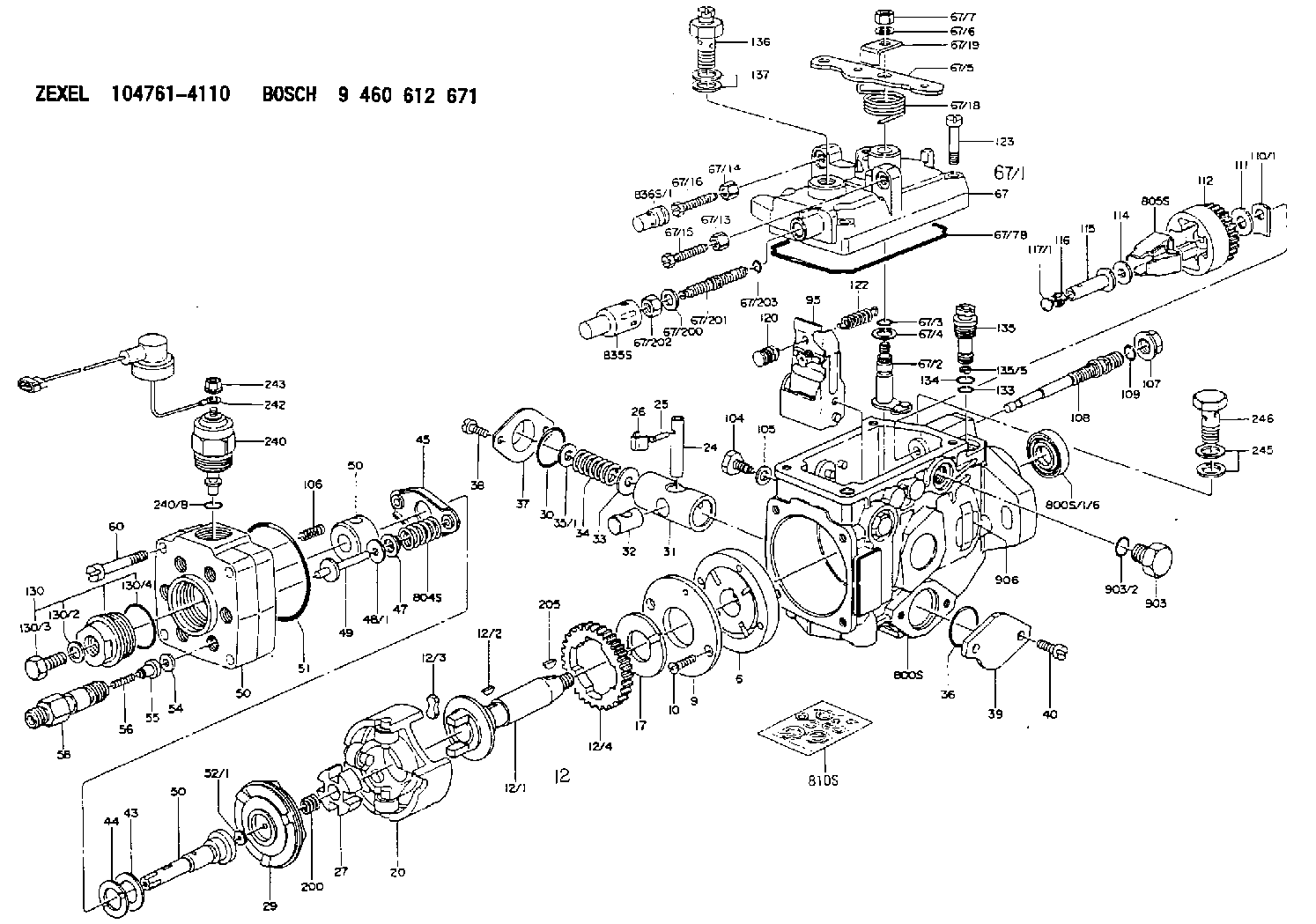
Information injection-pump assembly
BOSCH
9 460 612 671
9460612671
ZEXEL
104761-4110
1047614110

Rating:
Components :
| 0. | INJECTION-PUMP ASSEMBLY | 104761-4110 |
| 1. | _ | |
| 2. | FUEL INJECTION PUMP | 104661-4110 |
| 3. | NUMBER PLATE | 146950-3200 |
| 4. | _ | |
| 5. | CAPSULE | 146620-0120 |
| 6. | ADJUSTING DEVICE | |
| 7. | NOZZLE AND HOLDER ASSY | 105118-4160 |
| 8. | Nozzle and Holder | 6206-11-3100 |
| 9. | Open Pre:MPa(Kqf/cm2) | 19.6{200} |
| 10. | NOZZLE-HOLDER | 105048-3060 |
| 11. | NOZZLE | 105017-0140 |
Scheme ###:
| 1/6. | [1] | 146601-1100 | PACKING RING |
| 6. | [1] | 146100-0520 | SUPPLY PUMP |
| 9. | [1] | 146103-0000 | COVER |
| 10. | [2] | 139104-0000 | FLAT-HEAD SCREW |
| 12. | [1] | 146200-0320 | DRIVE SHAFT |
| 12/1. | [1] | 146200-0300 | DRIVE SHAFT |
| 12/2. | [1] | 146201-0000 | WOODRUFF KEY |
| 12/3. | [2] | 146202-0100 | DAMPER |
| 12/4. | [1] | 146203-0000 | TOOTHED GEAR |
| 17. | [1] | 146204-0000 | PLAIN WASHER |
| 20. | [1] | 146210-0020 | ROLLER SET |
| 24. | [1] | 146303-0000 | BEARING PIN |
| 25. | [1] | 146304-0000 | BEARING PIN |
| 26. | [1] | 146305-0000 | CLAMPING BAND |
| 27. | [1] | 146205-0000 | SLOTTED WASHER |
| 29. | [1] | 146221-0620 | CAM PLATE |
| 30. | [1] | 146600-0800 | O-RING |
| 31. | [1] | 146300-0200 | PUMP PLUNGER |
| 32. | [1] | 146301-0000 | SLIDING PIECE |
| 33. | [1] | 146603-0700 | SHIM D17.5&7.5T0.60 |
| 34. | [1] | 146302-4000 | COMPRESSION SPRING |
| 35/1. | [0] | 146603-0700 | SHIM D17.5&7.5T0.60 |
| 35/1. | [0] | 146603-0800 | SHIM D17.5&7.5T0.70 |
| 35/1. | [0] | 146603-0900 | SHIM D17.5&7.5T0.90 |
| 35/1. | [0] | 146603-1000 | SHIM D17.5&7.5T1.00 |
| 35/1. | [0] | 146603-1100 | SHIM D17.5&7.5T1.20 |
| 35/1. | [0] | 146603-3600 | SHIM D17.5&7.5T2.40 |
| 36. | [1] | 146600-0800 | O-RING |
| 37. | [1] | 146310-0700 | COVER |
| 38. | [2] | 146620-5000 | BLEEDER SCREW |
| 39. | [1] | 146310-0800 | COVER |
| 40. | [2] | 146620-5000 | BLEEDER SCREW |
| 43. | [1] | 146230-0000 | SHIM |
| 44. | [1] | 146230-0100 | PLAIN WASHER |
| 45. | [1] | 146231-0001 | SLOTTED WASHER |
| 47. | [2] | 146233-0000 | SLOTTED WASHER |
| 48/1. | [1] | 146603-0000 | SHIM D17.0&5.2T0.50 |
| 48/1. | [1] | 146603-0100 | SHIM D17.0&5.2T0.80 |
| 48/1. | [1] | 146603-0200 | SHIM D17.0&5.2T1.00 |
| 48/1. | [1] | 146603-0300 | SHIM D17.0&5.2T1.20 |
| 48/1. | [1] | 146603-0400 | SHIM D17.0&5.2T1.50 |
| 48/1. | [1] | 146603-0500 | SHIM D17.0&5.2T1.80 |
| 48/1. | [1] | 146603-0600 | SHIM D17.0&5.2T2.00 |
| 48/1. | [1] | 146690-1400 | SHIM D17&5.2T0.9 |
| 48/1. | [1] | 146690-1500 | SHIM D17&5.2T1.1 |
| 48/1. | [1] | 146690-1600 | SHIM D17&5.2T1.3 |
| 48/1. | [1] | 146690-1700 | SHIM D17&5.2T1.4 |
| 48/1. | [1] | 146690-1800 | SHIM D17&5.2T1.6 |
| 48/1. | [1] | 146690-1900 | SHIM D17&5.2T1.7 |
| 48/1. | [1] | 146690-5800 | SHIM |
| 48/1. | [1] | 146690-5900 | SHIM |
| 48/1. | [1] | 146690-6000 | SHIM |
| 48/1. | [1] | 146690-6100 | SHIM |
| 48/1. | [1] | 146690-6200 | SHIM |
| 48/1. | [1] | 146690-6300 | SHIM |
| 48/1. | [1] | 146690-6400 | SHIM |
| 48/1. | [1] | 146690-6500 | SHIM |
| 48/1. | [1] | 146690-6600 | SHIM |
| 48/1. | [1] | 146690-6700 | SHIM |
| 48/1. | [1] | 146690-6800 | SHIM |
| 48/1. | [1] | 146690-6900 | SHIM |
| 48/1. | [1] | 146690-7000 | SHIM |
| 48/1. | [1] | 146690-7100 | SHIM |
| 48/1. | [1] | 146690-7200 | SHIM |
| 48/1. | [1] | 146690-7300 | SHIM |
| 48/1. | [1] | 146690-7400 | SHIM |
| 48/1. | [1] | 146690-7500 | SHIM |
| 48/1. | [1] | 146690-7800 | SHIM |
| 49. | [2] | 146234-0020 | GUIDE PIN |
| 50. | [1] | 146406-0620 | HYDRAULIC HEAD |
| 50. | [1] | 146406-0620 | HYDRAULIC HEAD |
| 50. | [1] | 146406-0620 | HYDRAULIC HEAD |
| 51. | [1] | 146600-0000 | O-RING |
| 52/1. | [1] | 146420-0000 | SHIM D9.5&3.0T1.90 |
| 52/1. | [1] | 146420-0100 | SHIM D9.5&3.0T1.92 |
| 52/1. | [1] | 146420-0200 | SHIM D9.5&3.0T1.94 |
| 52/1. | [1] | 146420-0300 | SHIM D9.5&3.0T1.96 |
| 52/1. | [1] | 146420-0400 | SHIM D9.5&3.0T1.98 |
| 52/1. | [1] | 146420-0500 | SHIM D9.5&3.0T2.00 |
| 52/1. | [1] | 146420-0600 | SHIM D9.5&3.0T2.02 |
| 52/1. | [1] | 146420-0700 | SHIM D9.5&3.0T2.04 |
| 52/1. | [1] | 146420-0800 | SHIM D9.5&3.0T2.06 |
| 52/1. | [1] | 146420-0900 | SHIM D9.5&3.0T2.08 |
| 52/1. | [1] | 146420-1000 | SHIM D9.5&3.0T2.10 |
| 52/1. | [1] | 146420-1100 | SHIM D9.5&3.0T2.12 |
| 52/1. | [1] | 146420-1200 | SHIM D9.5&3.0T2.14 |
| 52/1. | [1] | 146420-1300 | SHIM D9.5&3.0T2.16 |
| 52/1. | [1] | 146420-1400 | SHIM D9.5&3.0T2.18 |
| 52/1. | [1] | 146420-1500 | SHIM D9.5&3.0T2.20 |
| 52/1. | [1] | 146420-1600 | SHIM D9.5&3.0T2.22 |
| 52/1. | [1] | 146420-1700 | SHIM D9.5&3.0T2.24 |
| 52/1. | [1] | 146420-1800 | SHIM D9.5&3.0T2.26 |
| 52/1. | [1] | 146420-1900 | SHIM D9.5&3.0T2.28 |
| 52/1. | [1] | 146420-2000 | SHIM D9.5&3.0T2.30 |
| 52/1. | [1] | 146420-2100 | SHIM D9.5&3.0T2.32 |
| 52/1. | [1] | 146420-2200 | SHIM D9.5&3.0T2.34 |
| 52/1. | [1] | 146420-2300 | SHIM D9.5&3.0T2.36 |
| 52/1. | [1] | 146420-2400 | SHIM D9.5&3.0T2.38 |
| 52/1. | [1] | 146420-2500 | SHIM D9.5&3.0T2.40 |
| 52/1. | [1] | 146420-2600 | SHIM D9.5&3.0T2.42 |
| 52/1. | [1] | 146420-2700 | SHIM D9.5&3.0T2.44 |
| 52/1. | [1] | 146420-2800 | SHIM D9.5&3.0T2.46 |
| 52/1. | [1] | 146420-2900 | SHIM D9.5&3.0T2.48 |
| 52/1. | [1] | 146420-3000 | SHIM D9.5&3.0T2.50 |
| 52/1. | [1] | 146420-3100 | SHIM D9.5&3.0T2.52 |
| 52/1. | [1] | 146420-3200 | SHIM D9.5&3.0T2.54 |
| 52/1. | [1] | 146420-3300 | SHIM D9.5&3.0T2.56 |
| 52/1. | [1] | 146420-3400 | SHIM D9.5&3.0T2.58 |
| 52/1. | [1] | 146420-3500 | SHIM D9.5&3.0T2.60 |
| 52/1. | [1] | 146420-3600 | SHIM D9.5&3.0T2.62 |
| 52/1. | [1] | 146420-3700 | SHIM D9.5&3.0T2.64 |
| 52/1. | [1] | 146420-3800 | SHIM D9.5&3.0T2.66 |
| 52/1. | [1] | 146420-3900 | SHIM D9.5&3.0T2.68 |
| 52/1. | [1] | 146420-4000 | SHIM D9.5&3.0T2.70 |
| 52/1. | [1] | 146420-4100 | SHIM D9.5&3.0T2.72 |
| 52/1. | [1] | 146420-4200 | SHIM D9.5&3.0T2.74 |
| 52/1. | [1] | 146420-4300 | SHIM D9.5&3.0T2.76 |
| 52/1. | [1] | 146420-4400 | SHIM D9.5&3.0T2.78 |
| 52/1. | [1] | 146420-4500 | SHIM D9.5&3.0T2.80 |
| 52/1. | [1] | 146420-4600 | SHIM D9.5&3.0T2.82 |
| 52/1. | [1] | 146420-4700 | SHIM D9.5&3.0T2.84 |
| 52/1. | [1] | 146420-4800 | SHIM D9.5&3.0T2.86 |
| 52/1. | [1] | 146420-4900 | SHIM D9.5&3.0T2.88 |
| 52/1. | [1] | 146420-5000 | SHIM D9.5&3.0T2.90 |
| 52/1. | [1] | 146420-5100 | SHIM D9.5&3.0T1.74 |
| 52/1. | [1] | 146420-5200 | SHIM D9.5&3.0T1.76 |
| 52/1. | [1] | 146420-5300 | SHIM D9.5&3.0T1.78 |
| 52/1. | [1] | 146420-5400 | SHIM D9.5&3.0T1.80 |
| 52/1. | [1] | 146420-5500 | SHIM D9.5&3.0T1.82 |
| 52/1. | [1] | 146420-5600 | SHIM D9.5&3.0T1.84 |
| 52/1. | [1] | 146420-5700 | SHIM D9.5&3.0T1.86 |
| 52/1. | [1] | 146420-5800 | SHIM D9.5&3.0T1.88 |
| 54. | [6] | 146433-0100 | GASKET D12&6.4T1.00 |
| 55. | [6] | 146430-0320 | DELIVERY-VALVE ASSEMBLY |
| 56. | [6] | 146432-0200 | COMPRESSION SPRING |
| 58. | [6] | 146440-0720 | FITTING |
| 60. | [4] | 139106-0100 | FLAT-HEAD SCREW |
| 67. | [1] | 146500-9421 | GOVERNOR COVER |
| 67/1. | [1] | 146505-5722 | GOVERNOR COVER |
| 67/2. | [1] | 146515-2520 | CONTROL SHAFT |
| 67/3. | [1] | 146600-0100 | O-RING |
| 67/4. | [1] | 139310-0200 | PLAIN WASHER |
| 67/5. | [1] | 146530-0000 | CONTROL LEVER |
| 67/5B. | [1] | 146530-0100 | CONTROL LEVER |
| 67/6. | [1] | 014110-6440 | LOCKING WASHER |
| 67/7. | [1] | 013020-6040 | UNION NUT M6P1H5 |
| 67/13. | [1] | 146621-1700 | UNION NUT |
| 67/14. | [1] | 146621-1700 | UNION NUT |
| 67/15. | [1] | 146526-2800 | BLEEDER SCREW |
| 67/16. | [1] | 146526-2800 | BLEEDER SCREW |
| 67/18. | [1] | 146587-2000 | COILED SPRING |
| 67/19. | [1] | 146541-0000 | ANGLE PIECE |
| 67/78. | [1] | 146600-4400 | SEAL RING |
| 67/200. | [1] | 139308-0300 | PLAIN WASHER |
| 67/201. | [1] | 146545-3400 | THREADED PIN L53.00 |
| 67/201B. | [1] | 146545-3500 | THREADED PIN L55.00 |
| 67/201C. | [1] | 146545-3600 | THREADED PIN L57.00 |
| 67/202. | [1] | 139208-0900 | UNION NUT |
| 67/203. | [1] | 146600-1200 | O-RING |
| 95. | [1] | 146561-1920 | FULCRUM LEVER |
| 104. | [2] | 146568-0200 | SLOTTED SPRING PIN |
| 105. | [2] | 026508-1140 | GASKET D11.4&8.2T1 |
| 106. | [2] | 146588-0500 | COILED SPRING |
| 107. | [1] | 146569-0300 | UNION NUT |
| 108. | [1] | 146570-0100 | GOVERNOR SHAFT |
| 109. | [1] | 146600-0400 | O-RING |
| 110/1. | [1] | 146571-0000 | SHIM D20.2&8.3T1.05 |
| 110/1. | [1] | 146571-0100 | SHIM D20.2&8.3T1.25 |
| 110/1. | [1] | 146571-0200 | SHIM D20.2&8.3T1.45 |
| 110/1. | [1] | 146571-0300 | SHIM D20.2&8.3T1.65 |
| 110/1. | [1] | 146571-0400 | SHIM D20.2&8.3T1.85 |
| 110/1. | [1] | 146571-0500 | SHIM D20.2&8.3T1.15 |
| 110/1. | [1] | 146571-0600 | SHIM D20.2&8.3T1.35 |
| 110/1. | [1] | 146571-0700 | SHIM D20.2&8.3T1.55 |
| 110/1. | [1] | 146571-0800 | SHIM D20.2&8.3T1.75 |
| 111. | [1] | 146602-0600 | PLAIN WASHER D20&8.4T1.40 |
| 112. | [1] | 146572-0020 | FLYWEIGHT ASSEMBLY |
| 114. | [1] | 146602-0500 | PLAIN WASHER D17&6.4T1.60 |
| 115. | [1] | 146575-2100 | SLIDING SLEEVE |
| 116. | [1] | 146576-0200 | CAP |
| 117/1. | [1] | 146577-0000 | PLUG L1.70 |
| 117/1. | [1] | 146577-0100 | PLUG L1.90 |
| 117/1. | [1] | 146577-0200 | PLUG L2.10 |
| 117/1. | [1] | 146577-0300 | PLUG L2.30 |
| 117/1. | [1] | 146577-0400 | PLUG L2.50 |
| 117/1. | [1] | 146577-0500 | PLUG L2.70 |
| 117/1. | [1] | 146577-0600 | PLUG L2.90 |
| 117/1. | [1] | 146577-0700 | PLUG L3.10 |
| 117/1. | [1] | 146577-0800 | PLUG L3.30 |
| 117/1. | [1] | 146577-0900 | PLUG L3.50 |
| 117/1. | [1] | 146577-1000 | PLUG L3.70 |
| 117/1. | [1] | 146577-1100 | PLUG L3.90 |
| 117/1. | [1] | 146577-1200 | PLUG L4.10 |
| 117/1. | [1] | 146577-1300 | PLUG L4.30 |
| 117/1. | [1] | 146577-1400 | PLUG L4.50 |
| 117/1. | [1] | 146577-1500 | PLUG L4.70 |
| 117/1. | [1] | 146577-1600 | PLUG L4.90 |
| 117/1. | [1] | 146577-1700 | PLUG L5.10 |
| 117/1. | [1] | 146577-5000 | PLUG L1.8 |
| 117/1. | [1] | 146577-5100 | PLUG L2.0 |
| 117/1. | [1] | 146577-5200 | PLUG L2.2 |
| 117/1. | [1] | 146577-5300 | PLUG L2.4 |
| 117/1. | [1] | 146577-5400 | PLUG L2.6 |
| 117/1. | [1] | 146577-5500 | PLUG L2.8 |
| 117/1. | [1] | 146577-5600 | PLUG L3.0 |
| 117/1. | [1] | 146577-5700 | PLUG L3.2 |
| 117/1. | [1] | 146577-5800 | PLUG L3.4 |
| 117/1. | [1] | 146577-5900 | PLUG L3.6 |
| 117/1. | [1] | 146577-6000 | PLUG L3.8 |
| 117/1. | [1] | 146577-6100 | PLUG L4.0 |
| 117/1. | [1] | 146577-6200 | PLUG L4.2 |
| 117/1. | [1] | 146577-6300 | PLUG L4.4 |
| 117/1. | [1] | 146577-6400 | PLUG L4.6 |
| 117/1. | [1] | 146577-6500 | PLUG L4.8 |
| 117/1. | [1] | 146577-6600 | PLUG L5.0 |
| 117/1. | [1] | 146877-0400 | PLUG |
| 117/1. | [1] | 146877-0500 | PLUG |
| 117/1. | [1] | 146877-0600 | PLUG |
| 117/1. | [1] | 146877-0700 | PLUG |
| 117/1. | [1] | 146877-4300 | PLUG |
| 117/1. | [1] | 146877-4400 | PLUG |
| 117/1. | [1] | 146877-4500 | PLUG |
| 117/1. | [1] | 146877-4600 | PLUG |
| 120. | [1] | 146579-5520 | RETAINING PIN |
| 122. | [1] | 146580-3000 | GOVERNOR SPRING |
| 123. | [4] | 139106-0200 | FLAT-HEAD SCREW |
| 130. | [1] | 146421-0020 | CAPSULE |
| 130/2. | [1] | 026508-1140 | GASKET D11.4&8.2T1 |
| 130/3. | [1] | 146422-0000 | BLEEDER SCREW |
| 130/4. | [1] | 146600-0500 | O-RING |
| 133. | [1] | 146600-0600 | O-RING |
| 134. | [1] | 146600-0700 | O-RING |
| 135. | [1] | 146110-1620 | CONTROL VALVE |
| 135/5. | [1] | 146114-0000 | SPRING WASHER |
| 136. | [1] | 146120-1020 | OVER FLOW VALVE |
| 137. | [2] | 029341-2140 | GASKET |
| 200. | [1] | 146206-0100 | COILED SPRING |
| 205. | [1] | 029470-4030 | WOODRUFF KEY |
| 240. | [1] | 146650-1320 | PULLING ELECTROMAGNET |
| 240/8. | [1] | 146600-1700 | O-RING |
| 242. | [1] | 146662-0120 | WIRE |
| 243. | [1] | 146621-1000 | UNION NUT |
| 245. | [2] | 029341-2140 | GASKET |
| 246. | [1] | 027412-2440 | EYE BOLT |
| 800S. | [1] | 146018-1020 | PUMP HOUSING |
| 800S/1/6. | [1] | 146601-1100 | PACKING RING |
| 804S. | [1] | 146232-0320 | COMPRESSION SPRING |
| 805S. | [1] | 146574-0120 | PARTS SET |
| 810S. | [1] | 146600-1120 | REPAIR SET |
| 835S. | [1] | 146598-1000 | CAP |
| 836S/1. | [1] | 146598-0600 | CAP L18 |
| 836S/1. | [1] | 146598-0700 | CAP L21 |
| 836S/1. | [1] | 146598-0800 | CAP L24 |
| 836S/1. | [1] | 146598-0900 | CAP L27 |
| 903. | [1] | 146620-0120 | CAPSULE |
| 903/2. | [1] | 146600-1300 | O-RING &13W1.9 |
| 906. | [1] | 146950-3200 | NAMEPLATE |
Include in #2:
104761-4110
as INJECTION-PUMP ASSEMBLY
Cross reference number
BOSCH
9 460 612 671
9460612671
ZEXEL
104761-4110
1047614110
Zexel num
Bosch num
Firm num
Name
Calibration Data:
Adjustment conditions
Test oil
1404 Test oil ISO4113orSAEJ967d
1404 Test oil ISO4113orSAEJ967d
Test oil temperature
degC
45
45
50
Nozzle
105000-2010
Bosch type code
NP-DN12SD12TT
Nozzle holder
105780-2080
Opening pressure
MPa
14.7
14.7
15.19
Opening pressure
kgf/cm2
150
150
155
Injection pipe
Inside diameter - outside diameter - length (mm) mm 2-6-840
Inside diameter - outside diameter - length (mm) mm 2-6-840
Transfer pump pressure
kPa
20
20
20
Transfer pump pressure
kgf/cm2
0.2
0.2
0.2
Direction of rotation (viewed from drive side)
Right R
Right R
Injection timing adjustment
Pump speed
r/min
750
750
750
Average injection quantity
mm3/st.
65.6
65.1
66.1
Difference in delivery
mm3/st.
3
Basic
*
Injection timing adjustment_02
Pump speed
r/min
1100
1100
1100
Average injection quantity
mm3/st.
12
8.5
15.5
Injection timing adjustment_03
Pump speed
r/min
1000
1000
1000
Average injection quantity
mm3/st.
66.2
63.7
68.7
Injection timing adjustment_04
Pump speed
r/min
750
750
750
Average injection quantity
mm3/st.
65.6
64.6
66.6
Injection timing adjustment_05
Pump speed
r/min
500
500
500
Average injection quantity
mm3/st.
61.8
59.3
64.3
Injection quantity adjustment
Pump speed
r/min
1100
1100
1100
Average injection quantity
mm3/st.
12
9
15
Difference in delivery
mm3/st.
4.5
Basic
*
Injection quantity adjustment_02
Pump speed
r/min
1125
1125
1125
Average injection quantity
mm3/st.
3
Governor adjustment
Pump speed
r/min
350
350
350
Average injection quantity
mm3/st.
12.2
10.2
14.2
Difference in delivery
mm3/st.
2
Basic
*
Governor adjustment_02
Pump speed
r/min
450
450
450
Average injection quantity
mm3/st.
3
Governor adjustment_03
Pump speed
r/min
350
350
350
Average injection quantity
mm3/st.
12.2
10.2
14.2
Governor adjustment_04
Pump speed
r/min
250
250
250
Average injection quantity
mm3/st.
39.2
34.2
44.2
Timer adjustment
Pump speed
r/min
100
100
100
Average injection quantity
mm3/st.
90
80
100
Basic
*
Speed control lever angle
Pump speed
r/min
350
350
350
Average injection quantity
mm3/st.
0
0
0
Remarks
Magnet OFF at idling position
Magnet OFF at idling position
Speed control lever angle_02
Pump speed
r/min
200
200
200
Average injection quantity
mm3/st.
19
Remarks
Magnet OFF at full-load position
Magnet OFF at full-load position
Speed control lever angle_03
Pump speed
r/min
100
100
100
Average injection quantity
mm3/st.
29
Remarks
Magnet OFF at full-load position
Magnet OFF at full-load position
0000000901
Pump speed
r/min
750
750
750
Overflow quantity
cm3/min
330
150
510
Stop lever angle
Pump speed
r/min
250
250
250
Pressure
kPa
142
127
157
Pressure
kgf/cm2
1.45
1.3
1.6
Basic
*
Stop lever angle_02
Pump speed
r/min
250
250
250
Pressure
kPa
142
127
157
Pressure
kgf/cm2
1.45
1.3
1.6
Stop lever angle_03
Pump speed
r/min
750
750
750
Pressure
kPa
294
245
343
Pressure
kgf/cm2
3
2.5
3.5
0000001101
Timer stroke
mm
4.1
4.1
4.1
0000001201
Max. applied voltage
V
16
16
16
Test voltage
V
25
24
26
Timing setting
K dimension
mm
2.8
2.7
2.9
KF dimension
mm
5
4.9
5.1
MS dimension
mm
0.9
0.8
1
Control lever angle alpha
deg.
20
16
24
Control lever angle beta
deg.
40
35
45
Information:
Introduction
1. Type 2 fuel injector. 2. Two piece follower. 3. Nose cone. 4. Nozzle assembly.Tools are now available for the removal and installation of nose cone (3), on type 2 fuel injectors (1), when it is necessary to replace a nozzle assembly (4). Type 2 fuel injectors can be identified by the two piece follower (2).
5. 1U9395 Plate. 6. 1U8701 Socket.Use 1U9395 Plate (5) with the 6V4830 Fixture Group (not shown) and the procedure given in this instruction, for the removal and installation of nozzle assembly (4).Earlier type 2 injectors have a nose cone that has serrations on its exterior. These serrations will be damaged when the nose cone is removed. A damaged nose cone is not to be used again. A 7C9795 Nose Cone is available for use as a replacement for the original nose cone.The 7C9795 Nose Cone has a hexagon shape on its exterior. This nose cone can be installed and tightened using 1U8701 Socket (6). When the 7C9795 Nose Cone is installed, be sure to tighten it according to the procedure given in this instruction.Removal and Installation of Nose Cone and Nozzle Assembly
1. Remove the original plate from the 6V4830 Fixture Group and install 1U9395 Plate (1).2. Put injector (2) in position on the fixture group. If the exterior of the injector nose cone is a hexagon shape as shown at location (A), use the 1U8701 Socket for nose cone removal. 3. If the exterior of the nose cone has serrations as shown at location (B), use a pipe wrench, as shown, to remove the nose cone. Anytime a pipe wrench is used to remove a nose cone, the nose cone will be damaged. Never use or install a damaged nose cone on an injector. Always install a new 7C9795 Nose Cone as a replacement. 4. After the nose cone has been loosened, use a hammer and 6V4822 Tip Driver (3) to tap the nozzle assembly as shown. This is done to break the connection between the nozzle assembly and the nose cone. Be sure to use only the 6V4822 Tip Driver in this procedure, because use of a standard punch, or any other similar tool will cause damage to the nozzle tip.5. Remove the nose cone and nozzle assembly. 6. Inspect surface (C) in the injector. This is the sealing surface for the nozzle assembly. This surface must be clean and free of any scratches, nicks or burrs. Even a piece of lint from a shop towel can cause a leak and destroy nozzle performance. 7. Remove original O-ring seal (4). Install a new O-ring seal, refer to the Parts Book for the correct part number. Make sure the O-ring seal is not damaged during installation.Use a generous amount of 1P0808 Grease, or a good grade of multi-purpose lubricant, to lubricate the O-ring seal before the nose cone is installed.8. Install new nozzle assembly (5) on the injector. 9. Install and finger tighten the new 7C9795 Nose Cone on the injector. Using a