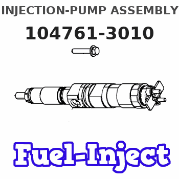
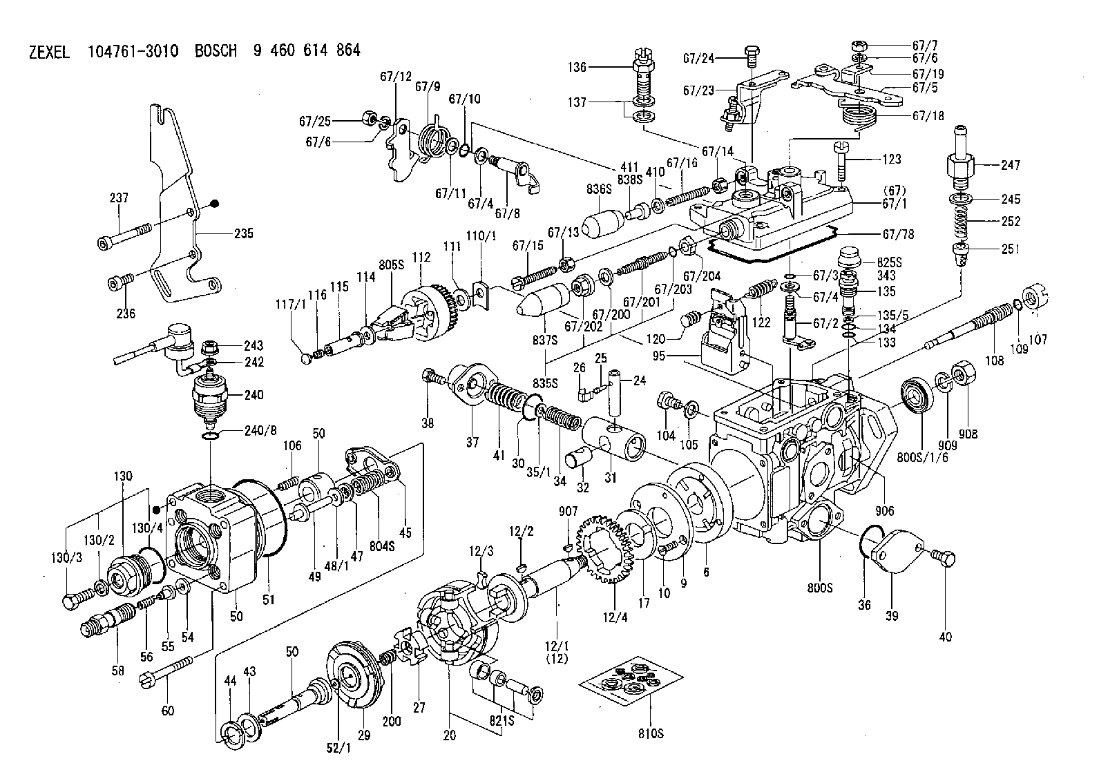
Information injection-pump assembly
BOSCH
9 460 614 864
9460614864
ZEXEL
104761-3010
1047613010
MITSUBISHI-HEAV
32B6500020
32b6500020
Rating:
Compare Prices: .
As an associate, we earn commssions on qualifying purchases through the links below

DJALURTEX S6S Engine High Pressure Common Rail Fuel Injection VE Pump 104661-3010 32B65-00020 Compatible with Mitsubishi Forklift
DJALURTEX S6S Engine High Pressure Common Rail Fuel Injection VE Pump 104661-3010 32B65-00020 Compatible With Mitsubishi Forklift || - Our Good Quality Engine Oil Pump Improves Your Vehicle's Performance And Achieves Better Efficiency. || - Our Engine Oil Pumps Enhance Engine Performance, Improve Fuel Efficiency, And Ensure A Smooth And Powerful Ride. || - Our Engine Oil Pumps Are Made Of Good Quality Materials For Durability. || - We Provide Reliable After-sales Support And Continuously Follow Up On The Status Of Your Order To Give You Peace Of Mind.
DJALURTEX S6S Engine High Pressure Common Rail Fuel Injection VE Pump 104661-3010 32B65-00020 Compatible With Mitsubishi Forklift || - Our Good Quality Engine Oil Pump Improves Your Vehicle's Performance And Achieves Better Efficiency. || - Our Engine Oil Pumps Enhance Engine Performance, Improve Fuel Efficiency, And Ensure A Smooth And Powerful Ride. || - Our Engine Oil Pumps Are Made Of Good Quality Materials For Durability. || - We Provide Reliable After-sales Support And Continuously Follow Up On The Status Of Your Order To Give You Peace Of Mind.

$3,299.99
29 Oct 2024
14.18[6.38] Pounds
Amazon.com
Hacus - Forklift FPE352524 Fuel Pump Assy S6S ZEXEL Hacus Aftermarket - New
Hacus HIGH-QUALITY CONSTRUCTION: Made with premium materials; built to withstand the demands of industrial environments; offering excellent resistance to wear; corrosion; and mechanical stress. || VERSATILE COMPATIBILITY: Engineered to fit a wide range of forklift models; making it a versatile choice for various equipment configurations. || SAFETY FIRST - FPE products are ready for use with all certifications. || LEADING THE INDUSTRY - FPE is a leader in forklift products and accessories. We take pride in making the highest quality, premium, reliable forklifts on the market. || All products tested for durability, reliability, and performance.
Hacus HIGH-QUALITY CONSTRUCTION: Made with premium materials; built to withstand the demands of industrial environments; offering excellent resistance to wear; corrosion; and mechanical stress. || VERSATILE COMPATIBILITY: Engineered to fit a wide range of forklift models; making it a versatile choice for various equipment configurations. || SAFETY FIRST - FPE products are ready for use with all certifications. || LEADING THE INDUSTRY - FPE is a leader in forklift products and accessories. We take pride in making the highest quality, premium, reliable forklifts on the market. || All products tested for durability, reliability, and performance.
You can express buy:
USD 411.32
13-05-2025
13-05-2025
S6S Engine High Pressure Common Rail Fuel Injection VE Pump 104661-3010 32B65-00020 For Mitsubishi Forklift
USD 406.7
13-05-2025
13-05-2025
S6S Engine High Pressure Common Rail Fuel Injection VE Pump 104661-3010 32B65-00020 For Mitsubishi Forklift
USD 436.84
19-05-2025
19-05-2025
S6S Engine High Pressure Common Rail Fuel Injection VE Pump 104661-3010 32B65-00020 For Mitsubishi Forklift
Images:
USD 391.97

[12-May-2025]
USD 1680

[01-May-2025]
USD 1712.87

[19-May-2025]
USD 1712.87

[19-May-2025]
Components :
| 0. | INJECTION-PUMP ASSEMBLY | 104761-3010 |
| 1. | _ | |
| 2. | FUEL INJECTION PUMP | 104661-3010 |
| 3. | NUMBER PLATE | 146989-9300 |
| 4. | _ | |
| 5. | CAPSULE | |
| 6. | ADJUSTING DEVICE | |
| 7. | NOZZLE AND HOLDER ASSY | |
| 8. | Nozzle and Holder | |
| 9. | Open Pre:MPa(Kqf/cm2) | |
| 10. | NOZZLE-HOLDER | |
| 11. | NOZZLE |
Scheme ###:
| 1/6. | [1] | 146601-0900 | PACKING RING |
| 6. | [1] | 146100-0420 | SUPPLY PUMP |
| 9. | [1] | 146103-0100 | COVER |
| 10. | [2] | 139104-0000 | FLAT-HEAD SCREW |
| 12. | [1] | 146200-0020 | DRIVE SHAFT |
| 12/1. | [1] | 146200-0000 | DRIVE SHAFT |
| 12/2. | [1] | 146201-0000 | WOODRUFF KEY |
| 12/3. | [2] | 146202-0100 | DAMPER |
| 12/4. | [1] | 146203-0000 | TOOTHED GEAR |
| 17. | [1] | 146204-0000 | PLAIN WASHER |
| 20. | [1] | 146210-2720 | ROLLER SET |
| 24. | [1] | 146303-0000 | BEARING PIN |
| 25. | [1] | 146304-0000 | BEARING PIN |
| 26. | [1] | 146305-0000 | CLAMPING BAND |
| 27. | [1] | 146205-0000 | SLOTTED WASHER |
| 29. | [1] | 146221-0120 | CAM PLATE |
| 30. | [1] | 146600-0800 | O-RING |
| 31. | [1] | 146311-8820 | PUMP PLUNGER |
| 32. | [1] | 146301-0000 | SLIDING PIECE |
| 34. | [1] | 146312-5200 | COMPRESSION SPRING |
| 34B. | [1] | 146312-6800 | COMPRESSION SPRING |
| 34C. | [1] | 146312-6000 | COMPRESSION SPRING |
| 35/1. | [1] | 146690-3200 | SHIM D11.5&9.4T0.1 |
| 35/1. | [1] | 146690-3300 | SHIM D11.5&9.4T0.2 |
| 35/1. | [1] | 146690-3400 | SHIM D11.5&9.4T0.25 |
| 35/1. | [1] | 146690-3500 | SHIM D11.5&9.4T1.0 |
| 35/1. | [1] | 146690-4100 | SHIM D11.5&9.4T2 |
| 35/1. | [1] | 146690-4200 | SHIM D11.5&9.4T0.5 |
| 35/1. | [1] | 146690-4300 | SHIM D11.5&9.4T0.75 |
| 36. | [1] | 146600-0800 | O-RING |
| 37. | [1] | 146310-4020 | COVER |
| 38. | [2] | 146620-5000 | BLEEDER SCREW |
| 39. | [1] | 146310-0100 | COVER |
| 40. | [2] | 146620-5000 | BLEEDER SCREW |
| 41. | [1] | 146312-1900 | COMPRESSION SPRING |
| 43. | [1] | 146230-0000 | SHIM |
| 44. | [1] | 146230-0100 | PLAIN WASHER |
| 45. | [1] | 146231-0001 | SLOTTED WASHER |
| 47. | [2] | 146233-0000 | SLOTTED WASHER |
| 48/1. | [1] | 146603-0000 | SHIM D17.0&5.2T0.50 |
| 48/1. | [1] | 146603-0100 | SHIM D17.0&5.2T0.80 |
| 48/1. | [1] | 146603-0200 | SHIM D17.0&5.2T1.00 |
| 48/1. | [1] | 146603-0300 | SHIM D17.0&5.2T1.20 |
| 48/1. | [1] | 146603-0400 | SHIM D17.0&5.2T1.50 |
| 48/1. | [1] | 146603-0500 | SHIM D17.0&5.2T1.80 |
| 48/1. | [1] | 146603-0600 | SHIM D17.0&5.2T2.00 |
| 48/1. | [1] | 146690-1400 | SHIM D17&5.2T0.9 |
| 48/1. | [1] | 146690-1500 | SHIM D17&5.2T1.1 |
| 48/1. | [1] | 146690-1600 | SHIM D17&5.2T1.3 |
| 48/1. | [1] | 146690-1700 | SHIM D17&5.2T1.4 |
| 48/1. | [1] | 146690-1800 | SHIM D17&5.2T1.6 |
| 48/1. | [1] | 146690-1900 | SHIM D17&5.2T1.7 |
| 48/1. | [1] | 146690-5800 | SHIM D17&5.2T2.1 |
| 48/1. | [1] | 146690-5900 | SHIM D17&5.2T2.2 |
| 48/1. | [1] | 146690-6000 | SHIM D17&5.2T2.3 |
| 48/1. | [1] | 146690-6100 | SHIM D17&5.2T2.4 |
| 48/1. | [1] | 146690-6200 | SHIM D17&5.2T2.5 |
| 48/1. | [1] | 146690-6300 | SHIM D17&5.2T2.6 |
| 48/1. | [1] | 146690-6400 | SHIM D17&5.2T2.7 |
| 48/1. | [1] | 146690-6500 | SHIM D17&5.2T2.8 |
| 48/1. | [1] | 146690-6600 | SHIM D17&5.2T2.9 |
| 48/1. | [1] | 146690-6700 | SHIM D17&5.2T3.0 |
| 48/1. | [1] | 146690-6800 | SHIM D17&5.2T3.1 |
| 48/1. | [1] | 146690-6900 | SHIM D17&5.2T3.2 |
| 48/1. | [1] | 146690-7000 | SHIM D17&5.2T3.3 |
| 48/1. | [1] | 146690-7100 | SHIM D17&5.2T3.4 |
| 48/1. | [1] | 146690-7200 | SHIM D17&5.2T0.4 |
| 48/1. | [1] | 146690-7300 | SHIM D17&5.2T0.6 |
| 48/1. | [1] | 146690-7400 | SHIM D17&5.2T0.7 |
| 48/1. | [1] | 146690-7500 | SHIM D17&5.2T1.9 |
| 48/1. | [1] | 146690-7800 | SHIM D17&5.2T0.2 |
| 49. | [2] | 146234-0600 | GUIDE PIN |
| 50. | [1] | 146405-4420 | HYDRAULIC HEAD |
| 50. | [1] | 146405-4420 | HYDRAULIC HEAD |
| 50. | [1] | 146405-4420 | HYDRAULIC HEAD |
| 51. | [1] | 146600-0000 | O-RING |
| 52/1. | [1] | 146420-0000 | SHIM D9.5&3.0T1.90 |
| 52/1. | [1] | 146420-0100 | SHIM D9.5&3.0T1.92 |
| 52/1. | [1] | 146420-0200 | SHIM D9.5&3.0T1.94 |
| 52/1. | [1] | 146420-0300 | SHIM D9.5&3.0T1.96 |
| 52/1. | [1] | 146420-0400 | SHIM D9.5&3.0T1.98 |
| 52/1. | [1] | 146420-0500 | SHIM D9.5&3.0T2.00 |
| 52/1. | [1] | 146420-0600 | SHIM D9.5&3.0T2.02 |
| 52/1. | [1] | 146420-0700 | SHIM D9.5&3.0T2.04 |
| 52/1. | [1] | 146420-0800 | SHIM D9.5&3.0T2.06 |
| 52/1. | [1] | 146420-0900 | SHIM D9.5&3.0T2.08 |
| 52/1. | [1] | 146420-1000 | SHIM D9.5&3.0T2.10 |
| 52/1. | [1] | 146420-1100 | SHIM D9.5&3.0T2.12 |
| 52/1. | [1] | 146420-1200 | SHIM D9.5&3.0T2.14 |
| 52/1. | [1] | 146420-1300 | SHIM D9.5&3.0T2.16 |
| 52/1. | [1] | 146420-1400 | SHIM D9.5&3.0T2.18 |
| 52/1. | [1] | 146420-1500 | SHIM D9.5&3.0T2.20 |
| 52/1. | [1] | 146420-1600 | SHIM D9.5&3.0T2.22 |
| 52/1. | [1] | 146420-1700 | SHIM D9.5&3.0T2.24 |
| 52/1. | [1] | 146420-1800 | SHIM D9.5&3.0T2.26 |
| 52/1. | [1] | 146420-1900 | SHIM D9.5&3.0T2.28 |
| 52/1. | [1] | 146420-2000 | SHIM D9.5&3.0T2.30 |
| 52/1. | [1] | 146420-2100 | SHIM D9.5&3.0T2.32 |
| 52/1. | [1] | 146420-2200 | SHIM D9.5&3.0T2.34 |
| 52/1. | [1] | 146420-2300 | SHIM D9.5&3.0T2.36 |
| 52/1. | [1] | 146420-2400 | SHIM D9.5&3.0T2.38 |
| 52/1. | [1] | 146420-2500 | SHIM D9.5&3.0T2.40 |
| 52/1. | [1] | 146420-2600 | SHIM D9.5&3.0T2.42 |
| 52/1. | [1] | 146420-2700 | SHIM D9.5&3.0T2.44 |
| 52/1. | [1] | 146420-2800 | SHIM D9.5&3.0T2.46 |
| 52/1. | [1] | 146420-2900 | SHIM D9.5&3.0T2.48 |
| 52/1. | [1] | 146420-3000 | SHIM D9.5&3.0T2.50 |
| 52/1. | [1] | 146420-3100 | SHIM D9.5&3.0T2.52 |
| 52/1. | [1] | 146420-3200 | SHIM D9.5&3.0T2.54 |
| 52/1. | [1] | 146420-3300 | SHIM D9.5&3.0T2.56 |
| 52/1. | [1] | 146420-3400 | SHIM D9.5&3.0T2.58 |
| 52/1. | [1] | 146420-3500 | SHIM D9.5&3.0T2.60 |
| 52/1. | [1] | 146420-3600 | SHIM D9.5&3.0T2.62 |
| 52/1. | [1] | 146420-3700 | SHIM D9.5&3.0T2.64 |
| 52/1. | [1] | 146420-3800 | SHIM D9.5&3.0T2.66 |
| 52/1. | [1] | 146420-3900 | SHIM D9.5&3.0T2.68 |
| 52/1. | [1] | 146420-4000 | SHIM D9.5&3.0T2.70 |
| 52/1. | [1] | 146420-4100 | SHIM D9.5&3.0T2.72 |
| 52/1. | [1] | 146420-4200 | SHIM D9.5&3.0T2.74 |
| 52/1. | [1] | 146420-4300 | SHIM D9.5&3.0T2.76 |
| 52/1. | [1] | 146420-4400 | SHIM D9.5&3.0T2.78 |
| 52/1. | [1] | 146420-4500 | SHIM D9.5&3.0T2.80 |
| 52/1. | [1] | 146420-4600 | SHIM D9.5&3.0T2.82 |
| 52/1. | [1] | 146420-4700 | SHIM D9.5&3.0T2.84 |
| 52/1. | [1] | 146420-4800 | SHIM D9.5&3.0T2.86 |
| 52/1. | [1] | 146420-4900 | SHIM D9.5&3.0T2.88 |
| 52/1. | [1] | 146420-5000 | SHIM D9.5&3.0T2.90 |
| 52/1. | [1] | 146420-5100 | SHIM D9.5&3.0T1.74 |
| 52/1. | [1] | 146420-5200 | SHIM D9.5&3.0T1.76 |
| 52/1. | [1] | 146420-5300 | SHIM D9.5&3.0T1.78 |
| 52/1. | [1] | 146420-5400 | SHIM D9.5&3.0T1.80 |
| 52/1. | [1] | 146420-5500 | SHIM D9.5&3.0T1.82 |
| 52/1. | [1] | 146420-5600 | SHIM D9.5&3.0T1.84 |
| 52/1. | [1] | 146420-5700 | SHIM D9.5&3.0T1.86 |
| 52/1. | [1] | 146420-5800 | SHIM D9.5&3.0T1.88 |
| 54. | [6] | 146433-0100 | GASKET |
| 55. | [6] | 146430-3320 | DELIVERY-VALVE ASSEMBLY VE33 |
| 56. | [6] | 146432-0000 | COMPRESSION SPRING |
| 58. | [6] | 146440-0220 | FITTING |
| 60. | [3] | 139106-0100 | FLAT-HEAD SCREW |
| 67. | [1] | 146822-1220 | GOVERNOR COVER |
| 67/1. | [1] | 146508-1022 | GOVERNOR COVER |
| 67/2. | [1] | 146515-0320 | CONTROL SHAFT |
| 67/3. | [1] | 146600-0100 | O-RING |
| 67/4. | [2] | 139310-0200 | PLAIN WASHER |
| 67/4. | [2] | 139310-0200 | PLAIN WASHER |
| 67/5. | [1] | 146832-5500 | CONTROL LEVER MARK:255 |
| 67/5B. | [1] | 146832-5600 | CONTROL LEVER MARK:256 |
| 67/5C. | [1] | 146832-9300 | CONTROL LEVER MARK:293 |
| 67/5D. | [1] | 146832-9400 | CONTROL LEVER MARK:294 |
| 67/6. | [2] | 014110-6440 | LOCKING WASHER D12.2&6.1T1.5 |
| 67/6. | [2] | 014110-6440 | LOCKING WASHER D12.2&6.1T1.5 |
| 67/7. | [1] | 013020-6040 | UNION NUT |
| 67/8. | [1] | 146515-1820 | LEVER SHAFT |
| 67/9. | [1] | 146587-4500 | COILED SPRING |
| 67/10. | [1] | 146600-0200 | O-RING |
| 67/11. | [1] | 146602-0100 | PLAIN WASHER |
| 67/12. | [1] | 146540-1300 | CONTROL LEVER |
| 67/12B. | [1] | 146540-1400 | CONTROL LEVER MARK:0 |
| 67/12C. | [1] | 146540-5200 | CONTROL LEVER |
| 67/12D. | [1] | 146540-5300 | CONTROL LEVER |
| 67/13. | [1] | 146621-1700 | UNION NUT |
| 67/14. | [1] | 146621-1700 | UNION NUT |
| 67/15. | [1] | 146526-3400 | BLEEDER SCREW |
| 67/16. | [1] | 146526-7300 | FLAT-HEAD SCREW |
| 67/18. | [1] | 146587-0400 | COILED SPRING |
| 67/19. | [1] | 146541-0000 | ANGLE PIECE |
| 67/23. | [1] | 146925-2520 | BRACKET |
| 67/24. | [2] | 139006-4500 | BLEEDER SCREW |
| 67/25. | [1] | 013020-6040 | UNION NUT |
| 67/78. | [1] | 146600-4400 | SEAL RING |
| 67/200. | [1] | 139308-0300 | PLAIN WASHER |
| 67/201. | [1] | 146545-4600 | THREADED PIN L=24MM |
| 67/201B. | [1] | 146545-4700 | THREADED PIN L=26MM |
| 67/201C. | [1] | 146545-4800 | THREADED PIN L=28MM |
| 67/202. | [1] | 146598-5000 | UNION NUT |
| 67/203. | [1] | 146600-1200 | O-RING |
| 67/204. | [1] | 146545-4500 | DAMPER |
| 95. | [1] | 146871-8020 | FULCRUM LEVER |
| 104. | [2] | 146568-0000 | SLOTTED SPRING PIN |
| 105. | [2] | 026508-1140 | GASKET D11.4&8.2T1.0 |
| 106. | [2] | 146588-0500 | COILED SPRING |
| 107. | [1] | 146569-0300 | UNION NUT |
| 108. | [1] | 146570-0420 | GOVERNOR SHAFT |
| 109. | [1] | 146600-0400 | O-RING |
| 110/1. | [1] | 146571-0000 | SHIM D20.2&8.3T1.05 |
| 110/1. | [1] | 146571-0100 | SHIM D20.2&8.3T1.25 |
| 110/1. | [1] | 146571-0200 | SHIM D20.2&8.3T1.45 |
| 110/1. | [1] | 146571-0300 | SHIM D20.2&8.3T1.65 |
| 110/1. | [1] | 146571-0400 | SHIM D20.2&8.3T1.85 |
| 110/1. | [1] | 146571-0500 | SHIM D20.2&8.3T1.15 |
| 110/1. | [1] | 146571-0600 | SHIM D20.2&8.3T1.35 |
| 110/1. | [1] | 146571-0700 | SHIM D20.2&8.3T1.55 |
| 110/1. | [1] | 146571-0800 | SHIM D20.2&8.3T1.75 |
| 111. | [1] | 146602-0600 | PLAIN WASHER |
| 112. | [1] | 146572-0020 | FLYWEIGHT ASSEMBLY |
| 114. | [1] | 146602-2600 | PLAIN WASHER |
| 115. | [1] | 146976-1200 | SLIDING SLEEVE |
| 116. | [1] | 146576-0200 | CAP |
| 117/1. | [1] | 146577-1800 | PLUG L2.10 |
| 117/1. | [1] | 146577-1900 | PLUG L2.30 |
| 117/1. | [1] | 146577-2000 | PLUG L2.50 |
| 117/1. | [1] | 146577-2100 | PLUG L2.70 |
| 117/1. | [1] | 146577-2200 | PLUG L2.90 |
| 117/1. | [1] | 146577-2300 | PLUG L3.10 |
| 117/1. | [1] | 146577-2400 | PLUG L3.30 |
| 117/1. | [1] | 146577-2500 | PLUG L3.50 |
| 117/1. | [1] | 146577-2600 | PLUG L3.70 |
| 117/1. | [1] | 146577-2700 | PLUG L3.90 |
| 117/1. | [1] | 146577-2800 | PLUG L4.10 |
| 117/1. | [1] | 146577-2900 | PLUG L4.30 |
| 117/1. | [1] | 146577-3000 | PLUG L4.50 |
| 117/1. | [1] | 146577-3100 | PLUG L4.70 |
| 117/1. | [1] | 146577-3200 | PLUG L4.90 |
| 117/1. | [1] | 146577-3300 | PLUG L5.10 |
| 117/1. | [1] | 146577-6700 | PLUG L2.2 |
| 117/1. | [1] | 146577-6800 | PLUG L2.4 |
| 117/1. | [1] | 146577-6900 | PLUG L2.6 |
| 117/1. | [1] | 146577-7000 | PLUG L2.8 |
| 117/1. | [1] | 146577-7100 | PLUG L3.0 |
| 117/1. | [1] | 146577-7200 | PLUG L3.2 |
| 117/1. | [1] | 146577-7300 | PLUG L3.4 |
| 117/1. | [1] | 146577-7400 | PLUG L3.6 |
| 117/1. | [1] | 146577-7500 | PLUG L3.8 |
| 117/1. | [1] | 146577-7600 | PLUG L4.0 |
| 117/1. | [1] | 146577-7700 | PLUG L4.2 |
| 117/1. | [1] | 146577-7800 | PLUG L4.4 |
| 117/1. | [1] | 146577-7900 | PLUG L4.6 |
| 117/1. | [1] | 146577-8000 | PLUG L4.8 |
| 117/1. | [1] | 146577-8100 | PLUG L5.0 |
| 117/1. | [1] | 146877-0000 | PLUG L5.2 |
| 117/1. | [1] | 146877-0100 | PLUG L5.3 |
| 117/1. | [1] | 146877-0200 | PLUG L5.4 |
| 117/1. | [1] | 146877-0300 | PLUG L5.5 |
| 117/1. | [1] | 146877-4700 | PLUG L5.6 |
| 117/1. | [1] | 146877-4800 | PLUG L5.7 |
| 117/1. | [1] | 146877-4900 | PLUG L5.8 |
| 117/1. | [1] | 146877-5000 | PLUG L5.9 |
| 120. | [1] | 146879-3720 | RETAINING PIN |
| 122. | [1] | 146580-1400 | GOVERNOR SPRING |
| 123. | [4] | 139106-0200 | FLAT-HEAD SCREW |
| 130. | [1] | 146421-0020 | CAPSULE |
| 130/2. | [1] | 026508-1140 | GASKET D11.4&8.2T1.0 |
| 130/3. | [1] | 146422-0000 | BLEEDER SCREW |
| 130/4. | [1] | 146600-0500 | O-RING |
| 133. | [1] | 146600-0600 | O-RING |
| 134. | [1] | 146600-0700 | O-RING |
| 135. | [1] | 146110-3720 | CONTROL VALVE |
| 135/5. | [1] | 146114-0000 | SPRING WASHER |
| 136. | [1] | 146120-0120 | OVER FLOW VALVE |
| 137. | [2] | 139512-0500 | GASKET |
| 200. | [1] | 146206-0100 | COILED SPRING |
| 235. | [1] | 146936-3000 | BRACKET |
| 236. | [2] | 010206-2240 | HEX-SOCKET-HEAD CAP SCREW |
| 237. | [1] | 146620-0200 | HEX-SOCKET-HEAD CAP SCREW |
| 240. | [1] | 146650-0820 | PULLING ELECTROMAGNET |
| 240/8. | [1] | 146600-1700 | O-RING |
| 242. | [1] | 146662-0120 | WIRE |
| 243. | [1] | 146621-4901 | UNION NUT |
| 245. | [1] | 139512-0500 | GASKET |
| 247. | [1] | 146669-1720 | INLET UNION |
| 251. | [1] | 146125-0101 | FILTER |
| 252. | [1] | 146125-0200 | COILED SPRING |
| 343. | [1] | 146598-8700 | CAP NUT |
| 410. | [1] | 014020-6140 | PLAIN WASHER D11.5&6.5 |
| 411. | [1] | 146598-6300 | CAP NUT |
| 800S. | [1] | 146020-1820 | PUMP HOUSING |
| 800S/1/6. | [1] | 146601-0900 | PACKING RING |
| 804S. | [1] | 146232-0720 | COMPRESSION SPRING |
| 805S. | [1] | 146574-0320 | PARTS SET |
| 810S. | [1] | 146600-1120 | REPAIR SET |
| 821S. | [1] | 146210-5720 | ROLLER SET |
| 825S. | [1] | 146598-8600 | CAP NUT |
| 835S. | [1] | 146598-7320 | CAP |
| 836S. | [1] | 146598-7920 | CAP |
| 837S. | [1] | 146598-7310 | CAP |
| 838S. | [1] | 146598-6710 | CAP |
| 906. | [1] | 146989-9300 | NAMEPLATE |
| 907. | [1] | 025803-1640 | WOODRUFF KEY |
| 908. | [1] | 013021-2140 | UNION NUT |
| 909. | [1] | 014111-2440 | LOCKING WASHER |
Include in #2:
104761-3010
as INJECTION-PUMP ASSEMBLY
Cross reference number
BOSCH
9 460 614 864
9460614864
ZEXEL
104761-3010
1047613010
MITSUBISHI-HEAV
32B6500020
32b6500020
Zexel num
Bosch num
Firm num
Name
9 460 614 864
32B6500020 MITSUBISHI-HEAV
INJECTION-PUMP ASSEMBLY
S6S * K 11CK INJECTION PUMP ASSY VE6 VE
S6S * K 11CK INJECTION PUMP ASSY VE6 VE
Calibration Data:
Adjustment conditions
Test oil
1404 Test oil ISO4113orSAEJ967d
1404 Test oil ISO4113orSAEJ967d
Test oil temperature
degC
45
45
50
Nozzle
105780-0060
Bosch type code
NP-DN0SD1510
Nozzle holder
105780-2150
Opening pressure
MPa
13
13
13.3
Opening pressure
kgf/cm2
133
133
136
Injection pipe
157805-7320
Injection pipe
Inside diameter - outside diameter - length (mm) mm 2-6-450
Inside diameter - outside diameter - length (mm) mm 2-6-450
Joint assembly
157641-4720
Tube assembly
157641-4020
Transfer pump pressure
kPa
20
20
20
Transfer pump pressure
kgf/cm2
0.2
0.2
0.2
Direction of rotation (viewed from drive side)
Right R
Right R
Injection timing adjustment
Pump speed
r/min
800
800
800
Average injection quantity
mm3/st.
48.2
47.7
48.7
Difference in delivery
mm3/st.
4.5
Basic
*
Oil temperature
degC
50
48
52
Injection timing adjustment_02
Pump speed
r/min
300
300
300
Average injection quantity
mm3/st.
48.9
43.4
54.4
Oil temperature
degC
48
46
50
Injection timing adjustment_03
Pump speed
r/min
800
800
800
Average injection quantity
mm3/st.
48.2
47.2
49.2
Difference in delivery
mm3/st.
5
Basic
*
Oil temperature
degC
50
48
52
Injection timing adjustment_04
Pump speed
r/min
900
900
900
Average injection quantity
mm3/st.
48.9
44.9
52.9
Oil temperature
degC
50
48
52
Injection timing adjustment_05
Pump speed
r/min
1150
1150
1150
Average injection quantity
mm3/st.
45.1
40.6
49.6
Oil temperature
degC
50
48
52
Injection quantity adjustment
Pump speed
r/min
1285
1285
1285
Average injection quantity
mm3/st.
8.6
6.6
10.6
Difference in delivery
mm3/st.
2
Basic
*
Oil temperature
degC
50
48
52
Injection quantity adjustment_02
Pump speed
r/min
1400
1400
1400
Average injection quantity
mm3/st.
3
Oil temperature
degC
50
48
52
Injection quantity adjustment_03
Pump speed
r/min
1285
1285
1285
Average injection quantity
mm3/st.
8.6
6.1
11.1
Difference in delivery
mm3/st.
2.5
Basic
*
Oil temperature
degC
50
48
52
Governor adjustment
Pump speed
r/min
410
410
410
Average injection quantity
mm3/st.
9.7
7.7
11.7
Difference in delivery
mm3/st.
2
Basic
*
Oil temperature
degC
48
46
50
Governor adjustment_02
Pump speed
r/min
410
410
410
Average injection quantity
mm3/st.
9.7
7.2
12.2
Difference in delivery
mm3/st.
2.5
Basic
*
Oil temperature
degC
48
46
50
Timer adjustment
Pump speed
r/min
100
100
100
Average injection quantity
mm3/st.
50
45
55
Basic
*
Oil temperature
degC
48
46
50
Remarks
Full
Full
Timer adjustment_02
Pump speed
r/min
100
100
100
Average injection quantity
mm3/st.
50
45
55
Oil temperature
degC
48
46
50
Remarks
Full
Full
Speed control lever angle
Pump speed
r/min
410
410
410
Average injection quantity
mm3/st.
0
0
0
Oil temperature
degC
48
46
50
Remarks
Magnet OFF at idling position
Magnet OFF at idling position
0000000901
Pump speed
r/min
800
800
800
Overflow quantity
cm3/min
420
290
550
Oil temperature
degC
50
48
52
Stop lever angle
Pump speed
r/min
800
800
800
Pressure
kPa
549
529
569
Pressure
kgf/cm2
5.6
5.4
5.8
Basic
*
Oil temperature
degC
50
48
52
0000001101
Pump speed
r/min
800
800
800
Timer stroke
mm
1.3
0.9
1.7
Basic
*
Oil temperature
degC
50
48
52
_02
Pump speed
r/min
700
700
700
Timer stroke
mm
0.9
0.3
1.5
Oil temperature
degC
50
48
52
_03
Pump speed
r/min
800
800
800
Timer stroke
mm
1.3
0.9
1.7
Basic
*
Oil temperature
degC
50
48
52
_04
Pump speed
r/min
900
900
900
Timer stroke
mm
1.7
1.1
2.3
Oil temperature
degC
50
48
52
_05
Pump speed
r/min
1150
1150
1150
Timer stroke
mm
2.1
1.6
2.5
Oil temperature
degC
50
48
52
0000001201
Max. applied voltage
V
16
16
16
Test voltage
V
25
24
26
0000001401
Pump speed
r/min
900
900
900
Average injection quantity
mm3/st.
12.3
11.3
13.3
Timer stroke TA
mm
0.8
0.3
1.3
Basic
*
Oil temperature
degC
50
48
52
_02
Pump speed
r/min
1100
1100
1100
Average injection quantity
mm3/st.
22
20
24
Timer stroke TA
mm
2.1
1.6
2.5
Timer stroke variation dT
mm
0
0
0
Oil temperature
degC
50
48
52
_03
Pump speed
r/min
1100
1100
1100
Average injection quantity
mm3/st.
11.7
9.7
13.7
Timer stroke TA
mm
0.8
0
1.8
Timer stroke variation dT
mm
1.3
1.3
1.3
Oil temperature
degC
50
48
52
Timing setting
K dimension
mm
3.3
3.2
3.4
KF dimension
mm
6.94
6.84
7.04
MS dimension
mm
2.5
2.4
2.6
Pre-stroke
mm
0.1
0.08
0.12
Control lever angle alpha
deg.
25
21
29
Control lever angle beta
deg.
30
25
35
Test data Ex:
0000001801 STARTING I/Q ADJUSTMENT

Starting Q decrease lever adjustment
Adjust using the screw (A) so that the standards are satisfied, then fix using the nut (B) (Torque to T after adjustment)
Screw protrusion: L
(C) = Cap
(D) = Stop lever
----------
L=7.4~11.1mm T=6~9N-m(0.6~0.9kgf-m)
----------
L=7.4~11.1mm T=6~9N-m(0.6~0.9kgf-m) SW=SW10
----------
L=7.4~11.1mm T=6~9N-m(0.6~0.9kgf-m)
----------
L=7.4~11.1mm T=6~9N-m(0.6~0.9kgf-m) SW=SW10
Information:
The cylinder head is either water-cooled or air-cooled by fins in order to prevent overheating by the compression heat of the air compressor.The water-cooled type has coolant led from the oil cooler to cool cylinder head valves. Coolant is then returned to the rear end of the engine cylinder head.1.2 Pressure Governor
The pressure governor controls compressor operation to keep the air tank pressure within specified limits.To the high pressure valve of the diaphragm, the same air pressure as in the air tank acts always through the filter, thereby balancing with the adjusting spring force. When the pressure in the air tank increases to exceed that opening pressure of the high pressure valve, the air forces up the high pressure valve seat of the diaphragm. This causes increase of acting area so that the diaphragm moves up quickly to close the seat of the low pressure valve.When the low pressure valve is closed, air now flows through the valve body to force down the unloader valve of the air compressor, thereby stopping air supply to the air tank.As the air pressure in the air tank gradually drops, the diaphragm is forced down by the adjusting spring and the low pressure valve opens and the high pressure one closes. As a result, the air on the unloader side is exhausted through the exhaust hole and air supply to the air tank is resumed.2. Specifications
3. Service Standards
3.1 Service Standards Table
(1) Air Compressor (2) Pressure Governor 3.2 Tightening Torque Table
(1) Air compressor (2) Pressure governor 4. Special Tool
5. Service Procedure
5.1 Air Compressor
Removal and installation
The removal and installation procedures of the air compressor are same as those of the pump drive case. See Group 13 Fuel and Engine Control.Disassembly
Disassembly(1) Removal of suction valve holder Using special tool, Air Compressor Suction Valve Tool, remove the suction valve holder.(2) Removal of delivery valve holder (Air-cooled type only) Using special tool, Air Compressor Delivery Valve Tool, remove the delivery valve holder.(3) Removal of piston ring Using special tool, Piston Ring Tool, remove the piston ring.Inspection
Inspection(1) Piston to cylinder liner clearance Calculate the clearance and if it exceeds the limit, replace the piston or cylinder liner.(2) Piston ring to ring groove clearance Measure the clearance and if it exceeds the limit, replace the piston ring or piston. Measure over entire circumference of the piston.(3) Piston ring open end gap Fit the piston ring to a new cylinder liner or gauge and measure the open end gap. If the gap exceeds the limit, replace the ring. Push in the piston ring flat by the piston and measure.(4) Piston to piston pin clearance Calculate the clearance and if it exceeds the limit, replace the piston or piston pin.(5) Piston to connecting rod clearance Calculate the clearance and if it exceeds the limit, replace the piston pin or connecting rod.(6) Crankshaft pin to connecting rod bearing clearance Calculate the clearance and if it exceeds the limit, replace the bearing.(7) Connecting rod end play If the end play exceeds the limit,