Information injection-pump assembly
ZEXEL
104761-2011
1047612011
NISSAN
167000Y010
167000y010
Rating:
Cross reference number
ZEXEL
104761-2011
1047612011
NISSAN
167000Y010
167000y010
Zexel num
Bosch num
Firm num
Name
Calibration Data:
Adjustment conditions
Test oil
1404 Test oil ISO4113orSAEJ967d
1404 Test oil ISO4113orSAEJ967d
Test oil temperature
degC
45
45
50
Nozzle
105780-0060
Bosch type code
NP-DN0SD1510
Nozzle holder
105780-2150
Opening pressure
MPa
13
13
13.3
Opening pressure
kgf/cm2
133
133
136
Injection pipe
157805-7320
Injection pipe
Inside diameter - outside diameter - length (mm) mm 2-6-450
Inside diameter - outside diameter - length (mm) mm 2-6-450
Joint assembly
157641-4720
Tube assembly
157641-4020
Transfer pump pressure
kPa
20
20
20
Transfer pump pressure
kgf/cm2
0.2
0.2
0.2
Direction of rotation (viewed from drive side)
Right R
Right R
(Solenoid timer adjustment condition)
OFF
Injection timing adjustment
Pump speed
r/min
600
600
600
Boost pressure
kPa
0
0
0
Boost pressure
mmHg
0
0
0
Average injection quantity
mm3/st.
31.1
30.6
31.6
Difference in delivery
mm3/st.
2
Basic
*
Oil temperature
degC
50
48
52
Remarks
NA
NA
Injection timing adjustment_02
Pump speed
r/min
600
600
600
Boost pressure
kPa
16
14.7
17.3
Boost pressure
mmHg
120
110
130
Average injection quantity
mm3/st.
34.2
33.7
34.7
Difference in delivery
mm3/st.
2
Basic
*
Oil temperature
degC
50
48
52
Remarks
CBS
CBS
Injection timing adjustment_03
Pump speed
r/min
500
500
500
Boost pressure
kPa
0
0
0
Boost pressure
mmHg
0
0
0
Average injection quantity
mm3/st.
31.1
29.1
33.1
Oil temperature
degC
48
46
50
Injection timing adjustment_04
Pump speed
r/min
600
600
600
Boost pressure
kPa
0
0
0
Boost pressure
mmHg
0
0
0
Average injection quantity
mm3/st.
31.1
30.1
32.1
Difference in delivery
mm3/st.
2.5
Basic
*
Oil temperature
degC
50
48
52
Injection timing adjustment_05
Pump speed
r/min
600
600
600
Boost pressure
kPa
8.7
6.7
10.7
Boost pressure
mmHg
65
50
80
Average injection quantity
mm3/st.
31.1
30.1
32.1
Oil temperature
degC
50
48
52
Injection timing adjustment_06
Pump speed
r/min
600
600
600
Boost pressure
kPa
16
14.7
17.3
Boost pressure
mmHg
120
110
130
Average injection quantity
mm3/st.
34.2
33.2
35.2
Difference in delivery
mm3/st.
2.5
Basic
*
Oil temperature
degC
50
48
52
Injection timing adjustment_07
Pump speed
r/min
1200
1200
1200
Boost pressure
kPa
66.7
65.4
68
Boost pressure
mmHg
500
490
510
Average injection quantity
mm3/st.
45.2
42.7
47.7
Oil temperature
degC
50
48
52
Injection timing adjustment_08
Pump speed
r/min
1800
1800
1800
Boost pressure
kPa
66.7
65.4
68
Boost pressure
mmHg
500
490
510
Average injection quantity
mm3/st.
45
42
48
Oil temperature
degC
50
48
52
Injection timing adjustment_09
Pump speed
r/min
2200
2200
2200
Boost pressure
kPa
66.7
65.4
68
Boost pressure
mmHg
500
490
510
Average injection quantity
mm3/st.
43.6
40.6
46.6
Oil temperature
degC
52
50
54
Injection timing adjustment_10
Pump speed
r/min
2300
2300
2300
Boost pressure
kPa
66.7
65.4
68
Boost pressure
mmHg
500
490
510
Average injection quantity
mm3/st.
43.7
40.2
47.2
Oil temperature
degC
52
50
54
Injection quantity adjustment
Pump speed
r/min
2500
2500
2500
Boost pressure
kPa
66.7
65.4
68
Boost pressure
mmHg
500
490
510
Average injection quantity
mm3/st.
20.5
19.5
21.5
Difference in delivery
mm3/st.
4.5
Basic
*
Oil temperature
degC
55
52
58
Injection quantity adjustment_02
Pump speed
r/min
2500
2500
2500
Boost pressure
kPa
66.7
65.4
68
Boost pressure
mmHg
500
490
510
Average injection quantity
mm3/st.
20.5
19
22
Difference in delivery
mm3/st.
5
Basic
*
Oil temperature
degC
55
52
58
Injection quantity adjustment_03
Pump speed
r/min
2800
2800
2800
Boost pressure
kPa
66.7
65.4
68
Boost pressure
mmHg
500
490
510
Average injection quantity
mm3/st.
4.5
Oil temperature
degC
55
52
58
Governor adjustment
Pump speed
r/min
375
375
375
Boost pressure
kPa
0
0
0
Boost pressure
mmHg
0
0
0
Average injection quantity
mm3/st.
14
13
15
Difference in delivery
mm3/st.
1.7
Basic
*
Oil temperature
degC
48
46
50
Governor adjustment_02
Pump speed
r/min
375
375
375
Boost pressure
kPa
0
0
0
Boost pressure
mmHg
0
0
0
Average injection quantity
mm3/st.
14
12
16
Difference in delivery
mm3/st.
2.4
Basic
*
Oil temperature
degC
48
46
50
Governor adjustment_03
Pump speed
r/min
800
800
800
Boost pressure
kPa
0
0
0
Boost pressure
mmHg
0
0
0
Average injection quantity
mm3/st.
5
Oil temperature
degC
50
48
52
Boost compensator adjustment
Pump speed
r/min
600
600
600
Boost pressure
kPa
0
0
0
Boost pressure
mmHg
0
0
0
Average injection quantity
mm3/st.
29.2
22.7
35.7
Oil temperature
degC
50
48
52
Lever angle (shim thickness)
mm
5.6
5.55
5.65
Remarks
From idle
From idle
Boost compensator adjustment_02
Pump speed
r/min
900
900
900
Boost pressure
kPa
0
0
0
Boost pressure
mmHg
0
0
0
Average injection quantity
mm3/st.
19.5
12.5
26.5
Oil temperature
degC
50
48
52
Lever angle (shim thickness)
mm
5.6
5.55
5.65
Remarks
From idle
From idle
Timer adjustment
Pump speed
r/min
100
100
100
Boost pressure
kPa
0
0
0
Boost pressure
mmHg
0
0
0
Average injection quantity
mm3/st.
40
40
Basic
*
Oil temperature
degC
48
46
50
Timer adjustment_02
Pump speed
r/min
100
100
100
Boost pressure
kPa
0
0
0
Boost pressure
mmHg
0
0
0
Average injection quantity
mm3/st.
40
40
Oil temperature
degC
48
46
50
Speed control lever angle
Pump speed
r/min
375
375
375
Boost pressure
kPa
0
0
0
Boost pressure
mmHg
0
0
0
Average injection quantity
mm3/st.
6
Oil temperature
degC
48
46
50
Remarks
Magnet OFF at idling position
Magnet OFF at idling position
Speed control lever angle_02
Pump speed
r/min
600
600
600
Boost pressure
kPa
0
0
0
Boost pressure
mmHg
0
0
0
Average injection quantity
mm3/st.
0
0
0
Oil temperature
degC
50
48
52
Remarks
Magnet OFF at full-load position
Magnet OFF at full-load position
0000000901
Pump speed
r/min
900
900
900
Boost pressure
kPa
66.7
65.4
68
Boost pressure
mmHg
500
490
510
Overflow quantity with S/T OFF
cm3/min
390
260
520
Oil temperature
degC
50
48
52
Stop lever angle
Pump speed
r/min
900
900
900
Boost pressure
kPa
66.7
65.4
68
Boost pressure
mmHg
500
490
510
Pressure with S/T ON
kPa
353
314
392
Pressure with S/T ON
kgf/cm2
3.6
3.2
4
Pressure with S/T OFF
kPa
431
402
460
Pressure with S/T OFF
kgf/cm2
4.4
4.1
4.7
Basic
*
Oil temperature
degC
50
48
52
Remarks
OFF
OFF
Stop lever angle_02
Pump speed
r/min
900
900
900
Boost pressure
kPa
66.7
65.4
68
Boost pressure
mmHg
500
490
510
Pressure with S/T ON
kPa
353
304
402
Pressure with S/T ON
kgf/cm2
3.6
3.1
4.1
Pressure with S/T OFF
kPa
431
392
470
Pressure with S/T OFF
kgf/cm2
4.4
4
4.8
Basic
*
Oil temperature
degC
50
48
52
Stop lever angle_03
Pump speed
r/min
1200
1200
1200
Boost pressure
kPa
66.7
65.4
68
Boost pressure
mmHg
500
490
510
Pressure with S/T OFF
kPa
490
451
529
Pressure with S/T OFF
kgf/cm2
5
4.6
5.4
Oil temperature
degC
50
48
52
Stop lever angle_04
Pump speed
r/min
2300
2300
2300
Boost pressure
kPa
66.7
65.4
68
Boost pressure
mmHg
500
490
510
Pressure with S/T OFF
kPa
765
726
804
Pressure with S/T OFF
kgf/cm2
7.8
7.4
8.2
Oil temperature
degC
52
50
54
0000001101
Pump speed
r/min
900
900
900
Boost pressure
kPa
66.7
65.4
68
Boost pressure
mmHg
500
490
510
Timer stroke with S/T ON
mm
1.7
1.4
2
Timer stroke with S/T OFF
mm
3.4
3.2
3.6
Basic
*
Oil temperature
degC
50
48
52
Remarks
OFF
OFF
_02
Pump speed
r/min
900
900
900
Boost pressure
kPa
66.7
65.4
68
Boost pressure
mmHg
500
490
510
Timer stroke with S/T ON
mm
1.7
1.3
2.1
Timer stroke with S/T OFF
mm
3.4
3.1
3.7
Basic
*
Oil temperature
degC
50
48
52
_03
Pump speed
r/min
1200
1200
1200
Boost pressure
kPa
66.7
65.4
68
Boost pressure
mmHg
500
490
510
Timer stroke with S/T OFF
mm
5.2
4.8
5.6
Oil temperature
degC
50
48
52
_04
Pump speed
r/min
2300
2300
2300
Boost pressure
kPa
66.7
65.4
68
Boost pressure
mmHg
500
490
510
Timer stroke with S/T OFF
mm
9.8
9.3
10.2
Oil temperature
degC
52
50
54
0000001201
Max. applied voltage
V
8
8
8
Test voltage
V
13
12
14
Timing setting
K dimension
mm
3.3
3.2
3.4
KF dimension
mm
7.22
7.12
7.32
MS dimension
mm
1.8
1.7
1.9
BCS stroke
mm
2.9
2.9
2.9
Control lever angle alpha
deg.
23
19
27
Control lever angle beta
deg.
42
37
47
Test data Ex:
0000001801 POTENTIOMETER ADJUSTMENT
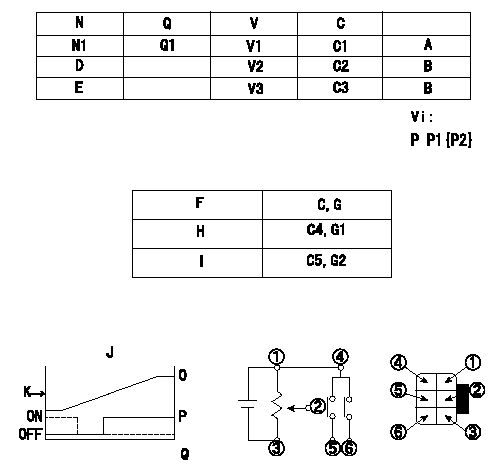
Adjustment of the potentiometer
1. Determine the position of the control lever at the adjusting point. Fix with the dummy bolt contacting the lever.
2. In the fixed position, install the potentiometer so that the output voltage is V1 (supply voltage Vi).
3. After completing potentiometer installation, remove the dummy bolt.
N:Pump speed
Q:Injection quantity
V:Output voltage
P:Boost pressure
A:Adjusting point
B:Checking point
C:Control lever angle
D:Idle lever angle
E:Full speed lever angle
F:Conversion point
G:From idle
H:ON-->OFF
I:OFF-->ON
J:Connecting diagram for the potentiometer
K:Output
O:Output when (2) and (3) connected.
P:When (4) or (6) connected: switch OFF to ON.
Q:When (4) or (6) connected: switch ON to OFF.
----------
V1=3.2+-0.03V Vi=10V
----------
N1=600r/min Q1=16.9+-1.0cm3/1,000st V1=3.2+-0.03V V2=(1.96)V V3=(8.96)V C1=-deg C2=0deg C3=42deg C4=(5.0deg) C5=Above 23.5deg G1=-V G2=-V Vi=10V
----------
V1=3.2+-0.03V Vi=10V
----------
N1=600r/min Q1=16.9+-1.0cm3/1,000st V1=3.2+-0.03V V2=(1.96)V V3=(8.96)V C1=-deg C2=0deg C3=42deg C4=(5.0deg) C5=Above 23.5deg G1=-V G2=-V Vi=10V
0000001901 M-CSD ADJUSTMENT
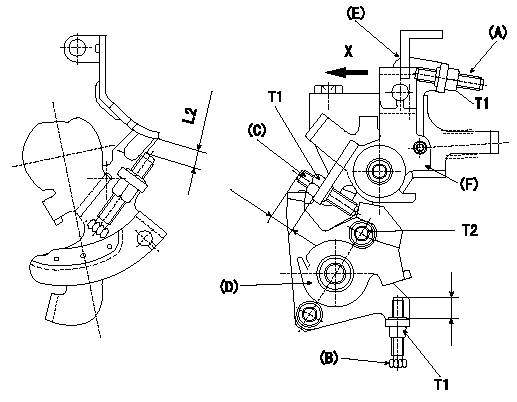
M-CSD adjustment
1. CSD adjustment
Turn the lever (D) clockwise and adjust screw (B) so that the timer piston advance angle is a (L1). Then fix using the nut.
2. With intermediate lever screw (C)'s fixing lever (D) positioned as in 1., pull the intermediate lever in direction X. After confirming that it contacts the stop position, adjust so that screw (C) contacts lever (D) and then fix using the nut.
(Intermediate lever status in 2.: full speed, indicates timer's a advance.
Confirm that the timer piston advances to b deg when the intermediate lever is returned.
3. Fast idle adjustment
Pull the intermediate lever in direction x to contact the stopper and adjust the screw (A) so that the gap between the idle set bracket and the idle screw is L2. Fix using the nut.
The gap between the control lever at the idle position and the screw (A) must be L3.
(E) control lever
(F) intermediate lever
----------
a=3deg b=0deg L1=2.5mm L2=6+-0.05mm L3=(1.7)mm
----------
T1=6~9N-m(0.6~0.9kgf-m) T2=5~7N-m(0.5~0.7kgf-m) L2=6+-0.05mm
----------
a=3deg b=0deg L1=2.5mm L2=6+-0.05mm L3=(1.7)mm
----------
T1=6~9N-m(0.6~0.9kgf-m) T2=5~7N-m(0.5~0.7kgf-m) L2=6+-0.05mm
0000002001 DASHPOT ADJUSTMENT
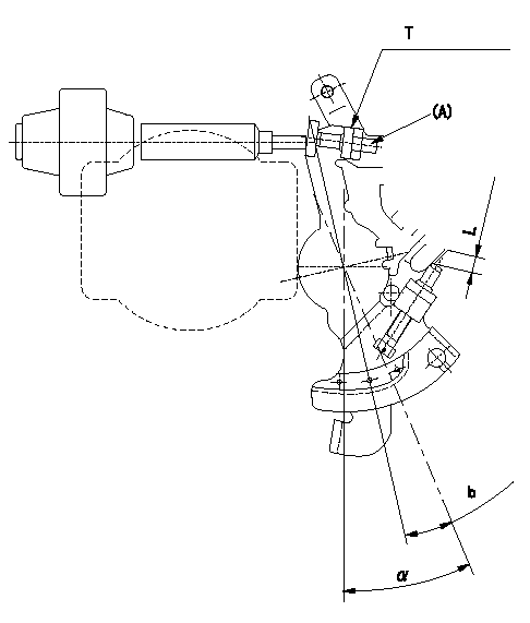
Adjustment of the dash pot
1. Insert a block gauge L (thickness gauge) between the idle set bracket and the idle screw.
2. In the above condition, adjust so that the dashpot adjusting screw (A) contacts the pushrod. Then, fix using the nut.
Record the dashpot return time t.
a = alpha
----------
L=3.8+-0.05mm t=1.8+-0.5sec
----------
T=5.0~7.0N-m{0.5~0.7kgf-m} b=7.4deg L=3.8+-0.05mm
----------
L=3.8+-0.05mm t=1.8+-0.5sec
----------
T=5.0~7.0N-m{0.5~0.7kgf-m} b=7.4deg L=3.8+-0.05mm
Information:
a) Remove by screwing flywheel attaching bolts uniformly into the bolt holes for removal. Pull out using the special tool, Gear Puller. Do not remove the gear by striking it. b) Heat the gear to about 100°C by a heater, etc. Aligning the crankshaft dowel pin with the dowel pin hole in the gear, insert the shaft into the gear, lightly striking the gear end face with a soft hammer.c) Install the sleeve using the special tool, Oil Seal and Sleeve Installer. [Refer to Item (2) - (b), Section 5.1.3.](3) Reassembly Reassembly
(a) Installation of oil jet (excluding 6D14, 6D15) Fix the oil jet aligning with the locating pin and tighten the check valve to specified torque. Bend lock washer onto the check valve to prevent it from turning.(b) Installation of thrust plate and main bearing 1. Install the thrust plate with its side having no oil groove toward the crankcase.2. Line up the lug of main bearing with the lug groove in crankcase. Note that the upper main bearing has an oil hole, which must not be confused with the lower bearing.3. Apply engine oil to all sliding surfaces.(c) Installation of main bearing cap 1) Fit the lower main bearing into the main bearing cap. At the time, make sure that the main bearing lug is aligned with the main bearing cap lug groove.2) Install also the thrust plate onto the main bearing cap in the rear-end position.3) Make sure that the main bearing cap lug groove and crankcase lug groove are on the same side. 1. Face the side of thrust plate having no oil groove toward the rear end of the crankcase and toward the main bearing cap.2. Use thrust plates of the same size for the rear end of the crankcase and main bearing cap rear end. 4) Tighten the main bearing cap bolt to specification. Then, make sure that the crankshaft turns smoothly by hand.5) Measure the crankshaft end play to determine if it is within the nominal value [Refer to Item (1) - (c), Section 5.1.4.].(d) Reassembly of piston and connecting rod 1) Assemble the piston and the connecting rod, ensuring correct direction as illustrated.2) Insert the piston pin to couple the piston and connecting rod. Mount the snap ring to hold the piston pin in position. The piston pin is a clearance fit in the piston. If the piston pin is hard to fit, heat the piston with a piston heater or hot water. 1. Keep the piston weight difference for one engine within 10 g.2. Use connecting rod assembly of same weight mark for an engine.3. Check to see that the size mark of the piston is same as that of the cylinder liner.4. Apply engine oil to sliding surfaces. 3) The connecting rod bolts do not normally need removal; however, where replacement is necessary for damaged bolt, install new bolts by using the following procedures. Make sure that the connecting rod bolt hole is free from damage and burrs. Then,
(a) Installation of oil jet (excluding 6D14, 6D15) Fix the oil jet aligning with the locating pin and tighten the check valve to specified torque. Bend lock washer onto the check valve to prevent it from turning.(b) Installation of thrust plate and main bearing 1. Install the thrust plate with its side having no oil groove toward the crankcase.2. Line up the lug of main bearing with the lug groove in crankcase. Note that the upper main bearing has an oil hole, which must not be confused with the lower bearing.3. Apply engine oil to all sliding surfaces.(c) Installation of main bearing cap 1) Fit the lower main bearing into the main bearing cap. At the time, make sure that the main bearing lug is aligned with the main bearing cap lug groove.2) Install also the thrust plate onto the main bearing cap in the rear-end position.3) Make sure that the main bearing cap lug groove and crankcase lug groove are on the same side. 1. Face the side of thrust plate having no oil groove toward the rear end of the crankcase and toward the main bearing cap.2. Use thrust plates of the same size for the rear end of the crankcase and main bearing cap rear end. 4) Tighten the main bearing cap bolt to specification. Then, make sure that the crankshaft turns smoothly by hand.5) Measure the crankshaft end play to determine if it is within the nominal value [Refer to Item (1) - (c), Section 5.1.4.].(d) Reassembly of piston and connecting rod 1) Assemble the piston and the connecting rod, ensuring correct direction as illustrated.2) Insert the piston pin to couple the piston and connecting rod. Mount the snap ring to hold the piston pin in position. The piston pin is a clearance fit in the piston. If the piston pin is hard to fit, heat the piston with a piston heater or hot water. 1. Keep the piston weight difference for one engine within 10 g.2. Use connecting rod assembly of same weight mark for an engine.3. Check to see that the size mark of the piston is same as that of the cylinder liner.4. Apply engine oil to sliding surfaces. 3) The connecting rod bolts do not normally need removal; however, where replacement is necessary for damaged bolt, install new bolts by using the following procedures. Make sure that the connecting rod bolt hole is free from damage and burrs. Then,