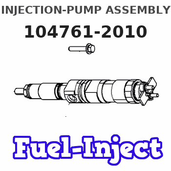
Information injection-pump assembly
ZEXEL
104761-2010
1047612010
Rating:
Cross reference number
ZEXEL
104761-2010
1047612010
Zexel num
Bosch num
Firm num
Name
104761-2010
INJECTION-PUMP ASSEMBLY
Calibration Data:
Adjustment conditions
Test oil
1404 Test oil ISO4113orSAEJ967d
1404 Test oil ISO4113orSAEJ967d
Test oil temperature
degC
45
45
50
Nozzle
105780-0060
Bosch type code
NP-DN0SD1510
Nozzle holder
105780-2150
Opening pressure
MPa
13
13
13.3
Opening pressure
kgf/cm2
133
133
136
Injection pipe
157805-7320
Injection pipe
Inside diameter - outside diameter - length (mm) mm 2-6-450
Inside diameter - outside diameter - length (mm) mm 2-6-450
Joint assembly
157641-4720
Tube assembly
157641-4020
Transfer pump pressure
kPa
20
20
20
Transfer pump pressure
kgf/cm2
0.2
0.2
0.2
Direction of rotation (viewed from drive side)
Right R
Right R
Injection timing adjustment
Pump speed
r/min
600
600
600
Boost pressure
kPa
0
0
0
Boost pressure
mmHg
0
0
0
Average injection quantity
mm3/st.
33.6
33.2
34
Difference in delivery
mm3/st.
2
Basic
*
Oil temperature
degC
50
48
52
Remarks
NA
NA
Injection timing adjustment_02
Pump speed
r/min
700
700
700
Boost pressure
kPa
28
26.7
29.3
Boost pressure
mmHg
210
200
220
Average injection quantity
mm3/st.
38.6
38.2
39
Difference in delivery
mm3/st.
2
Basic
*
Oil temperature
degC
50
48
52
Remarks
CBS
CBS
Injection timing adjustment_03
Pump speed
r/min
600
600
600
Boost pressure
kPa
0
0
0
Boost pressure
mmHg
0
0
0
Average injection quantity
mm3/st.
33.6
32.7
34.5
Difference in delivery
mm3/st.
2.5
Basic
*
Oil temperature
degC
50
48
52
Injection timing adjustment_04
Pump speed
r/min
700
700
700
Boost pressure
kPa
28
26.7
29.3
Boost pressure
mmHg
210
200
220
Average injection quantity
mm3/st.
38.6
37.7
39.5
Difference in delivery
mm3/st.
2.5
Basic
*
Oil temperature
degC
50
48
52
Injection timing adjustment_05
Pump speed
r/min
1200
1200
1200
Boost pressure
kPa
66.7
65.4
68
Boost pressure
mmHg
500
490
510
Average injection quantity
mm3/st.
46
43.5
48.5
Oil temperature
degC
50
48
52
Injection timing adjustment_06
Pump speed
r/min
1800
1800
1800
Boost pressure
kPa
66.7
65.4
68
Boost pressure
mmHg
500
490
510
Average injection quantity
mm3/st.
45.7
42.7
48.7
Oil temperature
degC
50
48
52
Injection timing adjustment_07
Pump speed
r/min
2200
2200
2200
Boost pressure
kPa
66.7
65.4
68
Boost pressure
mmHg
500
490
510
Average injection quantity
mm3/st.
43.8
40.8
46.8
Oil temperature
degC
52
50
54
Injection timing adjustment_08
Pump speed
r/min
2300
2300
2300
Boost pressure
kPa
66.7
65.4
68
Boost pressure
mmHg
500
490
510
Average injection quantity
mm3/st.
43.5
40
47
Oil temperature
degC
52
50
54
Injection quantity adjustment
Pump speed
r/min
2500
2500
2500
Boost pressure
kPa
66.7
65.4
68
Boost pressure
mmHg
500
490
510
Average injection quantity
mm3/st.
20.5
19.5
21.5
Difference in delivery
mm3/st.
4.5
Basic
*
Oil temperature
degC
55
52
58
Injection quantity adjustment_02
Pump speed
r/min
2500
2500
2500
Boost pressure
kPa
66.7
65.4
68
Boost pressure
mmHg
500
490
510
Average injection quantity
mm3/st.
20.5
19
22
Difference in delivery
mm3/st.
5
Basic
*
Oil temperature
degC
55
52
58
Injection quantity adjustment_03
Pump speed
r/min
2800
2800
2800
Boost pressure
kPa
66.7
65.4
68
Boost pressure
mmHg
500
490
510
Average injection quantity
mm3/st.
3
Oil temperature
degC
55
52
58
Governor adjustment
Pump speed
r/min
375
375
375
Boost pressure
kPa
0
0
0
Boost pressure
mmHg
0
0
0
Average injection quantity
mm3/st.
14
13
15
Difference in delivery
mm3/st.
1.7
Basic
*
Oil temperature
degC
48
46
50
Governor adjustment_02
Pump speed
r/min
375
375
375
Boost pressure
kPa
0
0
0
Boost pressure
mmHg
0
0
0
Average injection quantity
mm3/st.
14
12
16
Difference in delivery
mm3/st.
2.2
Basic
*
Oil temperature
degC
48
46
50
Governor adjustment_03
Pump speed
r/min
800
800
800
Boost pressure
kPa
0
0
0
Boost pressure
mmHg
0
0
0
Average injection quantity
mm3/st.
5
Oil temperature
degC
50
48
52
Boost compensator adjustment
Pump speed
r/min
600
600
600
Boost pressure
kPa
0
0
0
Boost pressure
mmHg
0
0
0
Average injection quantity
mm3/st.
30.3
23.8
36.8
Oil temperature
degC
50
48
52
Lever angle (shim thickness)
mm
5.6
5.55
5.65
Boost compensator adjustment_02
Pump speed
r/min
900
900
900
Boost pressure
kPa
0
0
0
Boost pressure
mmHg
0
0
0
Average injection quantity
mm3/st.
23.9
16.9
30.9
Oil temperature
degC
50
48
52
Lever angle (shim thickness)
mm
5.6
5.55
5.65
Timer adjustment
Pump speed
r/min
100
100
100
Boost pressure
kPa
0
0
0
Boost pressure
mmHg
0
0
0
Average injection quantity
mm3/st.
40
40
Basic
*
Oil temperature
degC
48
46
50
Timer adjustment_02
Pump speed
r/min
100
100
100
Boost pressure
kPa
0
0
0
Boost pressure
mmHg
0
0
0
Average injection quantity
mm3/st.
40
40
Oil temperature
degC
48
46
50
Speed control lever angle
Pump speed
r/min
600
600
600
Boost pressure
kPa
0
0
0
Boost pressure
mmHg
0
0
0
Average injection quantity
mm3/st.
0
0
0
Oil temperature
degC
50
48
52
Remarks
Magnet OFF at full-load position
Magnet OFF at full-load position
Speed control lever angle_02
Pump speed
r/min
375
375
375
Boost pressure
kPa
0
0
0
Boost pressure
mmHg
0
0
0
Average injection quantity
mm3/st.
6
Oil temperature
degC
48
46
50
Remarks
Magnet OFF at idling position
Magnet OFF at idling position
0000000901
Pump speed
r/min
900
900
900
Boost pressure
kPa
66.7
65.4
68
Boost pressure
mmHg
500
490
510
Overflow quantity with S/T OFF
cm3/min
390
260
520
Oil temperature
degC
50
48
52
Remarks
With an O-ring
With an O-ring
Stop lever angle
Pump speed
r/min
900
900
900
Boost pressure
kPa
66.7
65.4
68
Boost pressure
mmHg
500
490
510
Pressure with S/T OFF
kPa
432
403
461
Pressure with S/T OFF
kgf/cm2
4.4
4.1
4.7
Basic
*
Oil temperature
degC
50
48
52
Stop lever angle_02
Pump speed
r/min
900
900
900
Boost pressure
kPa
66.7
65.4
68
Boost pressure
mmHg
500
490
510
Pressure with S/T ON
kPa
353
304
402
Pressure with S/T ON
kgf/cm2
3.6
3.1
4.1
Pressure with S/T OFF
kPa
431
392
470
Pressure with S/T OFF
kgf/cm2
4.4
4
4.8
Basic
*
Oil temperature
degC
50
48
52
Stop lever angle_03
Pump speed
r/min
1200
1200
1200
Boost pressure
kPa
66.7
65.4
68
Boost pressure
mmHg
500
490
510
Pressure with S/T OFF
kPa
490
451
529
Pressure with S/T OFF
kgf/cm2
5
4.6
5.4
Oil temperature
degC
50
48
52
Stop lever angle_04
Pump speed
r/min
2300
2300
2300
Boost pressure
kPa
66.7
65.4
68
Boost pressure
mmHg
500
490
510
Pressure with S/T OFF
kPa
765
726
804
Pressure with S/T OFF
kgf/cm2
7.8
7.4
8.2
Oil temperature
degC
52
50
54
0000001101
Pump speed
r/min
900
900
900
Boost pressure
kPa
66.7
65.4
68
Boost pressure
mmHg
500
490
510
Timer stroke with S/T OFF
mm
3.4
3.2
3.6
Basic
*
Oil temperature
degC
50
48
52
_02
Pump speed
r/min
900
900
900
Boost pressure
kPa
66.7
65.4
68
Boost pressure
mmHg
500
490
510
Timer stroke with S/T ON
mm
1.7
1.3
2.1
Timer stroke with S/T OFF
mm
3.4
3.1
3.7
Basic
*
Oil temperature
degC
50
48
52
_03
Pump speed
r/min
1200
1200
1200
Boost pressure
kPa
66.7
65.4
68
Boost pressure
mmHg
500
490
510
Timer stroke with S/T OFF
mm
5.2
4.8
5.6
Oil temperature
degC
50
48
52
_04
Pump speed
r/min
2300
2300
2300
Boost pressure
kPa
66.7
65.4
68
Boost pressure
mmHg
500
490
510
Timer stroke with S/T OFF
mm
9.8
9.3
10.2
Oil temperature
degC
52
50
54
0000001201
Max. applied voltage
V
8
8
8
Test voltage
V
13
12
14
Timing setting
K dimension
mm
3.3
3.2
3.4
KF dimension
mm
7.22
7.12
7.32
MS dimension
mm
1.8
1.7
1.9
Control lever angle alpha
deg.
23
19
27
Control lever angle beta
deg.
42
37
47
Test data Ex:
0000001801 POTENTIOMETER ADJUSTMENT
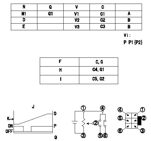
Adjustment of the potentiometer
1. Determine the position of the control lever at the adjusting point. Fix with the dummy bolt contacting the lever.
2. In the fixed position, install the potentiometer so that the output voltage is V1 (supply voltage Vi).
3. After completing potentiometer installation, remove the dummy bolt.
N:Pump speed
Q:Injection quantity
V:Output voltage
P:Boost pressure
A:Adjusting point
B:Checking point
C:Control lever angle
D:Idle lever angle
E:Full speed lever angle
F:Conversion point
G:From idle
H:ON-->OFF
I:OFF-->ON
J:Connecting diagram for the potentiometer
K:Output
O:Output when (2) and (3) connected.
P:When (4) or (6) connected: switch OFF to ON.
Q:When (4) or (6) connected: switch ON to OFF.
----------
V1=3.2+-0.03V Vi=10V
----------
N1=600r/min Q1=16.9+-1.0cm3/1,000st V1=3.2+-0.03V V2=(1.96)V V3=(8.96)V C1=-deg C2=0deg C3=42deg Vi=10V P1=0kPa P2=0mmHg C4=(1.9)deg?@ C5=(22.5++)deg G1=-V G2=-V
----------
V1=3.2+-0.03V Vi=10V
----------
N1=600r/min Q1=16.9+-1.0cm3/1,000st V1=3.2+-0.03V V2=(1.96)V V3=(8.96)V C1=-deg C2=0deg C3=42deg Vi=10V P1=0kPa P2=0mmHg C4=(1.9)deg?@ C5=(22.5++)deg G1=-V G2=-V
0000001901 M-CSD ADJUSTMENT
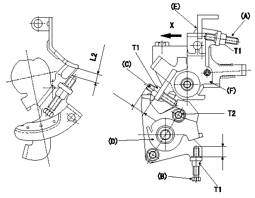
M-CSD adjustment
1. CSD adjustment
Turn the lever (D) clockwise and adjust screw (B) so that the timer piston advance angle is a (L1). Then fix using the nut.
2. With intermediate lever screw (C)'s fixing lever (D) positioned as in 1., pull the intermediate lever in direction X. After confirming that it contacts the stop position, adjust so that screw (C) contacts lever (D) and then fix using the nut.
(Intermediate lever status in 2.: full speed, indicates timer's a advance.
Confirm that the timer piston advances to b deg when the intermediate lever is returned.
3. Fast idle adjustment
Pull the intermediate lever in direction x to contact the stopper and adjust the screw (A) so that the gap between the idle set bracket and the idle screw is L2. Fix using the nut.
The gap between the control lever at the idle position and the screw (A) must be L3.
(E) control lever
(F) intermediate lever
----------
a=3deg b=0deg L1=2.5mm L2=6+-0.05mm L3=(1.7mm)
----------
T1=6~9N-m(0.6~0.9kgf-m) T2=5~7N-m(0.5~0.7kgf-m) L2=6+-0.05mm
----------
a=3deg b=0deg L1=2.5mm L2=6+-0.05mm L3=(1.7mm)
----------
T1=6~9N-m(0.6~0.9kgf-m) T2=5~7N-m(0.5~0.7kgf-m) L2=6+-0.05mm
0000002001 DASHPOT ADJUSTMENT
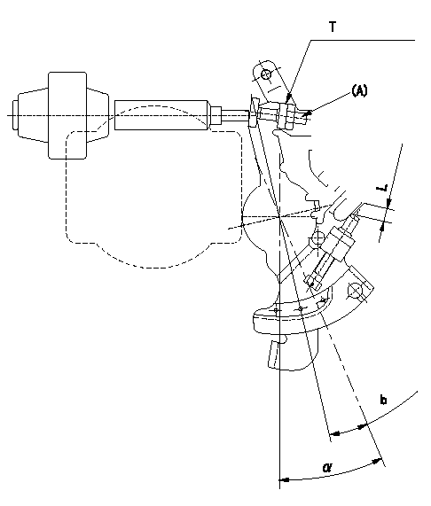
Adjustment of the dash pot
1. Insert a block gauge L (thickness gauge) between the idle set bracket and the idle screw.
2. In the above condition, adjust so that the dashpot adjusting screw (A) contacts the pushrod. Then, fix using the nut.
Record the dashpot return time t.
a = alpha
----------
L=3.8+-0.05mm t=1.8+-0.5sec
----------
T=5.0~7.0N-m(0.5~0.7kgf-m) b=7.4deg L=3.8+-0.05mm(750r/min)
----------
L=3.8+-0.05mm t=1.8+-0.5sec
----------
T=5.0~7.0N-m(0.5~0.7kgf-m) b=7.4deg L=3.8+-0.05mm(750r/min)
Information:
1. External View
(Natural-aspirated engine)
* This photo shows the model 6D14.(Turbocharged engine)
* This photo shows the model 6D14-T.2. Major Specifications
2.1 Major Specifications
2.2 Engine Outputs Classified by Application
1. The output (SAE, gross) is corrected to standard ambient conditions based on SAE J1349.2. The continuous rated output allows 10% (one hour) overload operation.3. Engine Number And Nameplate
(1) Engine number The engine number is stamped on the position as illustrated.Example: The engine number is important in knowing the history of the engine.(2) Nameplate The nameplate is attached to the portion as illustrated.The nameplate bears the followings: 4. General Precautions For Servicing
Before starting the service procedures, check the vehicle for total time driven, use conditions, and user's complaints and requests to know exactly the engine conditions. Record information where necessary.To ensure you are doing correct and efficient service jobs, observe the following precautions: (1) Before performing the service procedures given in this manual, know the trouble spots and isolate the possible cause to determine whether the removal or disassembly procedure is required.(2) Select a flat surface for the service job.(3) When servicing the electrical system, be sure to disconnect the negative cable from the battery.(4) Carefully check parts for oil leaks before cleaning. After cleaning, it may become difficult to spot defective areas.(5) Ready and make the most of the special tools required for servicing. Use the right tools (specified special tools) in the right place to prevent damages to parts and personal injury.(6) Make alignment marks and keep disassembled parts neatly arranged to ensure that they are reassembled into the right positions.* Special care must be taken for assemblies involving a number of parts, similar parts, or parts identical at right- and left-hand sides to ensure correct reassembly.* For alignment and punching markings, select a position that would not mar the appearance and function.* Clearly distinguish parts to be replaced from those reused. (7) The oil seals, packings, O-rings, and other rubber parts, gaskets, and split pins must be replaced with a new one whenever they are removed. For replacement, use Mitsubishi Genuine parts. (8) Apply the specified grease to U-packings, oil seals, dust seals, and bearings before installation.(9) When work requires an assistant or two, always make sure of the safety each other. Never play with switches and levers.(10) Make sure that your shoes are free from grease and oil especially when working on a heavy item.(11) When checking or changing lubricants, wipe off grease and oil from parts immediately with a waste.(12) Special care must be taken in handling sensors and relays which are suspectible to shocks and heat.(13) Use care so that hands and fingers are not injured by sharp edges or corners of the parts.(14) Wear safety goggles whenever handling a grinder or welding machine. Wear gloves as required to ensure utmost safety.5. General Bolts And Nuts Tightening Torque Table
Unless otherwise specified, the parts and equipment of vehicle must be tightened by the following standard bolts and nuts. Tightening torques for these bolts and nuts are shown below.
Have questions with 104761-2010?
Group cross 104761-2010 ZEXEL
104761-2010
INJECTION-PUMP ASSEMBLY