Information injection-pump assembly
ZEXEL
104761-0093
1047610093
Rating:
Cross reference number
ZEXEL
104761-0093
1047610093
Zexel num
Bosch num
Firm num
Name
Calibration Data:
Adjustment conditions
Test oil
1404 Test oil ISO4113orSAEJ967d
1404 Test oil ISO4113orSAEJ967d
Test oil temperature
degC
45
45
50
Nozzle
105000-2010
Bosch type code
NP-DN12SD12TT
Nozzle holder
105780-2080
Opening pressure
MPa
14.7
14.7
15.19
Opening pressure
kgf/cm2
150
150
155
Injection pipe
Inside diameter - outside diameter - length (mm) mm 2-6-840
Inside diameter - outside diameter - length (mm) mm 2-6-840
Transfer pump pressure
kPa
20
20
20
Transfer pump pressure
kgf/cm2
0.2
0.2
0.2
Direction of rotation (viewed from drive side)
Right R
Right R
Injection timing adjustment
Pump speed
r/min
1500
1500
1500
Average injection quantity
mm3/st.
45.7
45.2
46.2
Difference in delivery
mm3/st.
3
Basic
*
Injection timing adjustment_02
Pump speed
r/min
2050
2050
2050
Average injection quantity
mm3/st.
15.4
12.4
18.4
Injection timing adjustment_03
Pump speed
r/min
1800
1800
1800
Average injection quantity
mm3/st.
42.2
40.2
44.2
Injection timing adjustment_04
Pump speed
r/min
1500
1500
1500
Average injection quantity
mm3/st.
45.7
44.7
46.7
Injection timing adjustment_05
Pump speed
r/min
1000
1000
1000
Average injection quantity
mm3/st.
49.6
47.6
51.6
Injection timing adjustment_06
Pump speed
r/min
500
500
500
Average injection quantity
mm3/st.
42.3
40.3
44.3
Injection quantity adjustment
Pump speed
r/min
2050
2050
2050
Average injection quantity
mm3/st.
15.4
12.4
18.4
Basic
*
Injection quantity adjustment_02
Pump speed
r/min
2150
2150
2150
Average injection quantity
mm3/st.
6
Governor adjustment
Pump speed
r/min
300
300
300
Average injection quantity
mm3/st.
10.3
8.3
12.3
Difference in delivery
mm3/st.
2.5
Basic
*
Governor adjustment_02
Pump speed
r/min
300
300
300
Average injection quantity
mm3/st.
10.3
8.3
12.3
Governor adjustment_03
Pump speed
r/min
500
Average injection quantity
mm3/st.
0
0
0
Timer adjustment
Pump speed
r/min
100
100
100
Average injection quantity
mm3/st.
65
65
Basic
*
Speed control lever angle
Pump speed
r/min
300
300
300
Average injection quantity
mm3/st.
0
0
0
Remarks
Magnet OFF
Magnet OFF
0000000901
Pump speed
r/min
1500
1500
1500
Overflow quantity
cm3/min
399.9
270
529.8
Stop lever angle
Pump speed
r/min
1500
1500
1500
Pressure
kPa
598.5
569
628
Pressure
kgf/cm2
6.1
5.8
6.4
Basic
*
Stop lever angle_02
Pump speed
r/min
500
500
500
Pressure
kPa
225.5
196
255
Pressure
kgf/cm2
2.3
2
2.6
Stop lever angle_03
Pump speed
r/min
1000
1000
1000
Pressure
kPa
411.5
382
441
Pressure
kgf/cm2
4.2
3.9
4.5
Stop lever angle_04
Pump speed
r/min
1500
1500
1500
Pressure
kPa
598.5
569
628
Pressure
kgf/cm2
6.1
5.8
6.4
Stop lever angle_05
Pump speed
r/min
1800
1800
1800
Pressure
kPa
706
677
735
Pressure
kgf/cm2
7.2
6.9
7.5
0000001101
Pump speed
r/min
1500
1500
1500
Timer stroke
mm
5.7
5.5
5.9
Basic
*
_02
Pump speed
r/min
1000
1000
1000
Timer stroke
mm
2.8
2.2
3.4
_03
Pump speed
r/min
1500
1500
1500
Timer stroke
mm
5.7
5.4
6
_04
Pump speed
r/min
1800
1800
1800
Timer stroke
mm
7.45
6.9
8
0000001201
Max. applied voltage
V
16
16
16
Test voltage
V
25
24
26
0000001501
Pump speed
r/min
1000
1000
1000
Atmospheric pressure difference
kPa
-21.9
-21.9
-21.9
Atmospheric pressure difference
mmHg
-164
-164
-164
Average injection quantity
mm3/st.
41.5
40.5
42.5
Basic
*
_02
Pump speed
r/min
1000
1000
1000
Atmospheric pressure difference
kPa
-21.9
-21.9
-21.9
Atmospheric pressure difference
mmHg
-164
-164
-164
Average injection quantity
mm3/st.
41.5
40
43
Timing setting
K dimension
mm
3.3
3.2
3.4
KF dimension
mm
5.8
5.7
5.9
MS dimension
mm
1.8
1.7
1.9
Pre-stroke
mm
0.1
0.08
0.12
Control lever angle alpha
deg.
20
16
24
Control lever angle beta
deg.
40
32
48
Test data Ex:
0000001501 ANEROID COMPENSATOR
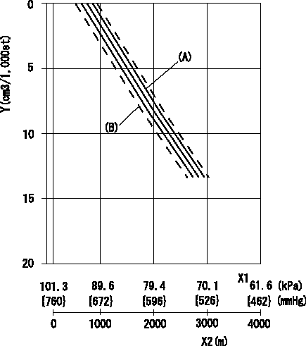
ACS adjustment
Full load injection quantity at high altitudes and ACS adjusting method
1. Full load injection quantity adjustment
(1)Remove the ACS cover and remove the bellows and adjusting shim.
(2)Perform all adjustments as per the adjustment standard except for ACS adjustment.
2. ACS adjustment
(1)Assemble the ACS cover, bellows and adjusting shim.
(2)At pump speed N1, adjust using a shim to obtain the decrease for the altitude shown in the table.
X1 = atmospheric pressure
X2 = altitude
Y = decrease quantity
(A) = adjustment value
(B) = test value
----------
N1=1000r/min
----------
----------
N1=1000r/min
----------
0000001801 MICROSWITCH ADJUSTMENT
Microswitch adjustment
With the clearance between the idle stopper bolt (set at the idle setting) and the control lever set at L, adjust the control lever adjusting screw so that it contacts the head of the microswitch plunger.
----------
L=3.9+-0.2mm
----------
----------
L=3.9+-0.2mm
----------
Information:
1. Remove the fuel injection lines. It is not necessary to remove the fuel transfer pump, the fuel injection pump housing and governor to remove the fuel injection pumps. 2. Remove cover (1). 3. Move the rack until tool (A) can be installed to hold the rack in the center position. The rack must be in the center position to remove the fuel injection pumps.4. Use tool (B) to remove bushing (2). 5. Install tool (C) on the bonnet and remove the fuel injection pump. 6. Remove spacer (3) from the fuel injection pump housing. Spacers (3) are the same thickness for each fuel injection pump so they can be mixed. The fuel injection pump plungers and barrels are sets and can not be mixed.Install Fuel Injection Pumps
1. Install spacer (1) in the fuel injection pump housing. 2. Move the rack until tool (A) can be installed to hold the rack in the center position. The rack must be in the center position to install the fuel injection pumps.3. Turn the camshaft until the lobe of the camshaft is down for the pump to be installed. 4. Install tool (B) on the bonnet of the fuel injection pump. Put clean oil on O-ring seal (4) and install the O-ring seal and bushing (5) over tool (B) as shown. 5. Install the fuel injection pump in the pump housing with saw cut (slot) (3) in the gear in alignment with small pin (2) in the lifter assembly and groove (7) in the barrel in alignment with large pin (6) in the pump housing.6. Push down on tool (B) and tighten bushing (5) by hand until the bushing is even with the top of the housing. If installation of the bushing can not be made this far by hand, remove it. Remove the pump, put the parts in alignment again and install the bushing again.
If installation of pump is correct, the bushing can be tightened by hand until it is even with the face of the pump housing.
7. Remove tool (B) and install tool (C) in the bushing. Use tool (C) and a torque wrench to tighten the bushing to a torque of 165 14 N m (120 10 lb. ft.).8. Remove tools (C) and (A). Install the cover on the fuel injection pump housing.9. Install the fuel injection lines. Tighten the fuel injection line nuts to a torque of 41 7 N m (30 5 lb.ft.).Disassemble Fuel Injection Pumps
start by:a) remove fuel injection pumps
Be careful when the injection pumps are disassembled. Do not damage the surfaces of the plungers, barrels and bonnets. Any scratches will cause leakage inside the fuel injection pump. The plunger and barrel for each pump are made as a set. Do not put the plunger of one pump in the barrel of another pump. If one part has wear, install a complete new pump assembly. Be careful when the plunger is put into the bore of the barrel.
1. Pull plunger (1)