Information injection-pump assembly
ZEXEL
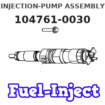
104761-0030
1047610030
MAZDA
487213800E
487213800e
Rating:
Components :
| 0. | INJECTION-PUMP ASSEMBLY | 104761-0030 |
| 1. | _ | |
| 2. | FUEL INJECTION PUMP | |
| 3. | NUMBER PLATE | 146634-2500 |
| 4. | _ | |
| 5. | CAPSULE | |
| 6. | ADJUSTING DEVICE | |
| 7. | NOZZLE AND HOLDER ASSY | 105101-1970 |
| 8. | Nozzle and Holder | 4874 13 640 |
| 9. | Open Pre:MPa(Kqf/cm2) | 13.2{135} |
| 10. | NOZZLE-HOLDER | 105031-1610 |
| 11. | NOZZLE | 105000-1030 |
Scheme ###:
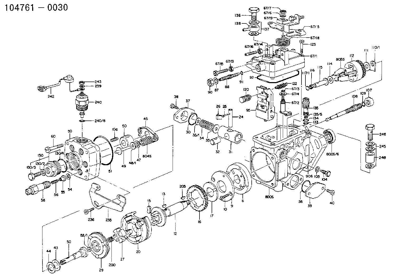
| 1. | [1] | 146007-0420 | PUMP HOUSING |
| 1/6. | [1] | 146601-0000 | PACKING RING |
| 6. | [1] | 146100-0020 | SUPPLY PUMP D17 |
| 9. | [1] | 146103-0000 | COVER |
| 10. | [2] | 139104-0000 | FLAT-HEAD SCREW |
| 12. | [1] | 146200-0000 | DRIVE SHAFT |
| 13. | [1] | 146201-0000 | WOODRUFF KEY |
| 15. | [2] | 146202-0001 | DAMPER |
| 16. | [1] | 146203-0000 | TOOTHED GEAR |
| 17. | [1] | 146204-0000 | PLAIN WASHER |
| 20. | [1] | 146210-0020 | ROLLER SET |
| 24. | [1] | 146303-0000 | BEARING PIN |
| 25. | [1] | 146304-0000 | BEARING PIN |
| 26. | [1] | 146305-0000 | CLAMPING BAND |
| 27. | [1] | 146205-0000 | SLOTTED WASHER |
| 29. | [1] | 146221-0220 | CAM PLATE '02' |
| 30. | [1] | 146600-0800 | O-RING |
| 31. | [1] | 146300-0500 | PUMP PLUNGER ' 5' 5-9.0 |
| 32. | [1] | 146301-0000 | SLIDING PIECE |
| 33. | [1] | 146603-0700 | SHIM |
| 34. | [1] | 146302-0000 | COMPRESSION SPRING K=2.05 |
| 35. | [1] | 029998-0710 | SHIM |
| 35/1. | [0] | 146603-0700 | SHIM |
| 35/1. | [0] | 146603-0800 | SHIM |
| 35/1. | [0] | 146603-0900 | SHIM |
| 35/1. | [0] | 146603-1000 | SHIM |
| 35/1. | [0] | 146603-1100 | SHIM |
| 36. | [1] | 146600-0800 | O-RING |
| 37. | [1] | 146310-0000 | COVER |
| 38. | [2] | 139106-0000 | FLAT-HEAD SCREW |
| 39. | [1] | 146310-0100 | COVER |
| 40. | [2] | 139106-0000 | FLAT-HEAD SCREW |
| 43. | [1] | 146230-0000 | SHIM |
| 44. | [1] | 146230-0100 | PLAIN WASHER |
| 45. | [1] | 146231-0000 | SLOTTED WASHER |
| 47. | [2] | 146233-0000 | SLOTTED WASHER |
| 48. | [2] | 029998-0570 | SHIM |
| 48/1. | [2] | 146603-0000 | SHIM |
| 48/1. | [2] | 146603-0100 | SHIM |
| 48/1. | [2] | 146603-0200 | SHIM |
| 48/1. | [2] | 146603-0300 | SHIM |
| 48/1. | [2] | 146603-0400 | SHIM |
| 48/1. | [2] | 146603-0500 | SHIM |
| 48/1. | [2] | 146603-0600 | SHIM |
| 49. | [2] | 146234-0020 | GUIDE PIN |
| 50. | [1] | 146405-0520 | HYDRAULIC HEAD |
| 50. | [1] | 146405-0520 | HYDRAULIC HEAD |
| 50. | [1] | 146405-0520 | HYDRAULIC HEAD |
| 51. | [1] | 146600-0000 | O-RING |
| 52. | [1] | 029998-0300 | SHIM |
| 52/1. | [1] | 146420-0000 | SHIM |
| 52/1. | [1] | 146420-0100 | SHIM |
| 52/1. | [1] | 146420-0200 | SHIM |
| 52/1. | [1] | 146420-0300 | SHIM |
| 52/1. | [1] | 146420-0400 | SHIM |
| 52/1. | [1] | 146420-0500 | SHIM |
| 52/1. | [1] | 146420-0600 | SHIM |
| 52/1. | [1] | 146420-0700 | SHIM |
| 52/1. | [1] | 146420-0800 | SHIM |
| 52/1. | [1] | 146420-0900 | SHIM |
| 52/1. | [1] | 146420-1000 | SHIM |
| 52/1. | [1] | 146420-1100 | SHIM |
| 52/1. | [1] | 146420-1200 | SHIM |
| 52/1. | [1] | 146420-1300 | SHIM |
| 52/1. | [1] | 146420-1400 | SHIM |
| 52/1. | [1] | 146420-1500 | SHIM |
| 52/1. | [1] | 146420-1600 | SHIM |
| 52/1. | [1] | 146420-1700 | SHIM |
| 52/1. | [1] | 146420-1800 | SHIM |
| 52/1. | [1] | 146420-1900 | SHIM |
| 52/1. | [1] | 146420-2000 | SHIM |
| 52/1. | [1] | 146420-2100 | SHIM |
| 52/1. | [1] | 146420-2200 | SHIM |
| 52/1. | [1] | 146420-2300 | SHIM |
| 52/1. | [1] | 146420-2400 | SHIM |
| 52/1. | [1] | 146420-2500 | SHIM |
| 52/1. | [1] | 146420-2600 | SHIM |
| 52/1. | [1] | 146420-2700 | SHIM |
| 52/1. | [1] | 146420-2800 | SHIM |
| 52/1. | [1] | 146420-2900 | SHIM |
| 52/1. | [1] | 146420-3000 | SHIM |
| 52/1. | [1] | 146420-3100 | SHIM |
| 52/1. | [1] | 146420-3200 | SHIM |
| 52/1. | [1] | 146420-3300 | SHIM |
| 52/1. | [1] | 146420-3400 | SHIM |
| 52/1. | [1] | 146420-3500 | SHIM |
| 52/1. | [1] | 146420-3600 | SHIM |
| 52/1. | [1] | 146420-3700 | SHIM |
| 52/1. | [1] | 146420-3800 | SHIM |
| 52/1. | [1] | 146420-3900 | SHIM |
| 52/1. | [1] | 146420-4000 | SHIM |
| 52/1. | [1] | 146420-4100 | SHIM |
| 52/1. | [1] | 146420-4200 | SHIM |
| 52/1. | [1] | 146420-4300 | SHIM |
| 52/1. | [1] | 146420-4400 | SHIM |
| 52/1. | [1] | 146420-4500 | SHIM |
| 52/1. | [1] | 146420-4600 | SHIM |
| 52/1. | [1] | 146420-4700 | SHIM |
| 52/1. | [1] | 146420-4800 | SHIM |
| 52/1. | [1] | 146420-4900 | SHIM |
| 52/1. | [1] | 146420-5000 | SHIM |
| 52/1. | [1] | 146420-5100 | SHIM |
| 52/1. | [1] | 146420-5200 | SHIM |
| 52/1. | [1] | 146420-5300 | SHIM |
| 52/1. | [1] | 146420-5400 | SHIM |
| 52/1. | [1] | 146420-5500 | SHIM |
| 52/1. | [1] | 146420-5600 | SHIM |
| 52/1. | [1] | 146420-5700 | SHIM |
| 52/1. | [1] | 146420-5800 | SHIM |
| 54. | [6] | 146433-0100 | GASKET |
| 55. | [6] | 146430-1320 | DELIVERY-VALVE ASSEMBLY 'VE14'VR45 |
| 56. | [6] | 146432-0000 | COMPRESSION SPRING K=0.48 |
| 58. | [6] | 146440-0220 | FITTING D0.45 L=50 |
| 60. | [4] | 139106-0100 | FLAT-HEAD SCREW |
| 67. | [1] | 146500-2920 | GOVERNOR COVER |
| 67/1. | [1] | 146505-1220 | GOVERNOR COVER |
| 67/2. | [1] | 146515-0220 | CONTROL SHAFT R20 |
| 67/3. | [1] | 146600-0100 | O-RING |
| 67/4. | [1] | 139310-0200 | PLAIN WASHER |
| 67/5. | [1] | 146530-0400 | CONTROL LEVER |
| 67/5B. | [1] | 146530-0500 | CONTROL LEVER ' 0' |
| 67/6. | [1] | 014110-6440 | LOCKING WASHER |
| 67/7. | [1] | 013020-6040 | UNION NUT |
| 67/13. | [1] | 139206-0000 | UNION NUT |
| 67/14. | [1] | 029240-6010 | UNION NUT |
| 67/15. | [1] | 146526-0300 | BLEEDER SCREW |
| 67/16. | [1] | 146526-0100 | FLAT-HEAD SCREW |
| 67/18. | [1] | 146587-2000 | COILED SPRING |
| 67/19. | [1] | 146541-0000 | ANGLE PIECE |
| 87. | [1] | 139308-0300 | PLAIN WASHER |
| 88. | [1] | 146545-0300 | THREADED PIN |
| 88B. | [1] | 146545-0400 | THREADED PIN |
| 88C. | [1] | 146545-0500 | THREADED PIN |
| 90. | [1] | 139208-0100 | UNION NUT |
| 91. | [1] | 146600-1200 | O-RING |
| 92. | [1] | 146600-1000 | SEAL RING |
| 95. | [1] | 146550-0020 | FULCRUM LEVER I=2.2 |
| 104. | [2] | 146568-0000 | SLOTTED SPRING PIN |
| 105. | [2] | 026508-1140 | GASKET |
| 106. | [2] | 146588-0000 | COILED SPRING |
| 107. | [1] | 146569-0100 | UNION NUT |
| 108. | [1] | 146570-0200 | GOVERNOR SHAFT |
| 109. | [1] | 146600-0400 | O-RING |
| 110. | [1] | 029998-4130 | SHIM |
| 110/1. | [1] | 146571-0000 | SHIM |
| 110/1. | [1] | 146571-0100 | SHIM |
| 110/1. | [1] | 146571-0200 | SHIM |
| 110/1. | [1] | 146571-0300 | SHIM |
| 110/1. | [1] | 146571-0400 | SHIM |
| 110/1. | [1] | 146571-0500 | SHIM |
| 110/1. | [1] | 146571-0600 | SHIM |
| 110/1. | [1] | 146571-0700 | SHIM |
| 110/1. | [1] | 146571-0800 | SHIM |
| 111. | [1] | 146602-0600 | PLAIN WASHER |
| 112. | [1] | 146572-0120 | FLYWEIGHT ASSEMBLY |
| 114. | [1] | 146602-0500 | PLAIN WASHER |
| 115. | [1] | 146575-0000 | SLIDING SLEEVE D2.0 |
| 116. | [1] | 146576-0000 | SEALING CAP |
| 117. | [1] | 029998-5460 | PLUG |
| 117/1. | [1] | 146577-0000 | PLUG |
| 117/1. | [1] | 146577-0100 | PLUG |
| 117/1. | [1] | 146577-0200 | PLUG |
| 117/1. | [1] | 146577-0300 | PLUG |
| 117/1. | [1] | 146577-0400 | PLUG |
| 117/1. | [1] | 146577-0500 | PLUG |
| 117/1. | [1] | 146577-0600 | PLUG |
| 117/1. | [1] | 146577-0700 | PLUG |
| 117/1. | [1] | 146577-0800 | PLUG |
| 117/1. | [1] | 146577-0900 | PLUG |
| 117/1. | [1] | 146577-1000 | PLUG |
| 117/1. | [1] | 146577-1100 | PLUG |
| 117/1. | [1] | 146577-1200 | PLUG |
| 117/1. | [1] | 146577-1300 | PLUG |
| 117/1. | [1] | 146577-1400 | PLUG |
| 117/1. | [1] | 146577-1500 | PLUG |
| 117/1. | [1] | 146577-1600 | PLUG |
| 117/1. | [1] | 146577-1700 | PLUG |
| 120. | [1] | 146579-0020 | RETAINING PIN |
| 122. | [1] | 146580-2100 | GOVERNOR SPRING K=0.104 |
| 123. | [4] | 139106-0200 | FLAT-HEAD SCREW |
| 130. | [1] | 146421-0220 | CAPSULE D14 ZB |
| 130/2. | [1] | 026508-1140 | GASKET |
| 130/3. | [1] | 146422-0200 | BLEEDER SCREW |
| 130/4. | [1] | 146600-0500 | O-RING |
| 133. | [1] | 146600-0600 | O-RING |
| 134. | [1] | 146600-0700 | O-RING |
| 135. | [1] | 146110-0620 | CONTROL VALVE '06'2XD1.6K=2.0 |
| 135/5. | [1] | 146114-0000 | SPRING WASHER |
| 136. | [1] | 146120-0020 | OVER FLOW VALVE |
| 137. | [2] | 026512-1840 | GASKET |
| 138. | [1] | 146610-0020 | INLET UNION OUT B1 |
| 200. | [1] | 146206-0100 | COILED SPRING |
| 235. | [1] | 146612-1100 | BRACKET |
| 236. | [2] | 139106-0500 | FLAT-HEAD SCREW |
| 239. | [1] | 023500-5140 | PLAIN WASHER |
| 240. | [1] | 146650-0720 | PULLING ELECTROMAGNET |
| 240/8. | [1] | 146600-1700 | O-RING |
| 242. | [1] | 146658-0720 | WIRE ' 7' 12V |
| 243. | [1] | 013020-5240 | UNION NUT |
| 245. | [3] | 026512-1840 | GASKET |
| 246. | [1] | 139812-0400 | EYE BOLT |
| 248. | [1] | 146614-0100 | SPACER BUSHING |
| 800S. | [1] | 146009-0920 | PUMP HOUSING |
| 800S/1. | [1] | 146007-0420 | PUMP HOUSING |
| 800S/1/6. | [1] | 146601-0000 | PACKING RING |
| 804S. | [1] | 146232-0220 | COMPRESSION SPRING |
| 805S. | [1] | 146574-0120 | PARTS SET |
| 810S. | [1] | 146600-2420 | REPAIR SET |
| 906. | [1] | 146634-2500 | NUMBER PLATE |
Include in #2:
104761-0030
as INJECTION-PUMP ASSEMBLY
Cross reference number
ZEXEL
104761-0030
1047610030
MAZDA
487213800E
487213800e
Zexel num
Bosch num
Firm num
Name
Calibration Data:
Adjustment conditions
Test oil
1404 Test oil ISO4113orSAEJ967d
1404 Test oil ISO4113orSAEJ967d
Test oil temperature
degC
45
45
50
Nozzle
105000-2010
Bosch type code
NP-DN12SD12TT
Nozzle holder
105780-2080
Opening pressure
MPa
14.7
14.7
15.19
Opening pressure
kgf/cm2
150
150
155
Injection pipe
Inside diameter - outside diameter - length (mm) mm 2-6-840
Inside diameter - outside diameter - length (mm) mm 2-6-840
Transfer pump pressure
kPa
20
20
20
Transfer pump pressure
kgf/cm2
0.2
0.2
0.2
Direction of rotation (viewed from drive side)
Right R
Right R
Injection timing adjustment
Pump speed
r/min
800
800
800
Average injection quantity
mm3/st.
48.2
47.7
48.7
Difference in delivery
mm3/st.
3.5
Basic
*
Oil temperature
degC
50
48
52
Injection timing adjustment_02
Pump speed
r/min
800
800
800
Average injection quantity
mm3/st.
48.2
47.2
49.2
Difference in delivery
mm3/st.
4
Oil temperature
degC
50
48
52
Injection timing adjustment_03
Pump speed
r/min
1200
1200
1200
Average injection quantity
mm3/st.
48.4
46.8
50
Oil temperature
degC
50
48
52
Injection quantity adjustment
Pump speed
r/min
1325
1325
1325
Average injection quantity
mm3/st.
20.2
17.2
23.2
Difference in delivery
mm3/st.
4
Basic
*
Oil temperature
degC
50
48
52
Injection quantity adjustment_02
Pump speed
r/min
1400
1400
1400
Average injection quantity
mm3/st.
6
Oil temperature
degC
50
48
52
Injection quantity adjustment_03
Pump speed
r/min
1325
1325
1325
Average injection quantity
mm3/st.
20.2
17.2
23.2
Oil temperature
degC
50
48
52
Governor adjustment
Pump speed
r/min
300
300
300
Average injection quantity
mm3/st.
10.2
8.2
12.2
Difference in delivery
mm3/st.
3.5
Basic
*
Oil temperature
degC
48
46
50
Governor adjustment_02
Pump speed
r/min
300
300
300
Average injection quantity
mm3/st.
10.2
8.2
12.2
Difference in delivery
mm3/st.
3
Oil temperature
degC
48
46
50
Timer adjustment
Pump speed
r/min
100
100
100
Average injection quantity
mm3/st.
65
65
Basic
*
Oil temperature
degC
48
46
50
Speed control lever angle
Pump speed
r/min
300
300
300
Average injection quantity
mm3/st.
0
0
0
Oil temperature
degC
48
46
50
Remarks
Magnet OFF at idling position
Magnet OFF at idling position
0000000901
Pump speed
r/min
800
800
800
Overflow quantity
cm3/min
420
290
550
Oil temperature
degC
50
48
52
Stop lever angle
Pump speed
r/min
800
800
800
Pressure
kPa
500
471
529
Pressure
kgf/cm2
5.1
4.8
5.4
Basic
*
Oil temperature
degC
50
48
52
Stop lever angle_02
Pump speed
r/min
800
800
800
Pressure
kPa
500.5
471
530
Pressure
kgf/cm2
5.1
4.8
5.4
Oil temperature
degC
50
48
52
Stop lever angle_03
Pump speed
r/min
1200
1200
1200
Pressure
kPa
657
628
686
Pressure
kgf/cm2
6.7
6.4
7
Oil temperature
degC
50
48
52
0000001101
Pump speed
r/min
800
800
800
Timer stroke
mm
2.5
2.3
2.7
Basic
*
Oil temperature
degC
50
48
52
_02
Pump speed
r/min
800
800
800
Timer stroke
mm
2.5
2.3
2.7
Oil temperature
degC
50
48
52
_03
Pump speed
r/min
1200
1200
1200
Timer stroke
mm
6.5
6.1
6.9
Oil temperature
degC
50
48
52
0000001201
Max. applied voltage
V
8
8
8
Test voltage
V
13
12
14
Timing setting
K dimension
mm
3.3
3.2
3.4
KF dimension
mm
5.8
5.7
5.9
MS dimension
mm
1.8
1.7
1.9
Control lever angle alpha
deg.
10
6
14
Control lever angle beta
deg.
34
30
38
Information:
Coolant is essential to control engine operating temperatures and make components last longer. Poorly maintained coolant can actually shorten component life by causing a chain reaction of heat problems. Excessive heat can cause: * Hot spots that crack steel, notably in cylinder heads* Bubble pockets that form on cylinder surfaces and result in liner pitting* Oil to degrade, leading to component damage* Lacquer and shellac build up on precision hydraulic parts* Oil additives to break down and transmission clutches to slipS O S Coolant Analysis is the best way to monitor the condition of your coolant and your cooling system. The two level program, based on samples you submit, shows the condition of coolant and the cooling system.Level I: Basic Coolant Maintenance Check
Checks for correct chemical balance for proper heat and corrosion control. Tests for: * glycol* SCA concentrations* pH* conductivityS O S Coolant Analysis reports results and makes recommendations, usually within 24 hours.The concentration of SCA should be checked regularly for overconcentration or underconcentration. This should be done with test kits, or S O S Coolant Analysis (Level I) at the Every 250 Service Hours interval.Further coolant analysis is recommended at twice a year or after every 1000 service hours.For example, suppose considerable deposits are found in the water jacket areas on the external cooling system, yet coolant additive concentrations were carefully maintained. Chances are that the coolant water had minerals which deposited on the engine over time.One way to verify the water condition, or to be sure of new water at fill time, is to have a coolant analysis conducted. Full water analysis can sometimes be obtained locally by contacting your local water utility company or an agricultural agent. Private laboratories are also available.Caterpillar recommends S O S Level II Coolant Analysis.Level II: Comprehensive Cooling System Analysis
Completely analyzes coolant and coolant effects on the cooling system. Level II Analysis provides: * full Level I analysis* visual properties inspection* metal corrosion and contaminant identification* identification of built up impurities that point to corrosion and scaling problems BEFORE they lead to costly repairs.Level II Analysis provides a simple, clear report of results, and makes recommendations for the lowest cost corrective options.For more information of coolant analysis and how it can help manage your equipment, see your Caterpillar dealer. Consult your Caterpillar dealer for complete information and assistance in establishing an S O S analysis program for your engine(s).