Information injection-pump assembly
BOSCH
9 460 613 188
9460613188
ZEXEL
104760-4830
1047604830
NISSAN-DIESEL
16700WJ012
16700wj012
Rating:
Components :
| 0. | INJECTION-PUMP ASSEMBLY | 104760-4830 |
| 1. | _ | |
| 2. | FUEL INJECTION PUMP | 104660-4830 |
| 3. | NUMBER PLATE | |
| 4. | _ | |
| 5. | CAPSULE | |
| 6. | ADJUSTING DEVICE | |
| 7. | NOZZLE AND HOLDER ASSY | 105148-1121 |
| 8. | Nozzle and Holder | 16600-43G03 |
| 9. | Open Pre:MPa(Kqf/cm2) | 9.8{100} |
| 10. | NOZZLE-HOLDER | 105078-0050 |
| 11. | NOZZLE | 105007-1130 |
Scheme ###:
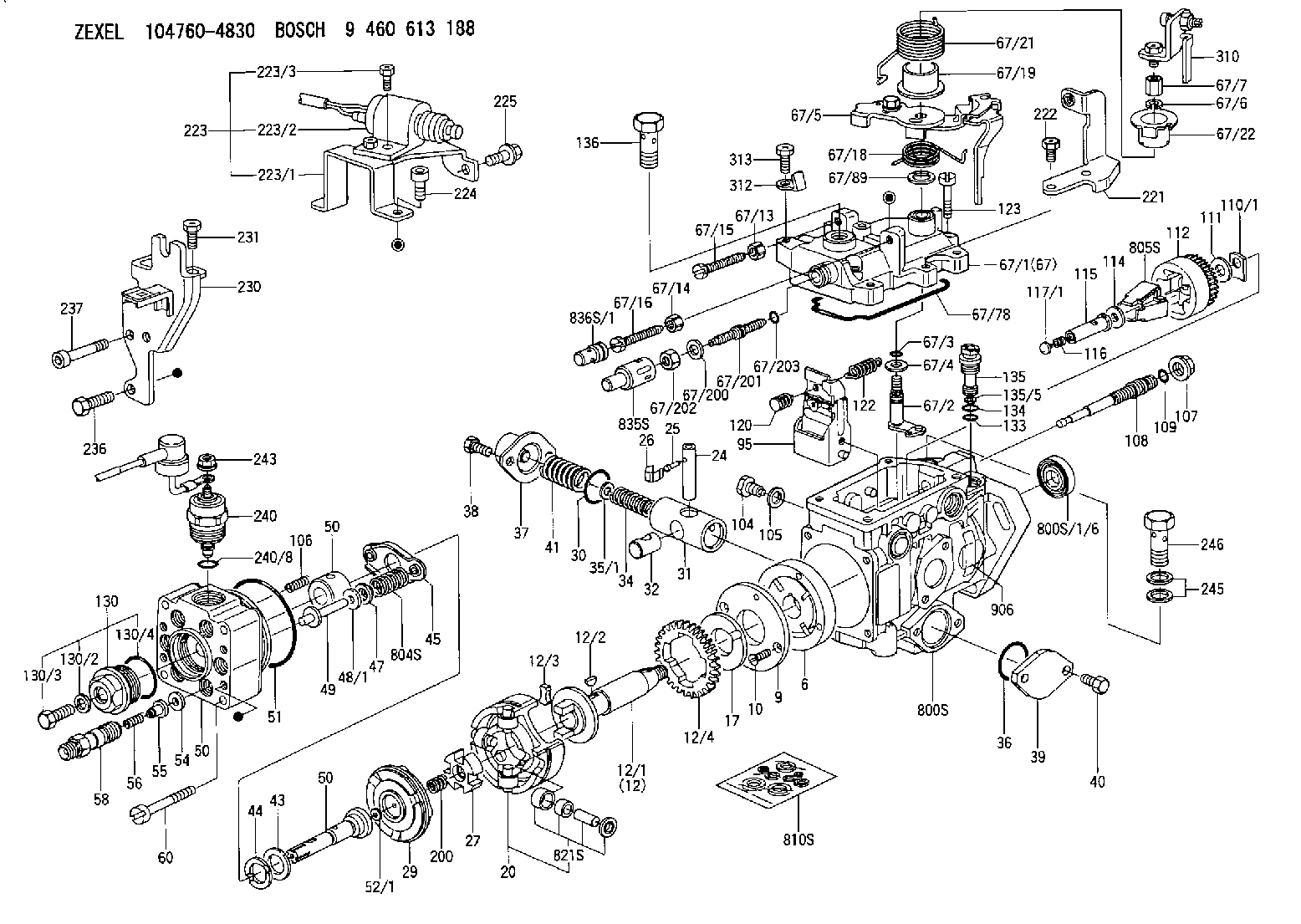
| 1/6. | [1] | 146601-0900 | PACKING RING |
| 6. | [1] | 146100-0420 | SUPPLY PUMP |
| 9. | [1] | 146103-0100 | COVER |
| 10. | [2] | 139104-0000 | FLAT-HEAD SCREW |
| 12. | [1] | 146200-0020 | DRIVE SHAFT |
| 12/1. | [1] | 146200-0000 | DRIVE SHAFT |
| 12/2. | [1] | 146201-0000 | WOODRUFF KEY |
| 12/3. | [2] | 146202-0100 | DAMPER |
| 12/4. | [1] | 146203-0000 | TOOTHED GEAR |
| 17. | [1] | 146204-0000 | PLAIN WASHER |
| 20. | [1] | 146210-2720 | ROLLER SET |
| 24. | [1] | 146303-0000 | BEARING PIN |
| 25. | [1] | 146304-0000 | BEARING PIN |
| 26. | [1] | 146305-0000 | CLAMPING BAND |
| 27. | [1] | 146205-0000 | SLOTTED WASHER |
| 29. | [1] | 146221-0920 | CAM PLATE |
| 30. | [1] | 146600-0800 | O-RING |
| 31. | [1] | 146311-6420 | PUMP PLUNGER |
| 32. | [1] | 146301-0000 | SLIDING PIECE |
| 34. | [1] | 146312-3700 | COMPRESSION SPRING |
| 34B. | [1] | 146312-1800 | COMPRESSION SPRING |
| 34C. | [1] | 146312-3400 | COMPRESSION SPRING |
| 35/1. | [1] | 146690-3200 | SHIM D11.5&9.4T0.1 |
| 35/1. | [1] | 146690-3300 | SHIM D11.5&9.4T0.2 |
| 35/1. | [1] | 146690-3400 | SHIM D11.5&9.4T0.25 |
| 35/1. | [1] | 146690-3500 | SHIM D11.5&9.4T1.0 |
| 35/1. | [1] | 146690-4100 | SHIM D11.5&9.4T2 |
| 35/1. | [1] | 146690-4200 | SHIM D11.5&9.4T0.5 |
| 35/1. | [1] | 146690-4300 | SHIM D11.5&9.4T0.75 |
| 36. | [1] | 146600-0800 | O-RING |
| 37. | [1] | 146310-4020 | COVER |
| 38. | [2] | 146620-5000 | BLEEDER SCREW |
| 39. | [1] | 146310-0100 | COVER |
| 40. | [2] | 146620-5000 | BLEEDER SCREW |
| 41. | [1] | 146312-1900 | COMPRESSION SPRING |
| 43. | [1] | 146230-0000 | SHIM |
| 44. | [1] | 146230-0100 | PLAIN WASHER |
| 45. | [1] | 146231-0001 | SLOTTED WASHER |
| 47. | [2] | 146233-0000 | SLOTTED WASHER |
| 48/1. | [1] | 146603-0400 | SHIM D17.0&5.2T1.50 |
| 48/1. | [1] | 146603-0500 | SHIM D17.0&5.2T1.80 |
| 48/1. | [1] | 146603-0600 | SHIM D17.0&5.2T2.00 |
| 48/1. | [1] | 146690-1700 | SHIM D17&5.2T1.4 |
| 48/1. | [1] | 146690-1800 | SHIM D17&5.2T1.6 |
| 48/1. | [1] | 146690-1900 | SHIM D17&5.2T1.7 |
| 49. | [2] | 146234-0500 | GUIDE PIN |
| 50. | [1] | 146405-1920 | HYDRAULIC HEAD |
| 50. | [1] | 146405-1920 | HYDRAULIC HEAD |
| 50. | [1] | 146405-1920 | HYDRAULIC HEAD |
| 51. | [1] | 146600-0000 | O-RING |
| 52/1. | [1] | 146420-0200 | SHIM D9.5&3.0T1.94 |
| 52/1. | [1] | 146420-0700 | SHIM D9.5&3.0T2.04 |
| 52/1. | [1] | 146420-1200 | SHIM D9.5&3.0T2.14 |
| 52/1. | [1] | 146420-1700 | SHIM D9.5&3.0T2.24 |
| 52/1. | [1] | 146420-2200 | SHIM D9.5&3.0T2.34 |
| 52/1. | [1] | 146420-2700 | SHIM D9.5&3.0T2.44 |
| 52/1. | [1] | 146420-3200 | SHIM D9.5&3.0T2.54 |
| 52/1. | [1] | 146420-3700 | SHIM D9.5&3.0T2.64 |
| 52/1. | [1] | 146420-5600 | SHIM D9.5&3.0T1.84 |
| 54. | [6] | 146433-0100 | GASKET |
| 55. | [6] | 146430-0320 | DELIVERY-VALVE ASSEMBLY VE4 |
| 56. | [6] | 146432-0000 | COMPRESSION SPRING |
| 58. | [6] | 146440-0220 | FITTING |
| 60. | [3] | 139106-0100 | FLAT-HEAD SCREW |
| 67. | [1] | 146821-0620 | GOVERNOR COVER |
| 67/1. | [1] | 146508-4521 | GOVERNOR COVER |
| 67/2. | [1] | 146515-3620 | CONTROL SHAFT |
| 67/3. | [1] | 146600-0100 | O-RING |
| 67/4. | [1] | 139310-0200 | PLAIN WASHER |
| 67/5. | [1] | 146537-7620 | CONTROL LEVER |
| 67/6. | [1] | 014110-6440 | LOCKING WASHER D12.2&6.1T1.5 |
| 67/7. | [1] | 146621-2500 | UNION NUT |
| 67/13. | [1] | 146621-1700 | UNION NUT |
| 67/14. | [1] | 146621-1700 | UNION NUT |
| 67/15. | [1] | 146526-3400 | BLEEDER SCREW |
| 67/16. | [1] | 146526-3400 | BLEEDER SCREW |
| 67/18. | [1] | 146587-8000 | COILED SPRING |
| 67/19. | [1] | 146541-3000 | BUSHING |
| 67/21. | [1] | 146587-9900 | COILED SPRING |
| 67/22. | [1] | 146541-3100 | SLOTTED WASHER |
| 67/78. | [1] | 146600-4400 | SEAL RING |
| 67/89. | [1] | 146541-4900 | PLAIN WASHER |
| 67/200. | [1] | 139308-0300 | PLAIN WASHER |
| 67/201. | [1] | 146545-3400 | THREADED PIN L53.00 |
| 67/201B. | [1] | 146545-3500 | THREADED PIN L55.00 |
| 67/201C. | [1] | 146545-3600 | THREADED PIN L57.00 |
| 67/202. | [1] | 139208-0900 | UNION NUT |
| 67/203. | [1] | 146600-1200 | O-RING |
| 95. | [1] | 146551-9820 | FULCRUM LEVER |
| 104. | [2] | 146568-0000 | SLOTTED SPRING PIN |
| 105. | [2] | 026508-1140 | GASKET D11.4&8.2T1.0 |
| 106. | [2] | 146588-0500 | COILED SPRING |
| 107. | [1] | 146569-0300 | UNION NUT |
| 108. | [1] | 146570-0100 | GOVERNOR SHAFT |
| 109. | [1] | 146600-0400 | O-RING |
| 110/1. | [1] | 146571-0000 | SHIM D20.2&8.3T1.05 |
| 110/1. | [1] | 146571-0100 | SHIM D20.2&8.3T1.25 |
| 110/1. | [1] | 146571-0200 | SHIM D20.2&8.3T1.45 |
| 110/1. | [1] | 146571-0300 | SHIM D20.2&8.3T1.65 |
| 110/1. | [1] | 146571-0400 | SHIM D20.2&8.3T1.85 |
| 111. | [1] | 146602-0600 | PLAIN WASHER |
| 112. | [1] | 146572-0020 | FLYWEIGHT ASSEMBLY |
| 114. | [1] | 146602-0500 | PLAIN WASHER |
| 115. | [1] | 146975-4200 | SLIDING SLEEVE |
| 116. | [1] | 146576-0200 | CAP |
| 117/1. | [1] | 146577-2300 | PLUG L3.10 |
| 117/1. | [1] | 146577-2400 | PLUG L3.30 |
| 117/1. | [1] | 146577-2500 | PLUG L3.50 |
| 117/1. | [1] | 146577-2600 | PLUG L3.70 |
| 117/1. | [1] | 146577-2700 | PLUG L3.90 |
| 117/1. | [1] | 146577-2800 | PLUG L4.10 |
| 117/1. | [1] | 146577-2900 | PLUG L4.30 |
| 117/1. | [1] | 146577-3000 | PLUG L4.50 |
| 117/1. | [1] | 146577-3100 | PLUG L4.70 |
| 117/1. | [1] | 146577-7200 | PLUG L3.2 |
| 117/1. | [1] | 146577-7300 | PLUG L3.4 |
| 117/1. | [1] | 146577-7400 | PLUG L3.6 |
| 117/1. | [1] | 146577-7500 | PLUG L3.8 |
| 117/1. | [1] | 146577-7600 | PLUG L4.0 |
| 117/1. | [1] | 146577-7700 | PLUG L4.2 |
| 117/1. | [1] | 146577-7800 | PLUG L4.4 |
| 117/1. | [1] | 146577-7900 | PLUG L4.6 |
| 120. | [1] | 146579-6520 | RETAINING PIN |
| 122. | [1] | 146580-1000 | GOVERNOR SPRING |
| 123. | [4] | 139106-0200 | FLAT-HEAD SCREW |
| 130. | [1] | 146421-0020 | CAPSULE |
| 130/2. | [1] | 026508-1140 | GASKET D11.4&8.2T1.0 |
| 130/3. | [1] | 146422-0000 | BLEEDER SCREW |
| 130/4. | [1] | 146600-0500 | O-RING |
| 133. | [1] | 146600-0600 | O-RING |
| 134. | [1] | 146600-0700 | O-RING |
| 135. | [1] | 146110-0620 | CONTROL VALVE |
| 135/5. | [1] | 146114-0000 | SPRING WASHER |
| 136. | [1] | 146120-0020 | OVER FLOW VALVE |
| 200. | [1] | 146206-0100 | COILED SPRING |
| 221. | [1] | 146926-9100 | BRACKET |
| 222. | [2] | 139006-4600 | BLEEDER SCREW |
| 223. | [1] | 146671-1920 | SWITCH |
| 224. | [2] | 010206-1040 | HEX-SOCKET-HEAD CAP SCREW |
| 225. | [1] | 139006-5700 | BLEEDER SCREW |
| 230. | [1] | 146925-8420 | BRACKET |
| 231. | [1] | 139006-4600 | BLEEDER SCREW |
| 236. | [1] | 139006-4800 | BLEEDER SCREW |
| 237. | [1] | 146620-0200 | HEX-SOCKET-HEAD CAP SCREW |
| 240. | [1] | 146650-1320 | PULLING ELECTROMAGNET |
| 240/8. | [1] | 146600-1700 | O-RING |
| 243. | [1] | 146621-4901 | UNION NUT |
| 245. | [2] | 139512-0500 | GASKET |
| 246. | [1] | 027412-2440 | EYE BOLT |
| 310. | [1] | 146934-8320 | PLATE |
| 312. | [1] | 146659-1600 | CLAMPING BAND |
| 313. | [1] | 139006-4600 | BLEEDER SCREW |
| 800S. | [1] | 146009-9220 | PUMP HOUSING |
| 800S/1/6. | [1] | 146601-0900 | PACKING RING |
| 804S. | [1] | 146232-0320 | COMPRESSION SPRING |
| 805S. | [1] | 146574-0120 | PARTS SET |
| 810S. | [1] | 146600-1120 | REPAIR SET |
| 821S. | [1] | 146210-5720 | ROLLER SET |
| 835S. | [1] | 146598-1000 | CAP |
| 836S/1. | [1] | 146598-0600 | CAP L18 |
| 836S/1. | [1] | 146598-0700 | CAP L21 |
| 836S/1. | [1] | 146598-0800 | CAP L24 |
| 836S/1. | [1] | 146598-0900 | CAP L27 |
| 906. | [1] | 146973-4300 | NAMEPLATE |
Include in #2:
104760-4830
as INJECTION-PUMP ASSEMBLY
Cross reference number
BOSCH
9 460 613 188
9460613188
ZEXEL
104760-4830
1047604830
NISSAN-DIESEL
16700WJ012
16700wj012
Zexel num
Bosch num
Firm num
Name
104760-4830
9 460 613 188
16700WJ012 NISSAN-DIESEL
INJECTION-PUMP ASSEMBLY
TD42 K
TD42 K
Calibration Data:
Adjustment conditions
Test oil
1404 Test oil ISO4113orSAEJ967d
1404 Test oil ISO4113orSAEJ967d
Test oil temperature
degC
45
45
50
Nozzle
105780-0060
Bosch type code
NP-DN0SD1510
Nozzle holder
105780-2150
Opening pressure
MPa
13
13
13.3
Opening pressure
kgf/cm2
133
133
136
Injection pipe
157805-7320
Injection pipe
Inside diameter - outside diameter - length (mm) mm 2-6-450
Inside diameter - outside diameter - length (mm) mm 2-6-450
Joint assembly
157641-4720
Tube assembly
157641-4020
Transfer pump pressure
kPa
20
20
20
Transfer pump pressure
kgf/cm2
0.2
0.2
0.2
Direction of rotation (viewed from drive side)
Right R
Right R
Injection timing adjustment
Pump speed
r/min
1000
1000
1000
Average injection quantity
mm3/st.
45.5
45
46
Difference in delivery
mm3/st.
3.5
Basic
*
Oil temperature
degC
50
48
52
Injection timing adjustment_02
Pump speed
r/min
600
600
600
Average injection quantity
mm3/st.
44
41.5
46.5
Oil temperature
degC
50
48
52
Injection timing adjustment_03
Pump speed
r/min
1000
1000
1000
Average injection quantity
mm3/st.
45.5
44.5
46.5
Difference in delivery
mm3/st.
4
Basic
*
Oil temperature
degC
50
48
52
Injection timing adjustment_04
Pump speed
r/min
2000
2000
2000
Average injection quantity
mm3/st.
43.5
41
46
Oil temperature
degC
50
48
52
Injection quantity adjustment
Pump speed
r/min
2300
2300
2300
Average injection quantity
mm3/st.
17.8
15.8
19.8
Difference in delivery
mm3/st.
5
Basic
*
Oil temperature
degC
52
50
54
Injection quantity adjustment_02
Pump speed
r/min
2500
2500
2500
Average injection quantity
mm3/st.
5
Oil temperature
degC
55
52
58
Injection quantity adjustment_03
Pump speed
r/min
2100
2100
2100
Average injection quantity
mm3/st.
43.3
38.8
47.8
Oil temperature
degC
52
50
54
Injection quantity adjustment_04
Pump speed
r/min
2300
2300
2300
Average injection quantity
mm3/st.
17.8
15.3
20.3
Basic
*
Oil temperature
degC
52
50
54
Governor adjustment
Pump speed
r/min
350
350
350
Average injection quantity
mm3/st.
10.1
8.1
12.1
Difference in delivery
mm3/st.
2
Basic
*
Oil temperature
degC
48
46
50
Governor adjustment_02
Pump speed
r/min
350
350
350
Average injection quantity
mm3/st.
10.1
7.6
12.6
Difference in delivery
mm3/st.
2.5
Basic
*
Oil temperature
degC
48
46
50
Timer adjustment
Pump speed
r/min
100
100
100
Average injection quantity
mm3/st.
60
50
80
Basic
*
Oil temperature
degC
48
46
50
Remarks
Full
Full
Timer adjustment_02
Pump speed
r/min
100
100
100
Average injection quantity
mm3/st.
60
50
80
Oil temperature
degC
48
46
50
Remarks
Full
Full
Speed control lever angle
Pump speed
r/min
350
350
350
Average injection quantity
mm3/st.
0
0
0
Oil temperature
degC
48
46
50
Remarks
Magnet OFF at idling position
Magnet OFF at idling position
0000000901
Pump speed
r/min
1000
1000
1000
Overflow quantity
cm3/min
400
270
530
Oil temperature
degC
50
48
52
Stop lever angle
Pump speed
r/min
1000
1000
1000
Pressure
kPa
422
402
442
Pressure
kgf/cm2
4.3
4.1
4.5
Basic
*
Oil temperature
degC
50
48
52
Stop lever angle_02
Pump speed
r/min
1000
1000
1000
Pressure
kPa
422
393
451
Pressure
kgf/cm2
4.3
4
4.6
Oil temperature
degC
50
48
52
Stop lever angle_03
Pump speed
r/min
1800
1800
1800
Pressure
kPa
686
647
725
Pressure
kgf/cm2
7
6.6
7.4
Oil temperature
degC
50
48
52
0000001101
Pump speed
r/min
1000
1000
1000
Timer stroke
mm
2.9
2.7
3.1
Basic
*
Oil temperature
degC
50
48
52
_02
Pump speed
r/min
650
650
650
Timer stroke
mm
1.2
0.7
1.7
Oil temperature
degC
50
48
52
_03
Pump speed
r/min
1000
1000
1000
Timer stroke
mm
2.9
2.6
3.2
Oil temperature
degC
50
48
52
_04
Pump speed
r/min
1800
1800
1800
Timer stroke
mm
6.6
6.1
7.1
Oil temperature
degC
50
48
52
_05
Pump speed
r/min
2200
2200
2200
Timer stroke
mm
8.2
7.7
8.6
Oil temperature
degC
52
50
54
0000001201
Max. applied voltage
V
16
16
16
Test voltage
V
25
24
26
Timing setting
K dimension
mm
3.3
3.2
3.4
KF dimension
mm
6.64
6.54
6.74
MS dimension
mm
1
0.9
1.1
Control lever angle alpha
deg.
55.5
51.5
59.5
Control lever angle beta
deg.
40
35
45
Test data Ex:
0000001801 ACCELERATOR SWITCH ADJ
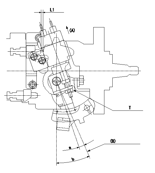
Adjustment of the accelerator switch
ON-OFF changeover point: e from the idle (shim thickness L2 mm)
Idle-c: ON
d ~ full: OFF
(B): Idle lever position
L1:Thickness of the shim L1 mm
----------
L2=3.3+-0.13mm c=5deg d=5deg e=5+-2deg
----------
L1=3.3(mm) T=5~7(Nm)(0.5~0.7(kgfm)) a=5+-2(deg) b=(25+-2(deg))
----------
L2=3.3+-0.13mm c=5deg d=5deg e=5+-2deg
----------
L1=3.3(mm) T=5~7(Nm)(0.5~0.7(kgfm)) a=5+-2(deg) b=(25+-2(deg))
Information:
Final Fuel Filter
The filter element collects and holds contaminants and cannot be washed or otherwise restored.To remove the used filter, proceed as follows:1. Stop the engine and close the diesel fuel line valve (if equipped).2. Unscrew and remove filter. 3. Clean the gasket sealing surfaces on the filter bases. 4. Lubricate the new filter gasket with clean diesel fuel.
Do not pour fuel into the new filter element before installing. Prime the system as instructed in the topic, PRIMING THE FUEL SYSTEM.
5. Tighten the filter by hand until the gasket contacts the base, then tighten 1/2 to 3/4 turn more.6. Start the engine and run at 1000 rpm for several minutes and check for leaks. If the engine fails to start, prime the fuel system. See the topic TO PRIME THE SYSTEM. Keep New Fuel Filters On Hand
Extra filters should be kept on hand for replacement. Always keep filters wrapped in their original carton to insure against dust and dirt accumulation which will shorten the life of the filters or may cause damage to the fuel injection equipment.To Prime The System
If air is trapped in the fuel system, the diesel engine will either not start, or will misfire. Then it is necessary to prime the system.The fuel priming pump is mounted on the fuel filter base. If the fuel filter is changed or if the engine has run out of fuel, prime the fuel system as follows: 1. Be sure the fuel line valve is open and the engine shutoff control is off.2. Unlock the fuel priming pump.3. Operate priming pump until increased resistance is felt.4. Lock fuel priming pump.If the engine fails to start or continues to misfire or smoke, further bleeding is necessary. With engine running, or with the use of the priming pump, loosen fuel line nuts, one at a time, several times in succession and allow fuel to run until free of air bubbles. Tighten fuel line nuts.
LOOSENING FUEL INJECTION LINE TO BLEED SYSTEMFuel Injection Equipment
When improper fuel injection is affecting engine operation, a systematic check should be made to determine the cause. The most likely cause is dirt or water in the fuel. Drain the sediment from the fuel tank. Check the fuel pressure gauge as mentioned in the topic, FUEL FILTERING SYSTEM. Replace the filters if necessary. Then prime the fuel system until clean fuel reaches the fuel injection pumps. If the fuel system is air bound, priming the system will overcome the difficulty.If the engine is running irregularly, smoking, or knocking, a fuel injection valve may not be spraying the fuel properly.Direct Injection System
The fuel system of direct injection engines is essentially the same as precombustion chamber engines. The absence of the precombustion chamber requires a different fuel nozzle and adapter. Externally the direct injection fuel nozzle resembles the precombustion chamber nozzle except it is longer in length. Nozzle testing and replacement procedure is the same as illustrated for the precombustion chamber engines, except that an extracting tool is used to remove
Have questions with 104760-4830?
Group cross 104760-4830 ZEXEL
Nissan
Nissan-Diesel
104760-4830
9 460 613 188
16700WJ012
INJECTION-PUMP ASSEMBLY
TD42
TD42