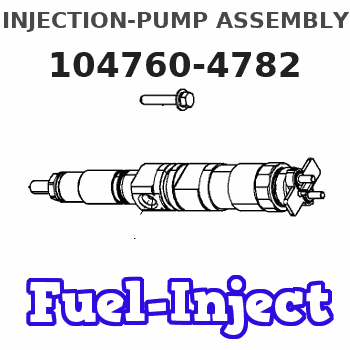
Information injection-pump assembly
BOSCH
F 01G 09W 00S
f01g09w00s
ZEXEL
104760-4782
1047604782
NISSAN-DIESEL
16700VB504
16700vb504
Rating:
Compare Prices: .
As an associate, we earn commssions on qualifying purchases through the links below

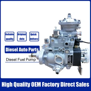
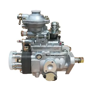
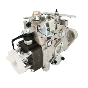
Diesel Pump Fuel Injection Pump Assembly, Compatible With ZEXEL, Compatible With NISSAN DIESEL TD42 104660-4781 NP-VE6/10F2000RNP181 16700-VB504
CHENUXO Diesel Pump Fuel Injection Pump Assembly , Compatible With ZEXEL , Compatible With NISSAN DIESEL TD42 104660-4781 NP-VE6/10F2000RNP181 16700-VB504 || Stable fuel supply: steadily extract fuel and deliver it at a certain pressure and flow rate to ensure the normal operation of the engine. || Pressure regulation: Equipped with a pressure regulator, it can automatically adjust the fuel pressure according to changes in working conditions. || Optimization design: The installation site adopts soundproof and shock-absorbing materials, further reducing the propagation of noise. || Monitoring feedback: Real time monitoring of fuel pressure, temperature, liquid level and other parameters, and feedback to the ECU.
CHENUXO Diesel Pump Fuel Injection Pump Assembly , Compatible With ZEXEL , Compatible With NISSAN DIESEL TD42 104660-4781 NP-VE6/10F2000RNP181 16700-VB504 || Stable fuel supply: steadily extract fuel and deliver it at a certain pressure and flow rate to ensure the normal operation of the engine. || Pressure regulation: Equipped with a pressure regulator, it can automatically adjust the fuel pressure according to changes in working conditions. || Optimization design: The installation site adopts soundproof and shock-absorbing materials, further reducing the propagation of noise. || Monitoring feedback: Real time monitoring of fuel pressure, temperature, liquid level and other parameters, and feedback to the ECU.

Diesel VE Pump Fuel Injection Pump Assembly 104660-4781 NP-VE6/10F2000RNP181 16700-VB504 Compatible For ZEXEL NISSAN DIESEL TD42
CFNCFJGJ [Part number] : 104660-4781 NP-VE6/10F2000RNP181 16700-VB504 || [Easy installation] : Standard interface, easy installation, plug and play, no professional skills, easy installation. || [Durable and reliable] : After multiple tests, long life, excellent quality, and stable work in extreme environments. || [Efficient and stable] : With the support of advanced technology, fuel supply is efficient and stable, ensuring the smooth flow of vehicles. || [High quality] : The use of high-quality materials and smart design, strict testing and verification, to ensure long-term stability and high reliability.
CFNCFJGJ [Part number] : 104660-4781 NP-VE6/10F2000RNP181 16700-VB504 || [Easy installation] : Standard interface, easy installation, plug and play, no professional skills, easy installation. || [Durable and reliable] : After multiple tests, long life, excellent quality, and stable work in extreme environments. || [Efficient and stable] : With the support of advanced technology, fuel supply is efficient and stable, ensuring the smooth flow of vehicles. || [High quality] : The use of high-quality materials and smart design, strict testing and verification, to ensure long-term stability and high reliability.

WBFRYEE Diesel Fuel Injection Pump 104660-4781 104760-4781 NP-VE6/10F2000RNP181 16700VB504 Compatible with Nissan
WBFRYEE Firm structure and stable || Reliability, firmness and durability || Ensure the stable operation of the engine. || Provide a stable fuel supply to ensure the normal operation of the vehicle. || Fuel pump metering unit is an important part of engine electronic gasoline injection system.
WBFRYEE Firm structure and stable || Reliability, firmness and durability || Ensure the stable operation of the engine. || Provide a stable fuel supply to ensure the normal operation of the vehicle. || Fuel pump metering unit is an important part of engine electronic gasoline injection system.
You can express buy:
USD 419.1
19-05-2025
19-05-2025
Diesel Fuel Injection Pump 104660-4781 104760-4781 NP-VE6/10F2000RNP181 16700VB504 For NISSAN
USD 393.14
13-05-2025
13-05-2025
Diesel Fuel Injection Pump 104660-4781 104760-4781 NP-VE6/10F2000RNP181 16700VB504 For NISSAN
USD 406.7
28-04-2025
28-04-2025
Diesel VE Pump Fuel Injection Pump Assembly 104660-4781 NP-VE6/10F2000RNP181 16700-VB504 For ZEXEL NISSAN DIESEL TD42
Images:
USD 395.08

[31-May-2025]
USD 423.22

[31-May-2025]
USD 411

[28-Apr-2025]
USD 436.28

[30-May-2025]
Cross reference number
BOSCH
F 01G 09W 00S
f01g09w00s
ZEXEL
104760-4782
1047604782
NISSAN-DIESEL
16700VB504
16700vb504
Zexel num
Bosch num
Firm num
Name
104760-4782
F 01G 09W 00S
16700VB504 NISSAN-DIESEL
INJECTION-PUMP ASSEMBLY
TD42 * K
TD42 * K
Calibration Data:
Adjustment conditions
Test oil
1404 Test oil ISO4113orSAEJ967d
1404 Test oil ISO4113orSAEJ967d
Test oil temperature
degC
45
45
50
Nozzle
105780-0060
Bosch type code
NP-DN0SD1510
Nozzle holder
105780-2150
Opening pressure
MPa
13
13
13.3
Opening pressure
kgf/cm2
133
133
136
Injection pipe
157805-7320
Injection pipe
Inside diameter - outside diameter - length (mm) mm 2-6-450
Inside diameter - outside diameter - length (mm) mm 2-6-450
Joint assembly
157641-4720
Tube assembly
157641-4020
Transfer pump pressure
kPa
20
20
20
Transfer pump pressure
kgf/cm2
0.2
0.2
0.2
Direction of rotation (viewed from drive side)
Right R
Right R
Injection timing adjustment
Pump speed
r/min
1000
1000
1000
Average injection quantity
mm3/st.
45.3
44.8
45.8
Difference in delivery
mm3/st.
3.5
Basic
*
Oil temperature
degC
50
48
52
Injection timing adjustment_02
Pump speed
r/min
600
600
600
Average injection quantity
mm3/st.
43.8
41.3
46.3
Oil temperature
degC
50
48
52
Injection timing adjustment_03
Pump speed
r/min
1000
1000
1000
Average injection quantity
mm3/st.
45.3
44.3
46.3
Difference in delivery
mm3/st.
4
Basic
*
Oil temperature
degC
50
48
52
Injection timing adjustment_04
Pump speed
r/min
2000
2000
2000
Average injection quantity
mm3/st.
43.3
40.8
45.8
Oil temperature
degC
50
48
52
Injection quantity adjustment
Pump speed
r/min
2300
2300
2300
Average injection quantity
mm3/st.
17.8
15.8
19.8
Difference in delivery
mm3/st.
5
Basic
*
Oil temperature
degC
52
50
54
Injection quantity adjustment_02
Pump speed
r/min
2100
2100
2100
Average injection quantity
mm3/st.
43.1
38.6
47.6
Oil temperature
degC
52
50
54
Injection quantity adjustment_03
Pump speed
r/min
2300
2300
2300
Average injection quantity
mm3/st.
17.8
15.3
20.3
Basic
*
Oil temperature
degC
52
50
54
Injection quantity adjustment_04
Pump speed
r/min
2500
2500
2500
Average injection quantity
mm3/st.
5
Oil temperature
degC
55
52
58
Governor adjustment
Pump speed
r/min
350
350
350
Average injection quantity
mm3/st.
10.1
8.1
12.1
Difference in delivery
mm3/st.
2
Basic
*
Oil temperature
degC
48
46
50
Governor adjustment_02
Pump speed
r/min
350
350
350
Average injection quantity
mm3/st.
10.1
7.6
12.6
Difference in delivery
mm3/st.
2.5
Basic
*
Oil temperature
degC
48
46
50
Timer adjustment
Pump speed
r/min
100
100
100
Average injection quantity
mm3/st.
60
50
80
Basic
*
Oil temperature
degC
48
46
50
Remarks
Full
Full
Timer adjustment_02
Pump speed
r/min
100
100
100
Average injection quantity
mm3/st.
60
50
80
Oil temperature
degC
48
46
50
Remarks
Full
Full
Speed control lever angle
Pump speed
r/min
250
250
250
Average injection quantity
mm3/st.
5
Oil temperature
degC
48
46
50
Remarks
Magnet OFF at full-load position
Magnet OFF at full-load position
Speed control lever angle_02
Pump speed
r/min
350
350
350
Average injection quantity
mm3/st.
0
0
0
Oil temperature
degC
48
46
50
Remarks
Magnet OFF at idling position
Magnet OFF at idling position
0000000901
Pump speed
r/min
1000
1000
1000
Overflow quantity
cm3/min
400
270
530
Oil temperature
degC
50
48
52
Stop lever angle
Pump speed
r/min
1000
1000
1000
Pressure
kPa
422
402
442
Pressure
kgf/cm2
4.3
4.1
4.5
Basic
*
Oil temperature
degC
50
48
52
Stop lever angle_02
Pump speed
r/min
1000
1000
1000
Pressure
kPa
422
393
451
Pressure
kgf/cm2
4.3
4
4.6
Basic
*
Oil temperature
degC
50
48
52
Stop lever angle_03
Pump speed
r/min
1800
1800
1800
Pressure
kPa
686
647
725
Pressure
kgf/cm2
7
6.6
7.4
Oil temperature
degC
50
48
52
0000001101
Pump speed
r/min
1000
1000
1000
Timer stroke
mm
2.9
2.7
3.1
Basic
*
Oil temperature
degC
50
48
52
_02
Pump speed
r/min
650
650
650
Timer stroke
mm
1.2
0.7
1.7
Oil temperature
degC
50
48
52
_03
Pump speed
r/min
1000
1000
1000
Timer stroke
mm
2.9
2.6
3.2
Basic
*
Oil temperature
degC
50
48
52
_04
Pump speed
r/min
1800
1800
1800
Timer stroke
mm
6.6
6.1
7.1
Oil temperature
degC
50
48
52
_05
Pump speed
r/min
2200
2200
2200
Timer stroke
mm
8.2
7.7
8.6
Oil temperature
degC
52
50
54
0000001201
Max. applied voltage
V
8
8
8
Test voltage
V
13
12
14
0000001501
Pump speed
r/min
1000
1000
1000
Height
m
2000
2000
2000
Atmospheric pressure difference
kPa
-21.9
-23.2
-20.6
Atmospheric pressure difference
mmHg
-164
-174
-154
Average injection quantity
mm3/st.
36.8
35.3
38.3
Decrease qty
mm3/st.
8.5
8.5
8.5
Decrease rate
%
18.8
18.8
18.8
Basic
*
Oil temperature
degC
50
48
52
_02
Pump speed
r/min
1000
1000
1000
Height
m
0
0
0
Atmospheric pressure difference
kPa
0
0
0
Atmospheric pressure difference
mmHg
0
0
0
Average injection quantity
mm3/st.
45.3
44.3
46.3
Oil temperature
degC
50
48
52
_03
Pump speed
r/min
1000
1000
1000
Height
m
500
500
500
Atmospheric pressure difference
kPa
-5.9
-9.2
-2.6
Atmospheric pressure difference
mmHg
-44
-69
-19
Average injection quantity
mm3/st.
45.3
45.3
45.3
Oil temperature
degC
50
48
52
_04
Pump speed
r/min
1000
1000
1000
Height
m
2000
2000
2000
Atmospheric pressure difference
kPa
-21.9
-23.2
-20.6
Atmospheric pressure difference
mmHg
-164
-174
-154
Average injection quantity
mm3/st.
36.8
34.8
38.8
Basic
*
Oil temperature
degC
50
48
52
_05
Pump speed
r/min
1000
1000
1000
Height
m
4000
4000
4000
Atmospheric pressure difference
kPa
-39.7
-41
-38.4
Atmospheric pressure difference
mmHg
-298
-308
-288
Average injection quantity
mm3/st.
29.8
29.8
29.8
Oil temperature
degC
50
48
52
Timing setting
K dimension
mm
3.3
3.2
3.4
KF dimension
mm
6.64
6.54
6.74
MS dimension
mm
1
0.9
1.1
Control lever angle alpha
deg.
55.5
51.5
59.5
Control lever angle beta
deg.
40
35
45
Information:
Altitude Operation
The fuel system settings and altitude limits are stamped on the engine information plate. When an engine is moved to a higher altitude, these settings must be changed by your Caterpillar dealer in order to prevent damaging the turbocharger, and to provide maximum engine efficiency. If the engine is moved to a lower altitude than that which is stamped on the engine information plate, the engine can be operated safely; however, it will deliver less than rated horsepower, and the fuel settings should be changed by your Caterpillar dealer to obtain rated horsepower.Stopping
1. Flywheel clutch operation: Quickly pull the clutch lever to the released position. For electric set operation, see the GENERATOR SET OPERATION instructions. For Woodward Governor operation, see the topic, WOODWARD GOVERNORS, Stopping the Engine. 2. Reduce engine speed to half speed. Run for 5 minutes to cool engine.3. Reduce engine speed to low idle.4. Observe the crankcase oil level while the engine is idling. Maintain the oil level between the ADD and FULL marks on the side of the dipstick stamped, CHECK WITH ENGINE RUNNING. See the LUBRICATION AND MAINTENANCE SECTION.5. Stop the engine. After Stopping Checks And Procedures
1. Fill the fuel tank. See the LUBRICATION AND MAINTENANCE SECTION: Fuel Tank Maintenance.2. Drain the raw water system if below freezing temperatures are expected; see: Draining Raw Water System.3. If below freezing temperatures are expected, allow the engine jacket water expansion tank to cool; then check the coolant for proper antifreeze protection. Add permanent-type antifreeze, if required.4. Repair any leaks, make major adjustments, tighten loose bolts, etc.5. Observe the Service Meter reading. Perform the periodic maintenance as instructed in the LUBRICATION AND MAINTENANCE CHART.
SERVICE METER
Have questions with 104760-4782?
Group cross 104760-4782 ZEXEL
Nissan
Nissan-Diesel
Nissan
Nissan-Diesel
Nissan
Nissan-Diesel
Nissan
Nissan-Diesel
Nissan
Nissan-Diesel
Nissan
Nissan-Diesel
104760-4782
F 01G 09W 00S
16700VB504
INJECTION-PUMP ASSEMBLY
TD42
TD42