Information injection-pump assembly
ZEXEL
104760-4610
1047604610
NISSAN
167001Y102
167001y102
Rating:
Cross reference number
ZEXEL
104760-4610
1047604610
NISSAN
167001Y102
167001y102
Zexel num
Bosch num
Firm num
Name
Calibration Data:
Adjustment conditions
Test oil
1404 Test oil ISO4113orSAEJ967d
1404 Test oil ISO4113orSAEJ967d
Test oil temperature
degC
45
45
50
Nozzle
105000-2010
Bosch type code
NP-DN12SD12TT
Nozzle holder
105780-2080
Opening pressure
MPa
14.7
14.7
15.19
Opening pressure
kgf/cm2
150
150
155
Injection pipe
Inside diameter - outside diameter - length (mm) mm 2-6-840
Inside diameter - outside diameter - length (mm) mm 2-6-840
Transfer pump pressure
kPa
20
20
20
Transfer pump pressure
kgf/cm2
0.2
0.2
0.2
Direction of rotation (viewed from drive side)
Right R
Right R
Injection timing adjustment
Pump speed
r/min
1000
1000
1000
Average injection quantity
mm3/st.
45.5
45
46
Difference in delivery
mm3/st.
3.5
Basic
*
Oil temperature
degC
50
48
52
Injection timing adjustment_02
Pump speed
r/min
600
600
600
Average injection quantity
mm3/st.
45.1
45.1
45.1
Oil temperature
degC
50
48
52
Injection timing adjustment_03
Pump speed
r/min
1000
1000
1000
Average injection quantity
mm3/st.
45.5
44.5
46.5
Difference in delivery
mm3/st.
4
Basic
*
Oil temperature
degC
50
48
52
Injection timing adjustment_04
Pump speed
r/min
2000
2000
2000
Average injection quantity
mm3/st.
38.7
38.7
38.7
Oil temperature
degC
50
48
52
Injection quantity adjustment
Pump speed
r/min
2300
2300
2300
Average injection quantity
mm3/st.
16.6
14.6
18.6
Difference in delivery
mm3/st.
5
Basic
*
Oil temperature
degC
52
50
54
Injection quantity adjustment_02
Pump speed
r/min
2500
2500
2500
Average injection quantity
mm3/st.
5
Oil temperature
degC
55
52
58
Injection quantity adjustment_03
Pump speed
r/min
2100
2100
2100
Average injection quantity
mm3/st.
36.3
36.3
36.3
Oil temperature
degC
52
50
54
Injection quantity adjustment_04
Pump speed
r/min
2300
2300
2300
Average injection quantity
mm3/st.
16.6
14.1
19.1
Basic
*
Oil temperature
degC
52
50
54
Governor adjustment
Pump speed
r/min
350
350
350
Average injection quantity
mm3/st.
8.8
6.8
10.8
Difference in delivery
mm3/st.
2
Basic
*
Oil temperature
degC
48
46
50
Governor adjustment_02
Pump speed
r/min
350
350
350
Average injection quantity
mm3/st.
8.8
6.3
11.3
Difference in delivery
mm3/st.
2.5
Basic
*
Oil temperature
degC
48
46
50
Timer adjustment
Pump speed
r/min
300
300
300
Average injection quantity
mm3/st.
55
53
57
Basic
*
Oil temperature
degC
48
46
50
Remarks
Adjust full speed position using stop lever.
Adjust full speed position using stop lever.
Timer adjustment_02
Pump speed
r/min
300
300
300
Average injection quantity
mm3/st.
55
52.5
57.5
Oil temperature
degC
48
46
50
Remarks
Full
Full
Speed control lever angle
Pump speed
r/min
350
350
350
Average injection quantity
mm3/st.
0
0
0
Oil temperature
degC
48
46
50
Remarks
Magnet OFF at idling position
Magnet OFF at idling position
0000000901
Pump speed
r/min
1000
1000
1000
Overflow quantity
cm3/min
400
270
530
Oil temperature
degC
50
48
52
Stop lever angle
Pump speed
r/min
1000
1000
1000
Pressure
kPa
324
304
344
Pressure
kgf/cm2
3.3
3.1
3.5
Basic
*
Oil temperature
degC
50
48
52
Stop lever angle_02
Pump speed
r/min
1000
1000
1000
Pressure
kPa
324
295
353
Pressure
kgf/cm2
3.3
3
3.6
Basic
*
Oil temperature
degC
50
48
52
Stop lever angle_03
Pump speed
r/min
1800
1800
1800
Pressure
kPa
608
569
647
Pressure
kgf/cm2
6.2
5.8
6.6
Oil temperature
degC
50
48
52
0000001101
Pump speed
r/min
1000
1000
1000
Timer stroke
mm
1.6
1.4
1.8
Basic
*
Oil temperature
degC
50
48
52
_02
Pump speed
r/min
800
800
800
Timer stroke
mm
0.5
0
1
Oil temperature
degC
50
48
52
_03
Pump speed
r/min
1000
1000
1000
Timer stroke
mm
1.6
1.3
1.9
Basic
*
Oil temperature
degC
50
48
52
_04
Pump speed
r/min
1800
1800
1800
Timer stroke
mm
5.8
5.3
6.3
Oil temperature
degC
50
48
52
_05
Pump speed
r/min
2200
2200
2200
Timer stroke
mm
7.4
6.9
7.8
Oil temperature
degC
52
50
54
0000001201
Max. applied voltage
V
8
8
8
Test voltage
V
13
12
14
Timing setting
K dimension
mm
3.3
3.2
3.4
KF dimension
mm
6.64
6.54
6.74
MS dimension
mm
1
0.9
1.1
Control lever angle alpha
deg.
25
23
27
Control lever angle beta
deg.
40
35
45
Test data Ex:
0000001801 STOP LEVER ADJUSTMENT
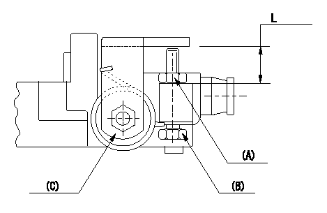
Adjustment of the stop lever
Adjust adjusting bolt (B) so that the starting injection quantity is within the standard.
Fix using nut.
(A) Adjusting nut
(C) Starting injection quantity adjusting lever
----------
----------
L=15.0~18.5mm
----------
----------
L=15.0~18.5mm
Information:
1. Remove tube and elbow (1).2. Remove tube and oil sump (2).
Turn the crankshaft so the piston is down, and remove the ridge of carbon with emery cloth from each liner before removing the pistons. Damage can be caused to the pistons during removal by the build up of carbon if it is not removed.
3. Turn the crankshaft until the connecting rod cap to be removed is at bottom center.4. Remove connecting rod cap (3) from the connecting rod.
Put identification marks on the connecting rod caps as to their location in the engine. Keep the caps with their respective piston.
5. Push the connecting rod and piston away from the crankshaft until the piston rings are above the cylinder liner. Remove piston (4) and the connecting rod from the engine.
Use tape to hold the bearing halves together and to identify the number of the cylinder.
Install Pistons
1. Turn the crankshaft until the bearing journal for the piston to be installed is at bottom center.2. Put clean engine oil on the crankshaft journal and on the inside of the cylinder liner.3. Put clean engine oil on the piston rings and connecting rod bearings.4. Move the piston ring gaps 180° apart.5. Use tool (A), and put the piston and connecting rod in its original location in the cylinder block. Be sure the numbered side of the connecting rod is toward the right side of the engine. This is when viewed from the front of the engine.
Be sure the connecting rod bolts do not contact the crankshaft journal during installation of the piston.
6. Use a hammer handle, and lightly tap the piston into position.
When the connecting rod caps are installed, make sure the number on the side of the cap is next to the same number on the connecting rod. The numbers must be away from the camshaft.
7. Install connecting rod cap (1) and the nuts which hold it. Tighten the nuts to a torque value of: Cadmium plated nuts (silver color) - 100 N m (75 lb.ft).Phosphated nuts (dull black color) - 130 N m (95 lb.ft.).8. Follow the same procedure for installation of the remainder of the pistons. 9. Install tube and elbow (2). Install tube and oil sump (3).End By:a. install oil panb. install cylinder head assemblyDisassemble Pistons
Start By:a. remove pistons Put identification marks on all parts for correct assembly.1. Remove rings (1) from piston (2) with tool (A). 2. Remove retaining ring (3) from each side of the piston with tool (B).3. Remove pin (4) and connecting rod (5) from piston (2). 4. Remove bolts (7) from the connecting rod.5. Remove bushing (6) from connecting rod (5) with tool group (C).6. Check all of the parts of the piston and rod for damage and wear. See Specification for minimum and maximum wear dimensions.Assemble Pistons
1. Install bolts (1) in connecting rod (2).2. Install the bushing in connecting rod (2) with tool group (A) and a press. Hone the bushing to the correct size. See Specifications for the correct dimension. 3.