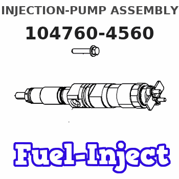
Information injection-pump assembly
ZEXEL
104760-4560
1047604560
NISSAN-DIESEL
167000Y713
167000y713
Rating:
Cross reference number
ZEXEL
104760-4560
1047604560
NISSAN-DIESEL
167000Y713
167000y713
Zexel num
Bosch num
Firm num
Name
Calibration Data:
Adjustment conditions
Test oil
1404 Test oil ISO4113orSAEJ967d
1404 Test oil ISO4113orSAEJ967d
Test oil temperature
degC
45
45
50
Nozzle
105000-2010
Bosch type code
NP-DN12SD12TT
Nozzle holder
105780-2080
Opening pressure
MPa
14.7
14.7
15.19
Opening pressure
kgf/cm2
150
150
155
Injection pipe
Inside diameter - outside diameter - length (mm) mm 2-6-840
Inside diameter - outside diameter - length (mm) mm 2-6-840
Transfer pump pressure
kPa
20
20
20
Transfer pump pressure
kgf/cm2
0.2
0.2
0.2
Direction of rotation (viewed from drive side)
Right R
Right R
(Solenoid timer adjustment condition)
OFF
Injection timing adjustment
Pump speed
r/min
1000
1000
1000
Average injection quantity
mm3/st.
48.9
48.4
49.4
Difference in delivery
mm3/st.
3.5
Basic
*
Oil temperature
degC
50
48
52
Injection timing adjustment_02
Pump speed
r/min
600
600
600
Average injection quantity
mm3/st.
49.1
47.1
51.1
Oil temperature
degC
50
48
52
Injection timing adjustment_03
Pump speed
r/min
1000
1000
1000
Average injection quantity
mm3/st.
48.9
47.9
49.9
Difference in delivery
mm3/st.
4
Basic
*
Oil temperature
degC
50
48
52
Injection timing adjustment_04
Pump speed
r/min
1300
1300
1300
Average injection quantity
mm3/st.
50
50
50
Oil temperature
degC
50
48
52
Injection timing adjustment_05
Pump speed
r/min
1600
1600
1600
Average injection quantity
mm3/st.
47.1
47.1
47.1
Oil temperature
degC
50
48
52
Injection timing adjustment_06
Pump speed
r/min
2000
2000
2000
Average injection quantity
mm3/st.
42.1
40
44.2
Oil temperature
degC
50
48
52
Injection quantity adjustment
Pump speed
r/min
2300
2300
2300
Average injection quantity
mm3/st.
16.6
14.6
18.6
Difference in delivery
mm3/st.
5
Basic
*
Oil temperature
degC
52
50
54
Injection quantity adjustment_02
Pump speed
r/min
2500
2500
2500
Average injection quantity
mm3/st.
5
Oil temperature
degC
55
52
58
Injection quantity adjustment_03
Pump speed
r/min
2100
2100
2100
Average injection quantity
mm3/st.
40
35.5
44.5
Oil temperature
degC
52
50
54
Injection quantity adjustment_04
Pump speed
r/min
2300
2300
2300
Average injection quantity
mm3/st.
16.6
14.1
19.1
Basic
*
Oil temperature
degC
52
50
54
Governor adjustment
Pump speed
r/min
350
350
350
Average injection quantity
mm3/st.
8.8
6.8
10.8
Difference in delivery
mm3/st.
2
Basic
*
Oil temperature
degC
48
46
50
Governor adjustment_02
Pump speed
r/min
350
350
350
Average injection quantity
mm3/st.
8.8
6.3
11.3
Difference in delivery
mm3/st.
2.5
Basic
*
Oil temperature
degC
48
46
50
Timer adjustment
Pump speed
r/min
100
100
100
Average injection quantity
mm3/st.
60
50
80
Basic
*
Oil temperature
degC
48
46
50
Remarks
Full
Full
Timer adjustment_02
Pump speed
r/min
100
100
100
Average injection quantity
mm3/st.
60
50
80
Oil temperature
degC
48
46
50
Remarks
Full
Full
Speed control lever angle
Pump speed
r/min
350
350
350
Average injection quantity
mm3/st.
0
0
0
Oil temperature
degC
48
46
50
Remarks
Magnet OFF at idling position
Magnet OFF at idling position
Speed control lever angle_02
Pump speed
r/min
250
250
250
Average injection quantity
mm3/st.
5
Oil temperature
degC
48
46
50
Remarks
Magnet OFF at full-load position
Magnet OFF at full-load position
0000000901
Pump speed
r/min
1000
1000
1000
Overflow quantity with S/T ON
cm3/min
400
270
530
Oil temperature
degC
50
48
52
_02
Pump speed
r/min
1000
1000
1000
Overflow quantity with S/T ON
cm3/min
450
320
580
Oil temperature
degC
50
48
52
Remarks
Without an O-ring
Without an O-ring
Stop lever angle
Pump speed
r/min
1000
1000
1000
Pressure with S/T ON
kPa
500
461
539
Pressure with S/T ON
kgf/cm2
5.1
4.7
5.5
Pressure with S/T OFF
kPa
324
304
344
Pressure with S/T OFF
kgf/cm2
3.3
3.1
3.5
Basic
*
Oil temperature
degC
50
48
52
Stop lever angle_02
Pump speed
r/min
1000
1000
1000
Pressure
kPa
324
295
353
Pressure
kgf/cm2
3.3
3
3.6
Basic
*
Oil temperature
degC
50
48
52
Stop lever angle_03
Pump speed
r/min
1800
1800
1800
Pressure
kPa
569
530
608
Pressure
kgf/cm2
5.8
5.4
6.2
Oil temperature
degC
50
48
52
0000001101
Pump speed
r/min
1000
1000
1000
Timer stroke with S/T ON
mm
3.8
3.4
4.2
Timer stroke with S/T OFF
mm
1.6
1.4
1.8
Basic
*
Oil temperature
degC
50
48
52
_02
Pump speed
r/min
800
800
800
Timer stroke with S/T OFF
mm
0.5
0
1
Oil temperature
degC
50
48
52
_03
Pump speed
r/min
1000
1000
1000
Timer stroke with S/T ON
mm
3.8
3.3
4.3
Timer stroke with S/T OFF
mm
1.6
1.3
1.9
Basic
*
Oil temperature
degC
50
48
52
_04
Pump speed
r/min
1800
1800
1800
Timer stroke with S/T OFF
mm
5.5
5
6
Oil temperature
degC
50
48
52
_05
Pump speed
r/min
2200
2200
2200
Timer stroke with S/T OFF
mm
7.4
6.9
7.8
Oil temperature
degC
52
50
54
0000001201
Max. applied voltage
V
8
8
8
Test voltage
V
13
12
14
0000001401
Pump speed
r/min
1200
1200
1200
Average injection quantity
mm3/st.
22
21.5
22.5
Timer stroke TA
mm
2.5
2.3
2.7
Timer stroke variation dT
mm
0.1
0.1
0.1
Basic
*
Oil temperature
degC
50
48
52
_02
Pump speed
r/min
1200
1200
1200
Average injection quantity
mm3/st.
22
21
23
Timer stroke TA
mm
2.5
2.2
2.8
Basic
*
Oil temperature
degC
50
48
52
_03
Pump speed
r/min
1200
1200
1200
Average injection quantity
mm3/st.
15
12.5
17.5
Timer stroke TA
mm
2.1
1.4
2.8
Oil temperature
degC
50
48
52
Timing setting
K dimension
mm
3.3
3.2
3.4
KF dimension
mm
6.64
6.54
6.74
MS dimension
mm
1
0.9
1.1
Control lever angle alpha
deg.
25
23
27
Control lever angle beta
deg.
40
35
45
Test data Ex:
0000001801 POTENTIOMETER ADJUSTMENT
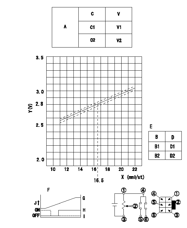
Adjustment of the potentiometer
At pump speed N1 and a control lever position a from idle (gap L1), measure the injection quantity and convert it to a voltage value. Then adjust the potentiometer.
Voltage conversion formula: V+-0.03 = 0.044Q+2.07
A:Potentiometer performance standards
C:Position of the control lever
C1:Idle
C2:Full speed
V:Potentiometer voltage
E:Standards for the potentiometer's ON - OFF switch
B:Conversion point
B1:OFF-->ON
B2:OFF-->ON
D:Lever opening (from idle)
Vi:Applied voltage
F:Connecting diagram for the potentiometer
G:Output when (2) and (3) connected.
H:When (4) or (6) connected: switch OFF to ON.
I:When (4) or (5) connected: switch ON to OFF.
J:Output
----------
N1=700r/min a=7.5deg L1=4.9mm Vi=10V
----------
V1=1.6+-0.4V V2=8.0+-0.55V D1=6.0+-3.5deg D2=19.5+-3.5deg Vi=10V
----------
N1=700r/min a=7.5deg L1=4.9mm Vi=10V
----------
V1=1.6+-0.4V V2=8.0+-0.55V D1=6.0+-3.5deg D2=19.5+-3.5deg Vi=10V
Information:
Start By:a. remove radiatorb. remove hydraulic pumpc. remove crankshaft pulleyd. remove alternatore. remove intake manifoldf. remove starting motorg. remove oil filterh. remove transmission
All wires, hoses, lines and linkage that is disconnected must be tied or wired out of the way to prevent damage when removing engine.
1. Identify and disconnect all electrical connections to the engine. Disconnect hydraulic lines and cab heater hoses. Disconnect all fuel lines and throttle controls. Tie or wire all wires, hoses, lines and linkage out of the way for engine removal.2. Remove front and rear engine mount bolts (1). 3. With the forks of a lift truck positioned together, position forks centered over the engine as illustrated. Install tooling (A) and then run a chain through the existing engine lifting eyes and tooling (A) as illustrated. Raise engine up slightly and start to remove engine. 4. With the engine part of the way out, remove four bolts (2) and remove rear mount bracket (3). Repeat step for the other rear mount bracket. With both rear mount brackets removed, finish removing engine. Weight of the engine is 340 Kg (750 lbs.). At the time of installation, tighten front mount bolts to a torque of 370 50 N m (270 37 lb.ft.) and rear mount bolts to a torque of 100 15 N m (75 11 lb.ft.). Install in the reverse order.End By:a. install transmissionb. install oil filterc. install starting motord. install intake manifolde. install alternatorf. install crankshaft pulleyg. install hydraulic pumph. install radiator