Information injection-pump assembly
ZEXEL
104760-4470
1047604470
NISSAN-DIESEL
1670051N14
1670051n14
Rating:
Cross reference number
ZEXEL
104760-4470
1047604470
NISSAN-DIESEL
1670051N14
1670051n14
Zexel num
Bosch num
Firm num
Name
Calibration Data:
Adjustment conditions
Test oil
1404 Test oil ISO4113orSAEJ967d
1404 Test oil ISO4113orSAEJ967d
Test oil temperature
degC
45
45
50
Nozzle
105780-0060
Bosch type code
NP-DN0SD1510
Nozzle holder
105780-2150
Opening pressure
MPa
13
13
13.3
Opening pressure
kgf/cm2
133
133
136
Injection pipe
157805-7320
Injection pipe
Inside diameter - outside diameter - length (mm) mm 2-6-450
Inside diameter - outside diameter - length (mm) mm 2-6-450
Joint assembly
157641-4720
Tube assembly
157641-4020
Transfer pump pressure
kPa
20
20
20
Transfer pump pressure
kgf/cm2
0.2
0.2
0.2
Direction of rotation (viewed from drive side)
Right R
Right R
(Solenoid timer adjustment condition)
With S/T O-ring; S/T OFF. OFF
With S/T O-ring; S/T OFF. OFF
Injection timing adjustment
Pump speed
r/min
500
500
500
Boost pressure
kPa
0
0
0
Boost pressure
mmHg
0
0
0
Average injection quantity
mm3/st.
46.3
45.8
46.8
Basic
*
Oil temperature
degC
48
46
50
Remarks
NA
NA
Injection timing adjustment_02
Pump speed
r/min
700
700
700
Boost pressure
kPa
16
14.7
17.3
Boost pressure
mmHg
120
110
130
Average injection quantity
mm3/st.
53.7
53.2
54.2
Basic
*
Oil temperature
degC
50
48
52
Remarks
CBS
CBS
Injection timing adjustment_03
Pump speed
r/min
1000
1000
1000
Boost pressure
kPa
53.3
52
54.6
Boost pressure
mmHg
400
390
410
Average injection quantity
mm3/st.
58.3
57.8
58.8
Difference in delivery
mm3/st.
4
Basic
*
Oil temperature
degC
50
48
52
Injection timing adjustment_04
Pump speed
r/min
500
500
500
Boost pressure
kPa
0
0
0
Boost pressure
mmHg
0
0
0
Average injection quantity
mm3/st.
46.3
45.3
47.3
Basic
*
Oil temperature
degC
48
46
50
Injection timing adjustment_05
Pump speed
r/min
700
700
700
Boost pressure
kPa
16
14.7
17.3
Boost pressure
mmHg
120
110
130
Average injection quantity
mm3/st.
53.7
52.7
54.7
Basic
*
Oil temperature
degC
50
48
52
Remarks
CBS
CBS
Injection timing adjustment_06
Pump speed
r/min
1000
1000
1000
Boost pressure
kPa
0
0
0
Boost pressure
mmHg
0
0
0
Average injection quantity
mm3/st.
51.1
48.6
53.6
Oil temperature
degC
50
48
52
Injection timing adjustment_07
Pump speed
r/min
1000
1000
1000
Boost pressure
kPa
53.3
52
54.6
Boost pressure
mmHg
400
390
410
Average injection quantity
mm3/st.
58.3
57.3
59.3
Difference in delivery
mm3/st.
4.5
Basic
*
Oil temperature
degC
50
48
52
Injection timing adjustment_08
Pump speed
r/min
2000
2000
2000
Boost pressure
kPa
53.3
52
54.6
Boost pressure
mmHg
400
390
410
Average injection quantity
mm3/st.
61.1
58.6
63.6
Oil temperature
degC
50
48
52
Injection quantity adjustment
Pump speed
r/min
2300
2300
2300
Boost pressure
kPa
53.3
52
54.6
Boost pressure
mmHg
400
390
410
Average injection quantity
mm3/st.
18.3
16.3
20.3
Basic
*
Oil temperature
degC
52
50
54
Injection quantity adjustment_02
Pump speed
r/min
2500
2500
2500
Boost pressure
kPa
53.3
52
54.6
Boost pressure
mmHg
400
390
410
Average injection quantity
mm3/st.
5
Oil temperature
degC
55
52
58
Injection quantity adjustment_03
Pump speed
r/min
2100
2100
2100
Boost pressure
kPa
53.3
52
54.6
Boost pressure
mmHg
400
390
410
Average injection quantity
mm3/st.
55.2
50.7
59.7
Oil temperature
degC
52
50
54
Injection quantity adjustment_04
Pump speed
r/min
2300
2300
2300
Boost pressure
kPa
53.3
52
54.6
Boost pressure
mmHg
400
390
410
Average injection quantity
mm3/st.
18.3
15.8
20.8
Basic
*
Oil temperature
degC
52
50
54
Governor adjustment
Pump speed
r/min
350
350
350
Boost pressure
kPa
0
0
0
Boost pressure
mmHg
0
0
0
Average injection quantity
mm3/st.
12.5
10.5
14.5
Difference in delivery
mm3/st.
2
Basic
*
Oil temperature
degC
48
46
50
Governor adjustment_02
Pump speed
r/min
350
350
350
Boost pressure
kPa
0
0
0
Boost pressure
mmHg
0
0
0
Average injection quantity
mm3/st.
12.5
10
15
Difference in delivery
mm3/st.
2.5
Basic
*
Oil temperature
degC
48
46
50
Timer adjustment
Pump speed
r/min
100
100
100
Boost pressure
kPa
0
0
0
Boost pressure
mmHg
0
0
0
Average injection quantity
mm3/st.
58
48
78
Basic
*
Oil temperature
degC
48
46
50
Remarks
Full
Full
Timer adjustment_02
Pump speed
r/min
100
100
100
Boost pressure
kPa
0
0
0
Boost pressure
mmHg
0
0
0
Average injection quantity
mm3/st.
58
48
78
Oil temperature
degC
48
46
50
Remarks
Full
Full
Speed control lever angle
Pump speed
r/min
350
350
350
Boost pressure
kPa
0
0
0
Boost pressure
mmHg
0
0
0
Average injection quantity
mm3/st.
0
0
0
Oil temperature
degC
48
46
50
Remarks
Magnet OFF at idling position
Magnet OFF at idling position
0000000901
Pump speed
r/min
1000
1000
1000
Boost pressure
kPa
53.3
52
54.6
Boost pressure
mmHg
400
390
410
Overflow quantity with S/T ON
cm3/min
420
290
550
Oil temperature
degC
50
48
52
Remarks
With an O-ring
With an O-ring
_02
Pump speed
r/min
1000
1000
1000
Boost pressure
kPa
53.3
52
54.6
Boost pressure
mmHg
400
390
410
Overflow quantity with S/T ON
cm3/min
470
340
600
Oil temperature
degC
50
48
52
Remarks
Without an O-ring
Without an O-ring
Stop lever angle
Pump speed
r/min
1000
1000
1000
Boost pressure
kPa
53.3
52
54.6
Boost pressure
mmHg
400
390
410
Pressure with S/T ON
kPa
431
392
470
Pressure with S/T ON
kgf/cm2
4.4
4
4.8
Pressure with S/T OFF
kPa
333
304
362
Pressure with S/T OFF
kgf/cm2
3.4
3.1
3.7
Basic
*
Oil temperature
degC
50
48
52
Stop lever angle_02
Pump speed
r/min
1000
1000
1000
Boost pressure
kPa
53.3
52
54.6
Boost pressure
mmHg
400
390
410
Pressure with S/T OFF
kPa
333
294
372
Pressure with S/T OFF
kgf/cm2
3.4
3
3.8
Basic
*
Oil temperature
degC
50
48
52
Stop lever angle_03
Pump speed
r/min
1700
1700
1700
Boost pressure
kPa
53.3
52
54.6
Boost pressure
mmHg
400
390
410
Pressure with S/T OFF
kPa
549
510
588
Pressure with S/T OFF
kgf/cm2
5.6
5.2
6
Oil temperature
degC
50
48
52
0000001101
Pump speed
r/min
1000
1000
1000
Boost pressure
kPa
53.3
52
54.6
Boost pressure
mmHg
400
390
410
Timer stroke with S/T ON
mm
4.8
4.4
5.2
Timer stroke with S/T OFF
mm
2.6
2.4
2.8
Basic
*
Oil temperature
degC
50
48
52
_02
Pump speed
r/min
800
800
800
Boost pressure
kPa
53.3
52
54.6
Boost pressure
mmHg
400
390
410
Timer stroke with S/T OFF
mm
1.1
0.6
1.6
Oil temperature
degC
50
48
52
_03
Pump speed
r/min
1000
1000
1000
Boost pressure
kPa
53.3
52
54.6
Boost pressure
mmHg
400
390
410
Timer stroke with S/T ON
mm
4.8
4.3
5.3
Timer stroke with S/T OFF
mm
2.6
2.3
2.9
Basic
*
Oil temperature
degC
50
48
52
_04
Pump speed
r/min
1700
1700
1700
Boost pressure
kPa
53.3
52
54.6
Boost pressure
mmHg
400
390
410
Timer stroke with S/T OFF
mm
7
6.5
7.4
Oil temperature
degC
50
48
52
_05
Pump speed
r/min
2000
2000
2000
Boost pressure
kPa
53.3
52
54.6
Boost pressure
mmHg
400
390
410
Timer stroke with S/T OFF
mm
7
6.5
7.4
Oil temperature
degC
50
48
52
0000001201
Max. applied voltage
V
8
8
8
Test voltage
V
13
12
14
0000001401
Pump speed
r/min
1000
1000
1000
Boost pressure
kPa
53.3
52
54.6
Boost pressure
mmHg
400
390
410
Average injection quantity
mm3/st.
38
37.5
38.5
Timer stroke TA
mm
2.3
2.3
2.3
Timer stroke variation dT
mm
0.3
0.1
0.5
Basic
*
Oil temperature
degC
50
48
52
_02
Pump speed
r/min
1000
1000
1000
Boost pressure
kPa
53.3
52
54.6
Boost pressure
mmHg
400
390
410
Average injection quantity
mm3/st.
38
37
39
Timer stroke variation dT
mm
0.3
0
0.6
Basic
*
Oil temperature
degC
50
48
52
_03
Pump speed
r/min
1000
1000
1000
Boost pressure
kPa
53.3
52
54.6
Boost pressure
mmHg
400
390
410
Average injection quantity
mm3/st.
26
23.5
28.5
Timer stroke variation dT
mm
0.8
0.4
1.2
Oil temperature
degC
50
48
52
Timing setting
K dimension
mm
3.3
3.2
3.4
KF dimension
mm
6.64
6.54
6.74
MS dimension
mm
1
0.9
1.1
BCS stroke
mm
1.8
1.6
2
Control lever angle alpha
deg.
10
6
14
Control lever angle beta
deg.
40
35
45
Test data Ex:
0000001601 BOOST COMPENSATOR ADJUSTMENT
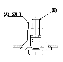
BCS adjustment procedure
1. At full boost pressure, set so that the full injection quantity is within the specifications (adjusting point).
2. Perform boost compensator intermediate operation point adjustment (pump speed N1, boost pressure P1).
3. When injection quantity at boost pressure P2 and pump speed N2 is not as specified, loosen nut (A) and adjust position of screw (B) so that injection quantity is as specified. The screw position should be within +-1 turn of initial position.
4. The nut tightening torque is T.
----------
N1=700r/min N2=500r/min P1=16.0kPa(120mmHg) P2=0kPa(0mmHg) T=6~9N-m(0.6~0.9kgf-m)
----------
SW=10mm T=6~9N-m(0.6~0.9kgf-m)
----------
N1=700r/min N2=500r/min P1=16.0kPa(120mmHg) P2=0kPa(0mmHg) T=6~9N-m(0.6~0.9kgf-m)
----------
SW=10mm T=6~9N-m(0.6~0.9kgf-m)
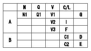
0000001801 POTENTIOMETER ADJUSTMENT
Potentiometer adjustment
1. Applied voltage: Vi
2. Boost pressure = P1
3. Set the control lever at the adjusting point. Position the dummy bolt against the lever and fix.
4. Assemble the potentiometer to obtain output voltage V1 at the fixed position.
5. After mounting the potentiometer, remove the dummy bolt.
A:Performance standards
B:ON, OFF switch standard
N:Pump speed
Q:Injection quantity
V:Output voltage
C/L: control lever position
I:Idle
F:Full speed
D:OFF-->ON
E:OFF-->ON
G:Adjusting point
----------
V1=3.3+-0.03V P1=0kPa(0mmHg) Vi=10.0V
----------
N1=700r/min Q1=24.7+-1.0mm3/st V1=3.3+-0.03V V2=1.48+-0.34V V3=(8.14+-0.74V) C1=(5.6+-2.6deg) C2=(20.1+-3deg)
----------
V1=3.3+-0.03V P1=0kPa(0mmHg) Vi=10.0V
----------
N1=700r/min Q1=24.7+-1.0mm3/st V1=3.3+-0.03V V2=1.48+-0.34V V3=(8.14+-0.74V) C1=(5.6+-2.6deg) C2=(20.1+-3deg)
Information:
Installation of Nozzles, Ether Supply Tubes and Connectors
1. If the machine does not already have an ether aid starting system, remove the plug from each turbocharger outlet adapter (2) and (3). Install a 3B6768 Bushing with a 7X1078 Nozzle Assembly (1) where each plug was removed. 2. When installing each nozzle assembly (1), the indicator mark at location (A) must be at the top as shown. Tighten the nozzle to a torque of 2.8 N m (25 lb in).3. Install 6Y1575 Tube Assembly (4) in the front nozzle and 6Y1576 Tube Assembly (6) in the rear nozzle as shown. Connect tube assemblies (4) and (6) to 8C9006 Tee (5). 4. Put 6Y1770 Tube Assembly (7) in position along the cylinder block and connect it to 8C9006 Tee (5) as shown. Install a 5P6312 Union (8) at the loose end as shown.5. Locate and attach 6V2686 Clips at locations (B) and (C), to secure tube (7) in position.6. Tighten the bolts that secure the clips at locations (B) and (C). 7. Put 5P0580 Tube (9) in position for connection to 5P6312 Union (8) that was JUST installed at the end of tube assembly (7). Position the tube assembly alongside chassis wiring harness (10) and up to the shuttle valve in cover assembly (11).Cut the 5P0580 Tube to length. Put a 5P6313 Nut and a 5P6314 Sleeve on the end of the piece of tube. Connect the end of the tube to union (8) and tighten the nut.
Be careful and DO NOT overtighten the nut. Overtightening the nut could crush the tube.
8. Use 3S2093 Straps (12) to fasten tube (9) to chassis wiring harness (10) [there are actually twelve straps between union (8) and the fender, and three straps inside of cover assembly (11)]. 9. Connect the end of tube (9) to elbow (13) in the outlet port of the shuttle valve. 10. If all welding procedures have been completed proceed as follows: * Apply the 9X4542 Ether Aid Identification Film (English) on the ECU. (If an Ether Aid Identification Film is needed for a language other than English, refer to the chart that follows for the part number to order to obtain a film with a specific language.) * Use four 5M3062 Bolts with 8T4896 Washers to fasten 9X5303 ECU (14) to the mounting bars inside cover assembly (11).* Connect the terminal on the loose end of fabricated wire assembly (15) (previously installed when mounting bars were installed inside the cover assembly) to one of the ECU mounting bolts as shown.* Connect the 30 pin connector of chassis wiring harness (10) to ECU (14).11. Use the dimensions shown to install 9X6191 Film (16).12. Put a 5P1075 Washer over the end of the 7S2043 Knob Assembly. Put the end of the knob assembly through the door of cover assembly (11). Install the 9S8230 Plate Assembly over the shaft of the knob assembly, then insert the 4H1641 Pin in the hole in the shaft.Installation of Ether Cylinders
1. Turn the disconnect switch