Information injection-pump assembly
ZEXEL
104760-4460
1047604460
NISSAN-DIESEL
1670051N04
1670051n04
Rating:
Cross reference number
ZEXEL
104760-4460
1047604460
NISSAN-DIESEL
1670051N04
1670051n04
Zexel num
Bosch num
Firm num
Name
Calibration Data:
Adjustment conditions
Test oil
1404 Test oil ISO4113orSAEJ967d
1404 Test oil ISO4113orSAEJ967d
Test oil temperature
degC
45
45
50
Nozzle
105780-0060
Bosch type code
NP-DN0SD1510
Nozzle holder
105780-2150
Opening pressure
MPa
13
13
13.3
Opening pressure
kgf/cm2
133
133
136
Injection pipe
157805-7320
Injection pipe
Inside diameter - outside diameter - length (mm) mm 2-6-450
Inside diameter - outside diameter - length (mm) mm 2-6-450
Joint assembly
157641-4720
Tube assembly
157641-4020
Transfer pump pressure
kPa
20
20
20
Transfer pump pressure
kgf/cm2
0.2
0.2
0.2
Direction of rotation (viewed from drive side)
Right R
Right R
(Solenoid timer adjustment condition)
With S/T O-ring; S/T OFF. OFF
With S/T O-ring; S/T OFF. OFF
Injection timing adjustment
Pump speed
r/min
500
500
500
Boost pressure
kPa
0
0
0
Boost pressure
mmHg
0
0
0
Average injection quantity
mm3/st.
46.3
45.8
46.8
Basic
*
Oil temperature
degC
48
46
50
Remarks
NA
NA
Injection timing adjustment_02
Pump speed
r/min
700
700
700
Boost pressure
kPa
16
14.7
17.3
Boost pressure
mmHg
120
110
130
Average injection quantity
mm3/st.
53.7
53.2
54.2
Basic
*
Oil temperature
degC
50
48
52
Remarks
CBS
CBS
Injection timing adjustment_03
Pump speed
r/min
1000
1000
1000
Boost pressure
kPa
53.3
52
54.6
Boost pressure
mmHg
400
390
410
Average injection quantity
mm3/st.
58.3
57.8
58.8
Difference in delivery
mm3/st.
4
Basic
*
Oil temperature
degC
50
48
52
Injection timing adjustment_04
Pump speed
r/min
500
500
500
Boost pressure
kPa
0
0
0
Boost pressure
mmHg
0
0
0
Average injection quantity
mm3/st.
46.3
45.3
47.3
Basic
*
Oil temperature
degC
48
46
50
Injection timing adjustment_05
Pump speed
r/min
700
700
700
Boost pressure
kPa
16
14.7
17.3
Boost pressure
mmHg
120
110
130
Average injection quantity
mm3/st.
53.7
52.7
54.7
Basic
*
Oil temperature
degC
50
48
52
Remarks
CBS
CBS
Injection timing adjustment_06
Pump speed
r/min
1000
1000
1000
Boost pressure
kPa
0
0
0
Boost pressure
mmHg
0
0
0
Average injection quantity
mm3/st.
51.1
48.6
53.6
Oil temperature
degC
50
48
52
Injection timing adjustment_07
Pump speed
r/min
1000
1000
1000
Boost pressure
kPa
53.3
52
54.6
Boost pressure
mmHg
400
390
410
Average injection quantity
mm3/st.
58.3
57.3
59.3
Difference in delivery
mm3/st.
4.5
Basic
*
Oil temperature
degC
50
48
52
Injection timing adjustment_08
Pump speed
r/min
2000
2000
2000
Boost pressure
kPa
53.3
52
54.6
Boost pressure
mmHg
400
390
410
Average injection quantity
mm3/st.
61.1
58.6
63.6
Oil temperature
degC
50
48
52
Injection quantity adjustment
Pump speed
r/min
2300
2300
2300
Boost pressure
kPa
53.3
52
54.6
Boost pressure
mmHg
400
390
410
Average injection quantity
mm3/st.
18.3
16.3
20.3
Basic
*
Oil temperature
degC
52
50
54
Injection quantity adjustment_02
Pump speed
r/min
2500
2500
2500
Boost pressure
kPa
53.3
52
54.6
Boost pressure
mmHg
400
390
410
Average injection quantity
mm3/st.
5
Oil temperature
degC
55
52
58
Injection quantity adjustment_03
Pump speed
r/min
2100
2100
2100
Boost pressure
kPa
53.3
52
54.6
Boost pressure
mmHg
400
390
410
Average injection quantity
mm3/st.
55.2
50.7
59.7
Oil temperature
degC
52
50
54
Injection quantity adjustment_04
Pump speed
r/min
2300
2300
2300
Boost pressure
kPa
53.3
52
54.6
Boost pressure
mmHg
400
390
410
Average injection quantity
mm3/st.
18.3
15.8
20.8
Basic
*
Oil temperature
degC
52
50
54
Governor adjustment
Pump speed
r/min
350
350
350
Boost pressure
kPa
0
0
0
Boost pressure
mmHg
0
0
0
Average injection quantity
mm3/st.
12.5
10.5
14.5
Difference in delivery
mm3/st.
2
Basic
*
Oil temperature
degC
48
46
50
Governor adjustment_02
Pump speed
r/min
350
350
350
Boost pressure
kPa
0
0
0
Boost pressure
mmHg
0
0
0
Average injection quantity
mm3/st.
12.5
10
15
Difference in delivery
mm3/st.
2.5
Basic
*
Oil temperature
degC
48
46
50
Timer adjustment
Pump speed
r/min
100
100
100
Boost pressure
kPa
0
0
0
Boost pressure
mmHg
0
0
0
Average injection quantity
mm3/st.
58
48
78
Basic
*
Oil temperature
degC
48
46
50
Remarks
Full
Full
Timer adjustment_02
Pump speed
r/min
100
100
100
Boost pressure
kPa
0
0
0
Boost pressure
mmHg
0
0
0
Average injection quantity
mm3/st.
58
48
78
Oil temperature
degC
48
46
50
Remarks
Full
Full
Speed control lever angle
Pump speed
r/min
350
350
350
Boost pressure
kPa
0
0
0
Boost pressure
mmHg
0
0
0
Average injection quantity
mm3/st.
0
0
0
Oil temperature
degC
48
46
50
Remarks
Magnet OFF at idling position
Magnet OFF at idling position
0000000901
Pump speed
r/min
1000
1000
1000
Boost pressure
kPa
53.3
52
54.6
Boost pressure
mmHg
400
390
410
Overflow quantity with S/T ON
cm3/min
420
290
550
Oil temperature
degC
50
48
52
Remarks
With an O-ring
With an O-ring
_02
Pump speed
r/min
1000
1000
1000
Boost pressure
kPa
53.3
52
54.6
Boost pressure
mmHg
400
390
410
Overflow quantity with S/T ON
cm3/min
470
340
600
Oil temperature
degC
50
48
52
Remarks
Without an O-ring
Without an O-ring
Stop lever angle
Pump speed
r/min
1000
1000
1000
Boost pressure
kPa
53.3
52
54.6
Boost pressure
mmHg
400
390
410
Pressure with S/T ON
kPa
431
392
470
Pressure with S/T ON
kgf/cm2
4.4
4
4.8
Pressure with S/T OFF
kPa
333
304
362
Pressure with S/T OFF
kgf/cm2
3.4
3.1
3.7
Basic
*
Oil temperature
degC
50
48
52
Stop lever angle_02
Pump speed
r/min
1000
1000
1000
Boost pressure
kPa
53.3
52
54.6
Boost pressure
mmHg
400
390
410
Pressure with S/T OFF
kPa
333
294
372
Pressure with S/T OFF
kgf/cm2
3.4
3
3.8
Basic
*
Oil temperature
degC
50
48
52
Stop lever angle_03
Pump speed
r/min
1700
1700
1700
Boost pressure
kPa
53.3
52
54.6
Boost pressure
mmHg
400
390
410
Pressure with S/T OFF
kPa
549
510
588
Pressure with S/T OFF
kgf/cm2
5.6
5.2
6
Oil temperature
degC
50
48
52
0000001101
Pump speed
r/min
1000
1000
1000
Boost pressure
kPa
53.3
52
54.6
Boost pressure
mmHg
400
390
410
Timer stroke with S/T ON
mm
4.8
4.4
5.2
Timer stroke with S/T OFF
mm
2.6
2.4
2.8
Basic
*
Oil temperature
degC
50
48
52
_02
Pump speed
r/min
800
800
800
Boost pressure
kPa
53.3
52
54.6
Boost pressure
mmHg
400
390
410
Timer stroke with S/T OFF
mm
1.1
0.6
1.6
Oil temperature
degC
50
48
52
_03
Pump speed
r/min
1000
1000
1000
Boost pressure
kPa
53.3
52
54.6
Boost pressure
mmHg
400
390
410
Timer stroke with S/T ON
mm
4.8
4.3
5.3
Timer stroke with S/T OFF
mm
2.6
2.3
2.9
Basic
*
Oil temperature
degC
50
48
52
_04
Pump speed
r/min
1700
1700
1700
Boost pressure
kPa
53.3
52
54.6
Boost pressure
mmHg
400
390
410
Timer stroke with S/T OFF
mm
7
6.5
7.4
Oil temperature
degC
50
48
52
_05
Pump speed
r/min
2000
2000
2000
Boost pressure
kPa
53.3
52
54.6
Boost pressure
mmHg
400
390
410
Timer stroke with S/T OFF
mm
7
6.5
7.4
Oil temperature
degC
50
48
52
0000001201
Max. applied voltage
V
8
8
8
Test voltage
V
13
12
14
0000001401
Pump speed
r/min
1000
1000
1000
Boost pressure
kPa
53.3
52
54.6
Boost pressure
mmHg
400
390
410
Average injection quantity
mm3/st.
38
37.5
38.5
Timer stroke TA
mm
2.3
2.3
2.3
Timer stroke variation dT
mm
0.3
0.1
0.5
Basic
*
Oil temperature
degC
50
48
52
_02
Pump speed
r/min
1000
1000
1000
Boost pressure
kPa
53.3
52
54.6
Boost pressure
mmHg
400
390
410
Average injection quantity
mm3/st.
38
37
39
Timer stroke variation dT
mm
0.3
0
0.6
Basic
*
Oil temperature
degC
50
48
52
_03
Pump speed
r/min
1000
1000
1000
Boost pressure
kPa
53.3
52
54.6
Boost pressure
mmHg
400
390
410
Average injection quantity
mm3/st.
26
23.5
28.5
Timer stroke variation dT
mm
0.8
0.4
1.2
Oil temperature
degC
50
48
52
Timing setting
K dimension
mm
3.3
3.2
3.4
KF dimension
mm
6.64
6.54
6.74
MS dimension
mm
1
0.9
1.1
BCS stroke
mm
1.8
1.6
2
Control lever angle alpha
deg.
10
6
14
Control lever angle beta
deg.
40
35
45
Test data Ex:
0000001601 BOOST COMPENSATOR ADJUSTMENT
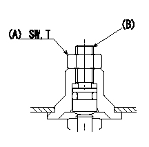
BCS adjustment procedure
1. At full boost pressure, set so that the full injection quantity is within the specifications (adjusting point).
2. Perform boost compensator intermediate operation point adjustment (pump speed N1, boost pressure P1).
3. When injection quantity at boost pressure P2 and pump speed N2 is not as specified, loosen nut (A) and adjust position of screw (B) so that injection quantity is as specified. The screw position should be within +-1 turn of initial position.
4. The nut tightening torque is T.
----------
N1=700r/min N2=500r/min P1=16.0kPa(120mmHg) P2=0kPa(0mmHg) T=6~9N-m(0.6~0.9kgf-m)
----------
SW=10mm T=6~9N-m(0.6~0.9kgf-m)
----------
N1=700r/min N2=500r/min P1=16.0kPa(120mmHg) P2=0kPa(0mmHg) T=6~9N-m(0.6~0.9kgf-m)
----------
SW=10mm T=6~9N-m(0.6~0.9kgf-m)
0000001801 POTENTIOMETER ADJUSTMENT
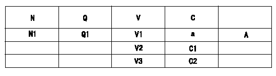
Potentiometer adjustment
1. Applied voltage: Vi
2. Boost pressure = P1
3. Set the control lever at the adjusting point. Position the dummy bolt against the lever and fix.
4. Assemble the potentiometer to obtain output voltage V1 at the fixed position.
5. After mounting the potentiometer, remove the dummy bolt.
N:Pump speed
Q:Injection quantity
V:Output voltage
C:Position of the control lever
A:Adjusting point
C1:Idle
C2:Full-speed
----------
V1=5.52+-0.03V P1=0kPa(0mmHg) Vi=10V
----------
N1=850r/min Q1=13.8+-1.0mm3/st V1=5.52+-0.03V V2=2.42+-0.78V V3=(10V) a=-
----------
V1=5.52+-0.03V P1=0kPa(0mmHg) Vi=10V
----------
N1=850r/min Q1=13.8+-1.0mm3/st V1=5.52+-0.03V V2=2.42+-0.78V V3=(10V) a=-
Information:
04Feb2016
U-58
A-46
D-55
O-52
Parts stock action only
PRODUCT IMPROVEMENT PROGRAM FOR REMOVING 398-1498 AND 463-1678 FUEL INJECTION PUMPS FROM DEALER PARTS STOCK
7750 PI70604
Caterpillar’s obligations under this Service Letter are subject to, and shall not apply in contravention of, the laws, rules, regulations, directives, ordinances, orders, or statutes of the United States, or of any other applicable jurisdiction, without recourse or liability with respect to Caterpillar.
When submitting claim for Parts Stock Action, Use the appropriate 99Z as the s/n, the appropriate Service Letter Program Number as the Part number in the Part Causing Failure field, "7751" as the Group Number, "56" as the Description Code.
The information supplied in this service letter may not be valid after the termination date of this program.Do not perform the work outlined in this Service Letter after the termination date without first contacting your Caterpillar product analyst.
TERMINATION DATE
31May2016
PROBLEM
The existing 398-1498 and 463-1678 Fuel Injection Pumps can fail. Fuel Injection Pumps up to and inclusive of component serial number 06369GJG, are suspect.
ACTION REQUIRED
Inspect all 398-1498 and 463-1678 Fuel Injection Pumps in dealer parts stock. Review the component serial number on each 398-1498 and 463-1678 Fuel Injection Pump. The Fuel Injection Pump component serial number can be located on the Fuel Injection Pump data plate, affixed to the side of the Fuel Injection Pump body.
The Fuel Injection Pump component serial number is alphanumeric, Refer to Image 1 for explanation on component serial number translation. In the given example the date code would translate to the following - 6369th pump built in July 2015.
NOTE - The build facility is not applicable in determining if the Fuel Injection Pump is suspect or not.
Refer to Image 2 for the build month and build year translation table.
Please action according to the following build month and build year color code -
Red = Remove from dealer part stock
Orange = Check Fuel Injection Pump Serial Number (06369 and below = Remove from dealer part stock / 06370 and Up = Return to dealer part stock).
Green = OK, Return to dealer part stock.
- If the Fuel Injection Pump is removed from dealer parts stock. Refer to the Service Claim Allowances and Parts Disposition.
- If the Fuel Injection Pump is returned to dealer parts stock, mark the box as inspected.
Image1
Image2
SERVICE CLAIM ALLOWANCES
Submit one claim for all Fuel Injection Pumps removed from dealer parts stock. Include the date code (e.g. 06369GJG) in the claim story for each Fuel Injection Pump removed from dealer parts stock.
PARTS DISPOSITION
NACD:
Hold all 398-1498 and 463-1678 Fuel Injection Pumps removed from dealer parts stock for a Parts Return Request (PRR). A Parts Return Request (PRR) will be issued to you through the Send-It-Back process after the claim is submitted. Make sure to list the service letter program number on the packing