Information injection-pump assembly
ZEXEL
104760-4440
1047604440
NISSAN-DIESEL
1670051N08
1670051n08
Rating:
Cross reference number
ZEXEL
104760-4440
1047604440
NISSAN-DIESEL
1670051N08
1670051n08
Zexel num
Bosch num
Firm num
Name
Calibration Data:
Adjustment conditions
Test oil
1404 Test oil ISO4113orSAEJ967d
1404 Test oil ISO4113orSAEJ967d
Test oil temperature
degC
45
45
50
Nozzle
105000-2010
Bosch type code
NP-DN12SD12TT
Nozzle holder
105780-2080
Opening pressure
MPa
14.7
14.7
15.19
Opening pressure
kgf/cm2
150
150
155
Injection pipe
Inside diameter - outside diameter - length (mm) mm 2-6-840
Inside diameter - outside diameter - length (mm) mm 2-6-840
Transfer pump pressure
kPa
20
20
20
Transfer pump pressure
kgf/cm2
0.2
0.2
0.2
Direction of rotation (viewed from drive side)
Right R
Right R
Injection timing adjustment
Pump speed
r/min
1000
1000
1000
Average injection quantity
mm3/st.
50.9
50.4
51.4
Difference in delivery
mm3/st.
3.5
Basic
*
Oil temperature
degC
50
48
52
Injection timing adjustment_02
Pump speed
r/min
600
600
600
Average injection quantity
mm3/st.
52.6
50.6
54.6
Oil temperature
degC
50
48
52
Injection timing adjustment_03
Pump speed
r/min
1000
1000
1000
Average injection quantity
mm3/st.
50.9
49.9
51.9
Difference in delivery
mm3/st.
4
Basic
*
Oil temperature
degC
50
48
52
Injection timing adjustment_04
Pump speed
r/min
2000
2000
2000
Average injection quantity
mm3/st.
44.7
42.6
46.8
Oil temperature
degC
52
50
54
Injection quantity adjustment
Pump speed
r/min
2300
2300
2300
Average injection quantity
mm3/st.
16.6
14.6
18.6
Difference in delivery
mm3/st.
5
Basic
*
Oil temperature
degC
52
50
54
Injection quantity adjustment_02
Pump speed
r/min
2500
2500
2500
Average injection quantity
mm3/st.
5
Oil temperature
degC
55
52
58
Injection quantity adjustment_03
Pump speed
r/min
2100
2100
2100
Average injection quantity
mm3/st.
43.8
39.3
48.3
Oil temperature
degC
52
50
54
Injection quantity adjustment_04
Pump speed
r/min
2300
2300
2300
Average injection quantity
mm3/st.
16.6
14.1
19.1
Basic
*
Oil temperature
degC
52
50
54
Governor adjustment
Pump speed
r/min
350
350
350
Average injection quantity
mm3/st.
8.8
6.8
10.8
Difference in delivery
mm3/st.
2
Basic
*
Oil temperature
degC
48
46
50
Governor adjustment_02
Pump speed
r/min
350
350
350
Average injection quantity
mm3/st.
8.8
6.3
11.3
Difference in delivery
mm3/st.
2.5
Basic
*
Oil temperature
degC
48
46
50
Timer adjustment
Pump speed
r/min
100
100
100
Average injection quantity
mm3/st.
60
50
80
Basic
*
Oil temperature
degC
48
46
50
Remarks
Full
Full
Timer adjustment_02
Pump speed
r/min
100
100
100
Average injection quantity
mm3/st.
60
50
80
Oil temperature
degC
48
46
50
Remarks
Full
Full
Speed control lever angle
Pump speed
r/min
350
350
350
Average injection quantity
mm3/st.
0
0
0
Oil temperature
degC
48
46
50
Remarks
Magnet OFF at idling position
Magnet OFF at idling position
Speed control lever angle_02
Pump speed
r/min
250
250
250
Average injection quantity
mm3/st.
5
Oil temperature
degC
48
46
50
Remarks
Magnet OFF at full-load position
Magnet OFF at full-load position
0000000901
Pump speed
r/min
1000
1000
1000
Overflow quantity with S/T ON
cm3/min
400
270
530
Oil temperature
degC
50
48
52
Stop lever angle
Pump speed
r/min
1000
1000
1000
Pressure
kPa
324
304
344
Pressure
kgf/cm2
3.3
3.1
3.5
Basic
*
Oil temperature
degC
50
48
52
Stop lever angle_02
Pump speed
r/min
1000
1000
1000
Pressure
kPa
324
295
353
Pressure
kgf/cm2
3.3
3
3.6
Basic
*
Oil temperature
degC
50
48
52
Stop lever angle_03
Pump speed
r/min
1800
1800
1800
Pressure
kPa
608
569
647
Pressure
kgf/cm2
6.2
5.8
6.6
Oil temperature
degC
50
48
52
0000001101
Pump speed
r/min
1000
1000
1000
Timer stroke
mm
1.6
1.4
1.8
Basic
*
Oil temperature
degC
50
48
52
_02
Pump speed
r/min
800
800
800
Timer stroke
mm
0.5
0
1
Oil temperature
degC
50
48
52
_03
Pump speed
r/min
1000
1000
1000
Timer stroke
mm
1.6
1.3
1.9
Basic
*
Oil temperature
degC
50
48
52
_04
Pump speed
r/min
1800
1800
1800
Timer stroke
mm
5.8
5.3
6.3
Oil temperature
degC
50
48
52
_05
Pump speed
r/min
2200
2200
2200
Timer stroke
mm
7.4
6.9
7.8
Oil temperature
degC
52
50
54
0000001201
Max. applied voltage
V
8
8
8
Test voltage
V
13
12
14
0000001401
Pump speed
r/min
1200
1200
1200
Average injection quantity
mm3/st.
22
21.5
22.5
Timer stroke TA
mm
2.5
2.3
2.7
Timer stroke variation dT
mm
0.1
0.1
0.1
Basic
*
Oil temperature
degC
50
48
52
_02
Pump speed
r/min
1200
1200
1200
Average injection quantity
mm3/st.
22
21
23
Timer stroke TA
mm
2.5
2.2
2.8
Basic
*
Oil temperature
degC
50
48
52
_03
Pump speed
r/min
1200
1200
1200
Average injection quantity
mm3/st.
15
12.5
17.5
Timer stroke TA
mm
2.1
1.4
2.8
Oil temperature
degC
50
48
52
Timing setting
K dimension
mm
3.3
3.2
3.4
KF dimension
mm
6.64
6.54
6.74
MS dimension
mm
1
0.9
1.1
Control lever angle alpha
deg.
25
23
27
Control lever angle beta
deg.
40
35
45
Test data Ex:
0000001801 POTENTIOMETER ADJUSTMENT
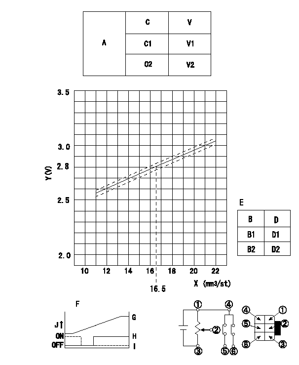
Adjustment of the potentiometer
At pump speed N1 and a control lever position a from idle (gap L1), measure the injection quantity and convert it to a voltage value. Then adjust the potentiometer.
Voltage conversion formula: V+-0.03 = 0.044Q+2.07
A:Potentiometer performance standards
C:Position of the control lever
C1:Idle
C2:Full speed
V:Potentiometer voltage
E:Standards for the potentiometer's ON - OFF switch
B:Conversion point
B1:OFF-->ON
B2:OFF-->ON
D:Lever opening (from idle)
Vi:Applied voltage
F:Connecting diagram for the potentiometer
G:Output when (2) and (3) connected.
H:When (4) or (6) connected: switch OFF to ON.
I:When (4) or (5) connected: switch ON to OFF.
J:Output
----------
N1=700r/min a=7.5deg L1=4.9mm Vi=10V
----------
V1=1.6+-0.4V V2=8.0+-0.55V D1=6.0+-3.5deg D2=19.5+-3.5deg Vi=10V
----------
N1=700r/min a=7.5deg L1=4.9mm Vi=10V
----------
V1=1.6+-0.4V V2=8.0+-0.55V D1=6.0+-3.5deg D2=19.5+-3.5deg Vi=10V
Information:
Before completing the attached Rework Procedure, review the safety actions in the Operation and Maintenance Manual for safety information and safe working practices before starting the rework.
If the head gasket has failed replace the head gasket and the fuel
injection pump.
If the head gasket has not failed replace the fuel injection pump only.
The 483-2326 Fuel Injection Pump has revised injection timing to reduce the peak cylinder pressure in the engine. It is essential that the pump is installed as per the Disassembly and Assembly, "Fuel Injection Pump - Install - Delphi DP210" to achieve the desired fuel injection timing.
SERVICE CLAIM ALLOWANCES
****Parts Stock****
Submit one claim for all parts removed from dealer parts stock.
****Affected Product****
Product smu/age whichever comes first Caterpillar Dealer Suggested Customer Suggested
Parts % Labor Hrs% Parts % Labor Hrs% Parts % Labor Hrs%
0-3000 hrs,
0-48 mo 100.0% 100.0% 0.0% 0.0% 0.0% 0.0%
This is a 5.5-hour job
For After failure, and additional 13.8 hours is allowed. A maximum of $100 will be allowed for machining of cylinder head face to achieve required surface finish after failure.
PARTS DISPOSITION
****Parts Stock****
Handle the parts in accordance with your Warranty Bulletin on warranty parts handling.
****Affected Product****
Handle the parts in accordance with your Warranty Bulletin on warranty parts handling.
Rework Procedure
If the head gasket has failed follow the rework procedure for both head gasket replacement and for fuel injection pump replacement
If the head gasket has not failed follow the rework procedure for fuel injection pump replacement only.
Head gasket replacement:
Confirm the head gasket has failed through removal of the cylinder head and visual inspection of the gasket. Remove cylinder head ? refer to Disassembly and Assembly, "Cylinder Head - Remove". Confirm head gasket has failed through visual inspection, as per the images shown in Image 1.1.1.
Clean the cylinder head face and the cylinder block face to remove any deposits on the gasket sealing surface using an appropriate cleaner. Do not use abrasive materials to remove the deposits during the cleaning process to ensure that the correct surface flatness is maintained.
Inspect cylinder head for flatness and distortion. Refer to Image 1.1.2 for surface finish. Refer to System Operation Testing and Adjusting, "Cylinder Head ? Inspect" for more information. Resurface the cylinder head if required as per Testing and Adjusting, "Cylinder Head ? Inspect".
Inspect cylinder block for surface finish on the top deck of the cylinder block. Refer to Image 1.1.2 for surface finish. If the cylinder block is within specifications, install a new 258-4946 Cylinder Head Gasket. If the block is not within specification, refer to Reuse And Salvage Guidelines, SEBF8076, "Specifications to Salvage Contact Surfaces of Cylinder Blocks" for more information.
Note: A 369-3705 Cylinder Head Gasket may be required, depending on reuse and salvage guidelines.
Follow Disassembly and Assembly, "Cylinder Head ? Install" with a new gasket as per above information.
Fuel injection pump replacement:
Follow Disassembly and Assembly, "Fuel Injection Pump - Remove - Delphi DP210". Do not reuse the fuel pump. Record removed fuel pump serial number in claim story. The fuel pump serial number is in the format "12345ABC".
Install the new 483-2326