Information injection-pump assembly
BOSCH
9 460 613 107
9460613107
ZEXEL
104760-4093
1047604093
Rating:
Components :
| 0. | INJECTION-PUMP ASSEMBLY | 104760-4093 |
| 1. | _ | |
| 2. | FUEL INJECTION PUMP | 104660-4092 |
| 3. | NUMBER PLATE | 146905-6500 |
| 4. | _ | |
| 5. | CAPSULE | |
| 6. | ADJUSTING DEVICE | |
| 7. | NOZZLE AND HOLDER ASSY | 105148-1121 |
| 8. | Nozzle and Holder | 16600-43G03 |
| 9. | Open Pre:MPa(Kqf/cm2) | 9.8{100} |
| 10. | NOZZLE-HOLDER | 105078-0050 |
| 11. | NOZZLE | 105007-1130 |
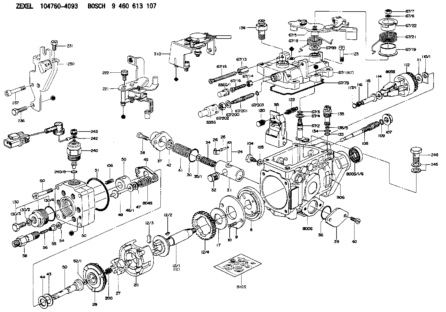
Scheme ###:
| 1/6. | [1] | 146601-0900 | PACKING RING |
| 6. | [1] | 146100-0420 | SUPPLY PUMP |
| 9. | [1] | 146103-0100 | COVER |
| 10. | [2] | 139104-0000 | FLAT-HEAD SCREW |
| 12. | [1] | 146200-0020 | DRIVE SHAFT |
| 12/1. | [1] | 146200-0000 | DRIVE SHAFT |
| 12/2. | [1] | 146201-0000 | WOODRUFF KEY |
| 12/3. | [2] | 146202-0100 | DAMPER |
| 12/4. | [1] | 146203-0000 | TOOTHED GEAR |
| 17. | [1] | 146204-0000 | PLAIN WASHER |
| 20. | [1] | 146210-2720 | ROLLER SET |
| 24. | [1] | 146303-0000 | BEARING PIN |
| 25. | [1] | 146304-0000 | BEARING PIN |
| 26. | [1] | 146305-0000 | CLAMPING BAND |
| 27. | [1] | 146205-0000 | SLOTTED WASHER |
| 29. | [1] | 146221-0120 | CAM PLATE |
| 30. | [1] | 146600-0800 | O-RING |
| 31. | [1] | 146311-6220 | PUMP PLUNGER |
| 32. | [1] | 146301-0000 | SLIDING PIECE |
| 34. | [1] | 146312-2600 | COMPRESSION SPRING |
| 35/1. | [1] | 146690-3200 | SHIM D11.5&9.4T0.1 |
| 35/1. | [1] | 146690-3300 | SHIM D11.5&9.4T0.2 |
| 35/1. | [1] | 146690-3400 | SHIM D11.5&9.4T0.25 |
| 35/1. | [1] | 146690-3500 | SHIM D11.5&9.4T1.0 |
| 35/1. | [1] | 146690-4100 | SHIM D11.5&9.4T2 |
| 35/1. | [1] | 146690-4200 | SHIM D11.5&9.4T0.5 |
| 35/1. | [1] | 146690-4300 | SHIM D11.5&9.4T0.75 |
| 36. | [1] | 146600-0800 | O-RING |
| 37. | [1] | 146310-1600 | COVER |
| 38. | [2] | 146620-5000 | BLEEDER SCREW |
| 39. | [1] | 146310-0100 | COVER |
| 40. | [2] | 146620-5000 | BLEEDER SCREW |
| 41. | [1] | 146312-1900 | COMPRESSION SPRING |
| 42. | [1] | 146602-8500 | PLAIN WASHER |
| 43. | [1] | 146230-0000 | SHIM |
| 44. | [1] | 146230-0100 | PLAIN WASHER |
| 45. | [1] | 146231-0000 | SLOTTED WASHER |
| 47. | [2] | 146233-0000 | SLOTTED WASHER |
| 48/1. | [1] | 146603-0000 | SHIM D17.0&5.2T0.50 |
| 48/1. | [1] | 146603-0100 | SHIM D17.0&5.2T0.80 |
| 48/1. | [1] | 146603-0200 | SHIM D17.0&5.2T1.00 |
| 48/1. | [1] | 146603-0300 | SHIM D17.0&5.2T1.20 |
| 48/1. | [1] | 146603-0400 | SHIM D17.0&5.2T1.50 |
| 48/1. | [1] | 146603-0500 | SHIM D17.0&5.2T1.80 |
| 48/1. | [1] | 146603-0600 | SHIM D17.0&5.2T2.00 |
| 48/1. | [1] | 146690-1400 | SHIM D17&5.2T0.9 |
| 48/1. | [1] | 146690-1500 | SHIM D17&5.2T1.1 |
| 48/1. | [1] | 146690-1600 | SHIM D17&5.2T1.3 |
| 48/1. | [1] | 146690-1700 | SHIM D17&5.2T1.4 |
| 48/1. | [1] | 146690-1800 | SHIM D17&5.2T1.6 |
| 48/1. | [1] | 146690-1900 | SHIM D17&5.2T1.7 |
| 48/1. | [1] | 146690-5800 | SHIM |
| 48/1. | [1] | 146690-5900 | SHIM |
| 48/1. | [1] | 146690-6000 | SHIM |
| 48/1. | [1] | 146690-6100 | SHIM |
| 48/1. | [1] | 146690-6200 | SHIM |
| 48/1. | [1] | 146690-6300 | SHIM |
| 48/1. | [1] | 146690-6400 | SHIM |
| 48/1. | [1] | 146690-6500 | SHIM |
| 48/1. | [1] | 146690-6600 | SHIM |
| 48/1. | [1] | 146690-6700 | SHIM |
| 48/1. | [1] | 146690-6800 | SHIM |
| 48/1. | [1] | 146690-6900 | SHIM |
| 48/1. | [1] | 146690-7000 | SHIM |
| 48/1. | [1] | 146690-7100 | SHIM |
| 48/1. | [1] | 146690-7200 | SHIM |
| 48/1. | [1] | 146690-7300 | SHIM |
| 48/1. | [1] | 146690-7400 | SHIM |
| 48/1. | [1] | 146690-7500 | SHIM |
| 48/1. | [1] | 146690-7800 | SHIM |
| 49. | [2] | 146234-0020 | GUIDE PIN |
| 50. | [1] | 146405-1920 | HYDRAULIC HEAD |
| 50. | [1] | 146405-1920 | HYDRAULIC HEAD |
| 50. | [1] | 146405-1920 | HYDRAULIC HEAD |
| 51. | [1] | 146600-0000 | O-RING |
| 52/1. | [1] | 146420-0000 | SHIM D9.5&3.0T1.90 |
| 52/1. | [1] | 146420-0100 | SHIM D9.5&3.0T1.92 |
| 52/1. | [1] | 146420-0200 | SHIM D9.5&3.0T1.94 |
| 52/1. | [1] | 146420-0300 | SHIM D9.5&3.0T1.96 |
| 52/1. | [1] | 146420-0400 | SHIM D9.5&3.0T1.98 |
| 52/1. | [1] | 146420-0500 | SHIM D9.5&3.0T2.00 |
| 52/1. | [1] | 146420-0600 | SHIM D9.5&3.0T2.02 |
| 52/1. | [1] | 146420-0700 | SHIM D9.5&3.0T2.04 |
| 52/1. | [1] | 146420-0800 | SHIM D9.5&3.0T2.06 |
| 52/1. | [1] | 146420-0900 | SHIM D9.5&3.0T2.08 |
| 52/1. | [1] | 146420-1000 | SHIM D9.5&3.0T2.10 |
| 52/1. | [1] | 146420-1100 | SHIM D9.5&3.0T2.12 |
| 52/1. | [1] | 146420-1200 | SHIM D9.5&3.0T2.14 |
| 52/1. | [1] | 146420-1300 | SHIM D9.5&3.0T2.16 |
| 52/1. | [1] | 146420-1400 | SHIM D9.5&3.0T2.18 |
| 52/1. | [1] | 146420-1500 | SHIM D9.5&3.0T2.20 |
| 52/1. | [1] | 146420-1600 | SHIM D9.5&3.0T2.22 |
| 52/1. | [1] | 146420-1700 | SHIM D9.5&3.0T2.24 |
| 52/1. | [1] | 146420-1800 | SHIM D9.5&3.0T2.26 |
| 52/1. | [1] | 146420-1900 | SHIM D9.5&3.0T2.28 |
| 52/1. | [1] | 146420-2000 | SHIM D9.5&3.0T2.30 |
| 52/1. | [1] | 146420-2100 | SHIM D9.5&3.0T2.32 |
| 52/1. | [1] | 146420-2200 | SHIM D9.5&3.0T2.34 |
| 52/1. | [1] | 146420-2300 | SHIM D9.5&3.0T2.36 |
| 52/1. | [1] | 146420-2400 | SHIM D9.5&3.0T2.38 |
| 52/1. | [1] | 146420-2500 | SHIM D9.5&3.0T2.40 |
| 52/1. | [1] | 146420-2600 | SHIM D9.5&3.0T2.42 |
| 52/1. | [1] | 146420-2700 | SHIM D9.5&3.0T2.44 |
| 52/1. | [1] | 146420-2800 | SHIM D9.5&3.0T2.46 |
| 52/1. | [1] | 146420-2900 | SHIM D9.5&3.0T2.48 |
| 52/1. | [1] | 146420-3000 | SHIM D9.5&3.0T2.50 |
| 52/1. | [1] | 146420-3100 | SHIM D9.5&3.0T2.52 |
| 52/1. | [1] | 146420-3200 | SHIM D9.5&3.0T2.54 |
| 52/1. | [1] | 146420-3300 | SHIM D9.5&3.0T2.56 |
| 52/1. | [1] | 146420-3400 | SHIM D9.5&3.0T2.58 |
| 52/1. | [1] | 146420-3500 | SHIM D9.5&3.0T2.60 |
| 52/1. | [1] | 146420-3600 | SHIM D9.5&3.0T2.62 |
| 52/1. | [1] | 146420-3700 | SHIM D9.5&3.0T2.64 |
| 52/1. | [1] | 146420-3800 | SHIM D9.5&3.0T2.66 |
| 52/1. | [1] | 146420-3900 | SHIM D9.5&3.0T2.68 |
| 52/1. | [1] | 146420-4000 | SHIM D9.5&3.0T2.70 |
| 52/1. | [1] | 146420-4100 | SHIM D9.5&3.0T2.72 |
| 52/1. | [1] | 146420-4200 | SHIM D9.5&3.0T2.74 |
| 52/1. | [1] | 146420-4300 | SHIM D9.5&3.0T2.76 |
| 52/1. | [1] | 146420-4400 | SHIM D9.5&3.0T2.78 |
| 52/1. | [1] | 146420-4500 | SHIM D9.5&3.0T2.80 |
| 52/1. | [1] | 146420-4600 | SHIM D9.5&3.0T2.82 |
| 52/1. | [1] | 146420-4700 | SHIM D9.5&3.0T2.84 |
| 52/1. | [1] | 146420-4800 | SHIM D9.5&3.0T2.86 |
| 52/1. | [1] | 146420-4900 | SHIM D9.5&3.0T2.88 |
| 52/1. | [1] | 146420-5000 | SHIM D9.5&3.0T2.90 |
| 52/1. | [1] | 146420-5100 | SHIM D9.5&3.0T1.74 |
| 52/1. | [1] | 146420-5200 | SHIM D9.5&3.0T1.76 |
| 52/1. | [1] | 146420-5300 | SHIM D9.5&3.0T1.78 |
| 52/1. | [1] | 146420-5400 | SHIM D9.5&3.0T1.80 |
| 52/1. | [1] | 146420-5500 | SHIM D9.5&3.0T1.82 |
| 52/1. | [1] | 146420-5600 | SHIM D9.5&3.0T1.84 |
| 52/1. | [1] | 146420-5700 | SHIM D9.5&3.0T1.86 |
| 52/1. | [1] | 146420-5800 | SHIM D9.5&3.0T1.88 |
| 54. | [6] | 146433-0100 | GASKET D12&6.4T1.00 |
| 55. | [6] | 146430-0320 | DELIVERY-VALVE ASSEMBLY |
| 56. | [6] | 146432-0000 | COMPRESSION SPRING |
| 58. | [6] | 146440-0220 | FITTING |
| 60. | [3] | 139106-0100 | FLAT-HEAD SCREW |
| 67. | [1] | 146501-5120 | GOVERNOR COVER |
| 67/1. | [1] | 146508-4521 | GOVERNOR COVER |
| 67/2. | [1] | 146515-3620 | CONTROL SHAFT |
| 67/3. | [1] | 146600-0100 | O-RING |
| 67/4. | [1] | 139310-0200 | PLAIN WASHER |
| 67/5. | [1] | 146537-6120 | CONTROL LEVER |
| 67/6. | [1] | 014110-6440 | LOCKING WASHER |
| 67/7. | [1] | 146621-0700 | UNION NUT |
| 67/13. | [1] | 146621-3100 | UNION NUT |
| 67/14. | [1] | 146621-1700 | UNION NUT |
| 67/15. | [1] | 146526-6400 | BLEEDER SCREW |
| 67/16. | [1] | 146526-3400 | BLEEDER SCREW |
| 67/18. | [1] | 146587-8000 | COILED SPRING |
| 67/19. | [1] | 146541-3000 | BUSHING |
| 67/21. | [1] | 146587-9900 | COILED SPRING |
| 67/22. | [1] | 146541-3100 | SLOTTED WASHER |
| 67/78. | [1] | 146600-4400 | SEAL RING |
| 67/89. | [1] | 146541-4900 | PLAIN WASHER D20&10T0.5 |
| 67/200. | [1] | 139308-0300 | PLAIN WASHER |
| 67/201. | [1] | 146545-3400 | THREADED PIN L53.00 |
| 67/201B. | [1] | 146545-3500 | THREADED PIN L55.00 |
| 67/201C. | [1] | 146545-3600 | THREADED PIN L57.00 |
| 67/202. | [1] | 139208-0900 | UNION NUT |
| 67/203. | [1] | 146600-1200 | O-RING |
| 95. | [1] | 146551-6920 | FULCRUM LEVER |
| 104. | [2] | 146568-0000 | SLOTTED SPRING PIN |
| 105. | [2] | 026508-1140 | GASKET D11.4&8.2T1 |
| 106. | [2] | 146588-0500 | COILED SPRING |
| 107. | [1] | 146569-0300 | UNION NUT |
| 108. | [1] | 146570-0100 | GOVERNOR SHAFT |
| 109. | [1] | 146600-0400 | O-RING |
| 110/1. | [1] | 146571-0000 | SHIM D20.2&8.3T1.05 |
| 110/1. | [1] | 146571-0100 | SHIM D20.2&8.3T1.25 |
| 110/1. | [1] | 146571-0200 | SHIM D20.2&8.3T1.45 |
| 110/1. | [1] | 146571-0300 | SHIM D20.2&8.3T1.65 |
| 110/1. | [1] | 146571-0400 | SHIM D20.2&8.3T1.85 |
| 110/1. | [1] | 146571-0500 | SHIM D20.2&8.3T1.15 |
| 110/1. | [1] | 146571-0600 | SHIM D20.2&8.3T1.35 |
| 110/1. | [1] | 146571-0700 | SHIM D20.2&8.3T1.55 |
| 110/1. | [1] | 146571-0800 | SHIM D20.2&8.3T1.75 |
| 111. | [1] | 146602-0600 | PLAIN WASHER D20&8.4T1.40 |
| 112. | [1] | 146572-0020 | FLYWEIGHT ASSEMBLY |
| 114. | [1] | 146602-0500 | PLAIN WASHER D17&6.4T1.60 |
| 115. | [1] | 146575-0600 | SLIDING SLEEVE |
| 116. | [1] | 146576-0000 | SEALING CAP |
| 117/1. | [1] | 146577-0000 | PLUG L1.70 |
| 117/1. | [1] | 146577-0100 | PLUG L1.90 |
| 117/1. | [1] | 146577-0200 | PLUG L2.10 |
| 117/1. | [1] | 146577-0300 | PLUG L2.30 |
| 117/1. | [1] | 146577-0400 | PLUG L2.50 |
| 117/1. | [1] | 146577-0500 | PLUG L2.70 |
| 117/1. | [1] | 146577-0600 | PLUG L2.90 |
| 117/1. | [1] | 146577-0700 | PLUG L3.10 |
| 117/1. | [1] | 146577-0800 | PLUG L3.30 |
| 117/1. | [1] | 146577-0900 | PLUG L3.50 |
| 117/1. | [1] | 146577-1000 | PLUG L3.70 |
| 117/1. | [1] | 146577-1100 | PLUG L3.90 |
| 117/1. | [1] | 146577-1200 | PLUG L4.10 |
| 117/1. | [1] | 146577-1300 | PLUG L4.30 |
| 117/1. | [1] | 146577-1400 | PLUG L4.50 |
| 117/1. | [1] | 146577-1500 | PLUG L4.70 |
| 117/1. | [1] | 146577-1600 | PLUG L4.90 |
| 117/1. | [1] | 146577-1700 | PLUG L5.10 |
| 117/1. | [1] | 146577-5000 | PLUG L1.8 |
| 117/1. | [1] | 146577-5100 | PLUG L2.0 |
| 117/1. | [1] | 146577-5200 | PLUG L2.2 |
| 117/1. | [1] | 146577-5300 | PLUG L2.4 |
| 117/1. | [1] | 146577-5400 | PLUG L2.6 |
| 117/1. | [1] | 146577-5500 | PLUG L2.8 |
| 117/1. | [1] | 146577-5600 | PLUG L3.0 |
| 117/1. | [1] | 146577-5700 | PLUG L3.2 |
| 117/1. | [1] | 146577-5800 | PLUG L3.4 |
| 117/1. | [1] | 146577-5900 | PLUG L3.6 |
| 117/1. | [1] | 146577-6000 | PLUG L3.8 |
| 117/1. | [1] | 146577-6100 | PLUG L4.0 |
| 117/1. | [1] | 146577-6200 | PLUG L4.2 |
| 117/1. | [1] | 146577-6300 | PLUG L4.4 |
| 117/1. | [1] | 146577-6400 | PLUG L4.6 |
| 117/1. | [1] | 146577-6500 | PLUG L4.8 |
| 117/1. | [1] | 146577-6600 | PLUG L5.0 |
| 117/1. | [1] | 146877-0400 | PLUG |
| 117/1. | [1] | 146877-0500 | PLUG |
| 117/1. | [1] | 146877-0600 | PLUG |
| 117/1. | [1] | 146877-0700 | PLUG |
| 117/1. | [1] | 146877-4300 | PLUG |
| 117/1. | [1] | 146877-4400 | PLUG |
| 117/1. | [1] | 146877-4500 | PLUG |
| 117/1. | [1] | 146877-4600 | PLUG |
| 120. | [1] | 146579-6520 | RETAINING PIN |
| 122. | [1] | 146580-1000 | GOVERNOR SPRING |
| 123. | [4] | 139106-0200 | FLAT-HEAD SCREW |
| 130. | [1] | 146421-0020 | CAPSULE |
| 130/2. | [1] | 026508-1140 | GASKET D11.4&8.2T1 |
| 130/3. | [1] | 146422-0000 | BLEEDER SCREW |
| 130/4. | [1] | 146600-0500 | O-RING |
| 133. | [1] | 146600-0600 | O-RING |
| 134. | [1] | 146600-0700 | O-RING |
| 135. | [1] | 146110-0220 | CONTROL VALVE |
| 135/5. | [1] | 146114-0000 | SPRING WASHER |
| 136. | [1] | 146120-0120 | OVER FLOW VALVE |
| 200. | [1] | 146206-0100 | COILED SPRING |
| 221. | [1] | 146925-7020 | BRACKET |
| 222. | [2] | 139006-4600 | BLEEDER SCREW |
| 230. | [1] | 146925-2720 | BRACKET |
| 231. | [1] | 139006-4600 | BLEEDER SCREW |
| 236. | [1] | 139006-4800 | BLEEDER SCREW |
| 237. | [1] | 146620-0200 | HEX-SOCKET-HEAD CAP SCREW |
| 240. | [1] | 146650-1220 | PULLING ELECTROMAGNET |
| 240/8. | [1] | 146600-1700 | O-RING |
| 242. | [1] | 146658-6120 | WIRE |
| 243. | [1] | 146621-1000 | UNION NUT |
| 245. | [2] | 026512-1840 | GASKET D17.9&12.2T1.50 |
| 246. | [1] | 027412-2440 | EYE BOLT |
| 310. | [1] | 146673-8620 | POTENTCIOMETER |
| 800S. | [1] | 146009-9220 | PUMP HOUSING |
| 800S/1/6. | [1] | 146601-0900 | PACKING RING |
| 804S. | [1] | 146232-0320 | COMPRESSION SPRING |
| 805S. | [1] | 146574-0120 | PARTS SET |
| 810S. | [1] | 146600-1120 | REPAIR SET |
| 835S. | [1] | 146598-1000 | CAP |
| 836S/1. | [1] | 146598-0600 | CAP L18 |
| 836S/1. | [1] | 146598-0700 | CAP L21 |
| 836S/1. | [1] | 146598-0800 | CAP L24 |
| 836S/1. | [1] | 146598-0900 | CAP L27 |
| 906. | [1] | 146905-6500 | NAMEPLATE |
Include in #2:
104760-4093
as INJECTION-PUMP ASSEMBLY
Cross reference number
BOSCH
9 460 613 107
9460613107
ZEXEL
104760-4093
1047604093
Zexel num
Bosch num
Firm num
Name
Calibration Data:
Adjustment conditions
Test oil
1404 Test oil ISO4113orSAEJ967d
1404 Test oil ISO4113orSAEJ967d
Test oil temperature
degC
45
45
50
Nozzle
105000-2010
Bosch type code
NP-DN12SD12TT
Nozzle holder
105780-2080
Opening pressure
MPa
14.7
14.7
15.19
Opening pressure
kgf/cm2
150
150
155
Injection pipe
Inside diameter - outside diameter - length (mm) mm 2-6-840
Inside diameter - outside diameter - length (mm) mm 2-6-840
Transfer pump pressure
kPa
20
20
20
Transfer pump pressure
kgf/cm2
0.2
0.2
0.2
Direction of rotation (viewed from drive side)
Right R
Right R
Injection timing adjustment
Pump speed
r/min
1000
1000
1000
Average injection quantity
mm3/st.
49.2
48.7
49.7
Difference in delivery
mm3/st.
3.5
Basic
*
Injection timing adjustment_02
Pump speed
r/min
2300
2300
2300
Average injection quantity
mm3/st.
16.7
14.2
19.2
Injection timing adjustment_03
Pump speed
r/min
2100
2100
2100
Average injection quantity
mm3/st.
41.7
37.2
46.2
Injection timing adjustment_04
Pump speed
r/min
2000
2000
2000
Average injection quantity
mm3/st.
43
40.9
45.1
Injection timing adjustment_05
Pump speed
r/min
1000
1000
1000
Average injection quantity
mm3/st.
49.2
48.2
50.2
Injection timing adjustment_06
Pump speed
r/min
600
600
600
Average injection quantity
mm3/st.
50.3
48.3
52.3
Injection quantity adjustment
Pump speed
r/min
2300
2300
2300
Average injection quantity
mm3/st.
16.7
14.7
18.7
Basic
*
Injection quantity adjustment_02
Pump speed
r/min
2500
2500
2500
Average injection quantity
mm3/st.
5
Governor adjustment
Pump speed
r/min
350
350
350
Average injection quantity
mm3/st.
8.8
6.8
10.8
Difference in delivery
mm3/st.
2
Basic
*
Governor adjustment_02
Pump speed
r/min
450
450
450
Average injection quantity
mm3/st.
3
Governor adjustment_03
Pump speed
r/min
350
350
350
Average injection quantity
mm3/st.
8.8
6.8
10.8
Timer adjustment
Pump speed
r/min
100
100
100
Average injection quantity
mm3/st.
65
50
80
Basic
*
Speed control lever angle
Pump speed
r/min
350
350
350
Average injection quantity
mm3/st.
0
0
0
Remarks
Magnet OFF
Magnet OFF
0000000901
Pump speed
r/min
1000
1000
1000
Overflow quantity
cm3/min
399
270
528
Stop lever angle
Pump speed
r/min
1000
1000
1000
Pressure
kPa
402
382
422
Pressure
kgf/cm2
4.1
3.9
4.3
Basic
*
Stop lever angle_02
Pump speed
r/min
1000
1000
1000
Pressure
kPa
402
382
422
Pressure
kgf/cm2
4.1
3.9
4.3
Stop lever angle_03
Pump speed
r/min
1600
1600
1600
Pressure
kPa
539.5
510
569
Pressure
kgf/cm2
5.5
5.2
5.8
Stop lever angle_04
Pump speed
r/min
1800
1800
1800
Pressure
kPa
598.5
569
628
Pressure
kgf/cm2
6.1
5.8
6.4
0000001101
Pump speed
r/min
1000
1000
1000
Timer stroke
mm
1.6
1.4
1.8
Basic
*
_02
Pump speed
r/min
1000
1000
1000
Timer stroke
mm
1.6
1.3
1.9
_03
Pump speed
r/min
1800
1800
1800
Timer stroke
mm
5.8
5.2
6.4
_04
Pump speed
r/min
2300
2300
2300
Timer stroke
mm
7.3
6.8
7.8
0000001201
Max. applied voltage
V
8
8
8
Test voltage
V
13
12
14
Timing setting
K dimension
mm
3.3
3.2
3.4
KF dimension
mm
6.64
6.54
6.74
MS dimension
mm
1
0.9
1.1
Control lever angle alpha
deg.
55.5
51.5
59.5
Control lever angle beta
deg.
40
35
45
Test data Ex:
0000001801 CONTROL LEVER ANGLE
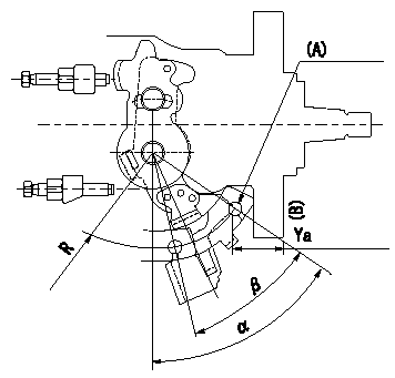
Control lever angle measurement
1. Measure dimension Ya between the end of the lever and the flange face.
2. Measure the lever angle from the pin hole R (plate).
(A) = lever angle and lever reaction force measuring position
----------
Ya=24.3~28.7mm R=53mm
----------
Ya=24.3~28.7mm R=53mm Alpha=51.5~59.5deg Beta=35~45deg
----------
Ya=24.3~28.7mm R=53mm
----------
Ya=24.3~28.7mm R=53mm Alpha=51.5~59.5deg Beta=35~45deg
0000001901 POTENTIOMETER ADJUSTMENT
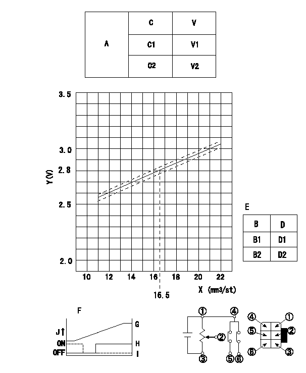
Adjustment of the potentiometer
Voltage conversion formula: V+-0.03 = xQ + y (V)
* Measure the injection quantity at N = N1r/min with the control lever position C3 (equivalent to L1 mm).
Determine the voltage with the conversion formula and adjust the potentiometer.
A:Performance standards for the potentiometer
B:Conversion point
C:Position of the control lever
D:Lever opening (from idle)
E:Standards for the potentiometer's ON/OFF switch
Vi:Applied voltage
V:Potentiometer voltage
X:Injection quantity: Q
Y:Voltage (V)
N1:Pump speed
C3:Position of the control lever
L1:Thickness of the shim
C1:Idle
C2:Full-speed
B1:ON-->OFF
B2:OFF-->ON
F:Connecting diagram for the potentiometer
G:Output when (2) and (3) connected.
H:When (4) or (6) connected: switch OFF to ON.
I:When (4) or (5) connected: switch ON to OFF.
J:Output
----------
x=0.044 y=2.07 N1=700r/min C3=7.5deg L1=4.9mm Vi=10V
----------
V1=1.6+-0.4V V2=8.0+-0.55V Vi=10V D1=6.0+-3.5deg D2=19.5+-3.5deg
----------
x=0.044 y=2.07 N1=700r/min C3=7.5deg L1=4.9mm Vi=10V
----------
V1=1.6+-0.4V V2=8.0+-0.55V Vi=10V D1=6.0+-3.5deg D2=19.5+-3.5deg
Information:
Action Required
See the attached procedure.
Service Claim Allowances
Group 1 Affected Product
All Group 2 Affected Product
This is a 1-hour job.
All Group 3 Affected Product
This is a .3-hour job. Submit a supplemental claim for Group 3 if a claim for Group 1 or 2 has already been submitted.
Parts Disposition
Handle the parts in accordance with your Warranty Bulletin on warranty parts handling.
Attach. (1-Rework Procedure)Rework Procedure
Refer to the following instructions and illustrations. Replace the existing fuel lines and their related parts with the new fuel line groups.
To insure correct clamp locations, install left and right fuel line groups as assembled. However, if clamps are removed, mark locations to insure correct positions when reassembling.
On the 992C Wheel Loader, it is necessary to remove the 6N8322 Air Outlet Tube Assembly to be able to install the right bank fuel line group.
Tighten the fuel line clamp screws to a torque of 2.25 N m (20 lb in). Do not over tighten. Use a 6V6069 Torque Screwdriver or similar tool to tighten the screws.
Group 1 Procedure
1. Clean and paint the new 6I0361 and 7E3539 Fuel Line Groups before proceeding to the job site.A) "Tape Off" the number 3, 5, and 6 fuel lines in the area of the tower clamp. (See Illustration 1 - Part 4 of 5, Section C-C)B) Install 5F2807 Plastic Caps and 2F2990 Plastic Plugs on the ends of the fuel lines.C) Clean and paint the fuel line groups.D) After drying completely, remove the tape. Do not remove the plastic caps and plugs until the fuel lines are ready to be installed on the engine. Transport the fuel line groups in their original boxes.2. Remove all mounting bolts from the fuel line brackets at the aftercooler housing. Except for the tower clamp assembly, new mounting bolts and washers will be used. Keep the washers. The washers may be needed later as spacers.3. A) Disassemble the tower clamp assembly behind the fuel injection pump. The 9Y3356 Clamp and 9Y3359 Clamp As. that form the tower clamp will be reused. (See Illustration 1 - Part 4 of 5, Section C-C)B) Disconnect the 2 line clamps from the 9Y3361 Bracket (Front V Bracket).C) Disconnect the 6 line clamps from the 7E5779 Bracket (Large V Bracket).4. Disconnect all the fuel lines at the fuel injection pump and at the adaptors in the valve cover bases.5. A) Remove the left and right side fuel line groups as separate assemblies.B) Remove the 9Y3361 Bracket (Front V Bracket). Replace it with a new 6I0347 Bracket.6. Remove the plastic caps and plugs from the fuel lines. Set the new 6I0361 Fuel Lines Group (left side) and the new 7E3539 Fuel Lines Group (right side) in place and hand tighten the fuel nuts. (See Illustration 1 - Part 1 of 5). If any of the ends of the individual fuel lines are not square with the bonnets in the fuel injection pump or with the adaptors in the valve cover bases, gently bend the lines by hand to align the