Information injection-pump assembly
ZEXEL
104760-4021
1047604021
NISSAN-DIESEL
1670006J02
1670006j02

Rating:
Cross reference number
ZEXEL
104760-4021
1047604021
NISSAN-DIESEL
1670006J02
1670006j02
Zexel num
Bosch num
Firm num
Name
Calibration Data:
Adjustment conditions
Test oil
1404 Test oil ISO4113orSAEJ967d
1404 Test oil ISO4113orSAEJ967d
Test oil temperature
degC
45
45
50
Nozzle
105000-2010
Bosch type code
NP-DN12SD12TT
Nozzle holder
105780-2080
Opening pressure
MPa
14.7
14.7
15.19
Opening pressure
kgf/cm2
150
150
155
Injection pipe
Inside diameter - outside diameter - length (mm) mm 2-6-840
Inside diameter - outside diameter - length (mm) mm 2-6-840
Transfer pump pressure
kPa
20
20
20
Transfer pump pressure
kgf/cm2
0.2
0.2
0.2
Direction of rotation (viewed from drive side)
Right R
Right R
Injection timing adjustment
Pump speed
r/min
1000
1000
1000
Average injection quantity
mm3/st.
51.2
50.7
51.7
Difference in delivery
mm3/st.
3.5
Basic
*
Injection timing adjustment_02
Pump speed
r/min
2300
2300
2300
Average injection quantity
mm3/st.
16.7
14.2
19.2
Injection timing adjustment_03
Pump speed
r/min
2100
2100
2100
Average injection quantity
mm3/st.
43.7
39.2
48.2
Injection timing adjustment_04
Pump speed
r/min
2000
2000
2000
Average injection quantity
mm3/st.
45
42.9
47.1
Injection timing adjustment_05
Pump speed
r/min
1600
1600
1600
Average injection quantity
mm3/st.
50.3
48.3
52.3
Injection timing adjustment_06
Pump speed
r/min
1300
1300
1300
Average injection quantity
mm3/st.
53
51
55
Injection timing adjustment_07
Pump speed
r/min
1000
1000
1000
Average injection quantity
mm3/st.
51.2
50.2
52.2
Injection timing adjustment_08
Pump speed
r/min
600
600
600
Average injection quantity
mm3/st.
52.3
50.3
54.3
Injection quantity adjustment
Pump speed
r/min
2300
2300
2300
Average injection quantity
mm3/st.
16.7
14.7
18.7
Basic
*
Injection quantity adjustment_02
Pump speed
r/min
2500
2500
2500
Average injection quantity
mm3/st.
5
Governor adjustment
Pump speed
r/min
350
350
350
Average injection quantity
mm3/st.
8.8
6.8
10.8
Difference in delivery
mm3/st.
2
Basic
*
Governor adjustment_02
Pump speed
r/min
350
350
350
Average injection quantity
mm3/st.
8.8
6.8
10.8
Governor adjustment_03
Pump speed
r/min
450
450
450
Average injection quantity
mm3/st.
3
Timer adjustment
Pump speed
r/min
100
100
100
Average injection quantity
mm3/st.
65
50
80
Basic
*
Speed control lever angle
Pump speed
r/min
350
350
350
Average injection quantity
mm3/st.
0
0
0
Remarks
Magnet OFF
Magnet OFF
0000000901
Pump speed
r/min
1000
1000
1000
Overflow quantity
cm3/min
399
270
528
Stop lever angle
Pump speed
r/min
1000
1000
1000
Pressure
kPa
402
382
422
Pressure
kgf/cm2
4.1
3.9
4.3
Basic
*
Stop lever angle_02
Pump speed
r/min
1000
1000
1000
Pressure
kPa
402
382
422
Pressure
kgf/cm2
4.1
3.9
4.3
Stop lever angle_03
Pump speed
r/min
1600
1600
1600
Pressure
kPa
539.5
510
569
Pressure
kgf/cm2
5.5
5.2
5.8
Stop lever angle_04
Pump speed
r/min
1800
1800
1800
Pressure
kPa
598.5
569
628
Pressure
kgf/cm2
6.1
5.8
6.4
0000001101
Pump speed
r/min
1000
1000
1000
Timer stroke
mm
1.6
1.4
1.8
Basic
*
_02
Pump speed
r/min
1000
1000
1000
Timer stroke
mm
1.6
1.3
1.9
_03
Pump speed
r/min
1800
1800
1800
Timer stroke
mm
5.8
5.2
6.4
_04
Pump speed
r/min
2300
2300
2300
Timer stroke
mm
7.3
6.8
7.8
0000001201
Max. applied voltage
V
8
8
8
Test voltage
V
13
12
14
Timing setting
K dimension
mm
3.3
3.2
3.4
KF dimension
mm
6.64
6.54
6.74
MS dimension
mm
1
0.9
1.1
Control lever angle alpha
deg.
55.5
51.5
59.5
Control lever angle beta
deg.
40
35
45
Test data Ex:
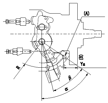
0000001801 CONTROL LEVER ANGLE

Control lever angle measurement
1. Measure dimension Ya between the end of the lever and the flange face.
2. Measure the lever angle from the pin hole R (plate).
(A) = lever angle and lever reaction force measuring position
----------
Ya=24.3~28.7mm R=53mm
----------
Ya=24.3~28.7mm R=53mm Alpha=51.5~59.5deg Beta=35~45deg
----------
Ya=24.3~28.7mm R=53mm
----------
Ya=24.3~28.7mm R=53mm Alpha=51.5~59.5deg Beta=35~45deg
Information:
6. Coat the seal of the element with a thin film of clean engine oil or antifreeze. 7. Install the element. Tighten it until the seal contacts the base, then tighten it an additional 3/4 turn. 8. Open the inlet valve and the outlet valve. 9. Maintain the coolant level above the low level plate. 10. Clean and install the radiator cap.11. Start the engine and check for leaks.Brakes
Inspect - Adjust
The machine must be level, the bowl lowered, and the parking brake applied.1. Block the wheels securely.2. Start the engine. 3. When the air pressure reaches the NORMAL range, stop the engine. 4. Release the parking/emergency brake. 5. Measure the distance from the rotochamber to the slack adjuster clevis retaining pin. 6. Apply the service brake and measure the amount of travel of the rod. If the travel is 76 mm (3 inches) or more, adjust the brake.7. Measure the brake rotochamber rod travel of all four wheel brakes. Scraper rotochambers are located inside the push frame.To Adjust
1. Loosen the adjustment locking bolt. 2. Turn the adjusting bolt, as required, until the travel is 41 mm (1.62 inches). 3. Tighten the locking bolt. 4. Apply and release the brakes, watching the rotochamber rod for binding.5. Observe the diaphragm for leaks. 6. Start the engine and allow air pressure to reach 690 kPa (100 psi) or in the green range on the air pressure gauge.7. Apply the parking brake.8. Stop the engine.9. Remove the blocking from the wheels.Check the Air System for Leaks
1. Start the engine and allow air pressure to reach 690 kPa (100 psi) or in the green range on the air pressure gauge. 2. Apply the service brakes and hold them in the applied condition.3. Stop the engine.4. With the brakes applied, watch the air pressure gauge.5. The pressure should drop no more than 35 kPa (5 psi) in 10 minutes.6. If the air pressure loss is greater than 35 kPa (5 psi), inspect the air lines and connections. Make any necessary repairs.To Test Brakes
Be sure the area around the vehicle is clear of personnel and obstructions.Fasten the seat belt before operating the vehicle.Test the brakes on a dry, level surface.
The vehicle must be on a dry, level surface, the bowl lowered and the parking brake applied.The following tests are to determine if the service brake or parking/emergency brake is functional. These tests are not intended to measure maximum brake holding effort.Brake holding effort required to hold a vehicle at a specific engine rpm will vary from vehicle to vehicle due to differences in engine setting, power train efficiency, etc., as well as differences in brake holding ability.Engine rpm at beginning of vehicle movement, with service or parking/emergency brake applied, should be compared against the engine rpm your specific vehicle was able to hold on a prior test, as an indication of system deterioration.Service Brake
1. Start the engine. Allow the engine to reach the normal operating temperature.2. When air pressure registers 690 kPa (100 psi) or