Information injection-pump assembly
BOSCH
9 460 613 091
9460613091
ZEXEL
104760-2553
1047602553
NISSAN
167001H901
167001h901
Rating:
Components :
| 0. | INJECTION-PUMP ASSEMBLY | 104760-2553 |
| 1. | _ | |
| 2. | FUEL INJECTION PUMP | 104660-2553 |
| 3. | NUMBER PLATE | 146915-2900 |
| 4. | _ | |
| 5. | CAPSULE | |
| 6. | ADJUSTING DEVICE | 146679-0720 |
| 7. | NOZZLE AND HOLDER ASSY | 105141-2991 |
| 8. | Nozzle and Holder | 16600-84T07 |
| 9. | Open Pre:MPa(Kqf/cm2) | 12.7{130} |
| 10. | NOZZLE-HOLDER | 105071-0681 |
| 11. | NOZZLE | 105000-2200 |
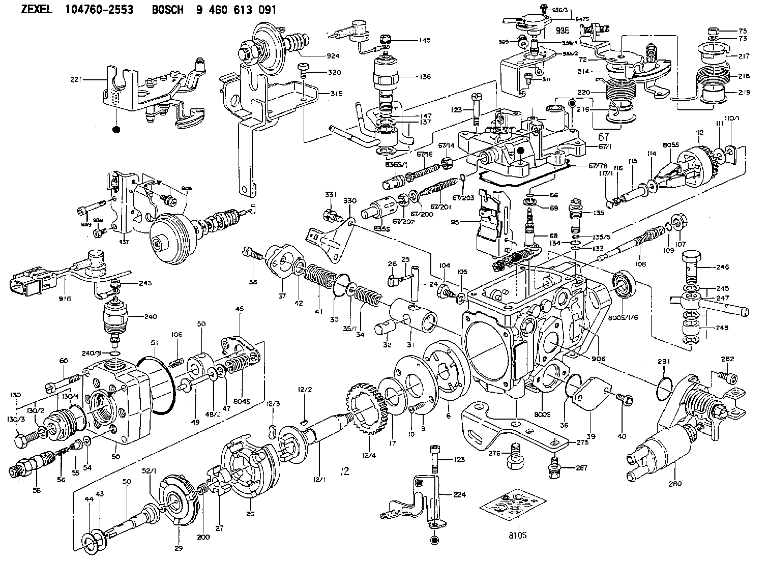
Scheme ###:
| 1/6. | [1] | 146601-0700 | PACKING RING |
| 6. | [1] | 146100-0220 | SUPPLY PUMP |
| 9. | [1] | 146103-0100 | COVER |
| 10. | [2] | 139104-0000 | FLAT-HEAD SCREW |
| 12. | [1] | 146200-0420 | DRIVE SHAFT |
| 12/1. | [1] | 146200-0400 | DRIVE SHAFT |
| 12/2. | [1] | 146201-0000 | WOODRUFF KEY |
| 12/3. | [2] | 146202-0100 | DAMPER |
| 12/4. | [1] | 146203-0000 | TOOTHED GEAR |
| 17. | [1] | 146204-0000 | PLAIN WASHER |
| 20. | [1] | 146210-3420 | ROLLER SET |
| 24. | [1] | 146303-0000 | BEARING PIN |
| 25. | [1] | 146304-0000 | BEARING PIN |
| 26. | [1] | 146305-0000 | CLAMPING BAND |
| 27. | [1] | 146205-0000 | SLOTTED WASHER |
| 29. | [1] | 146221-1120 | CAM PLATE |
| 30. | [1] | 146600-0800 | O-RING |
| 31. | [1] | 146311-8620 | PUMP PLUNGER |
| 32. | [1] | 146301-0200 | SLIDING PIECE |
| 34. | [1] | 146312-3900 | COMPRESSION SPRING |
| 34B. | [1] | 146312-4000 | COMPRESSION SPRING |
| 35/1. | [1] | 146690-3200 | SHIM D11.5&9.4T0.1 |
| 35/1. | [1] | 146690-3300 | SHIM D11.5&9.4T0.2 |
| 35/1. | [1] | 146690-3400 | SHIM D11.5&9.4T0.25 |
| 35/1. | [1] | 146690-3500 | SHIM D11.5&9.4T1.0 |
| 35/1. | [1] | 146690-4100 | SHIM D11.5&9.4T2 |
| 35/1. | [1] | 146690-4200 | SHIM D11.5&9.4T0.5 |
| 35/1. | [1] | 146690-4300 | SHIM D11.5&9.4T0.75 |
| 36. | [1] | 146600-0800 | O-RING |
| 37. | [1] | 146310-1600 | COVER |
| 38. | [2] | 146620-5000 | BLEEDER SCREW |
| 39. | [1] | 146310-0100 | COVER |
| 40. | [2] | 146620-5000 | BLEEDER SCREW |
| 41. | [1] | 146312-4100 | COMPRESSION SPRING |
| 42. | [1] | 146602-8500 | PLAIN WASHER |
| 43. | [1] | 146230-0000 | SHIM |
| 44. | [1] | 146230-0100 | PLAIN WASHER |
| 45. | [1] | 146231-0001 | SLOTTED WASHER |
| 47. | [2] | 146233-0000 | SLOTTED WASHER |
| 48/1. | [1] | 146603-0000 | SHIM D17.0&5.2T0.50 |
| 48/1. | [1] | 146603-0100 | SHIM D17.0&5.2T0.80 |
| 48/1. | [1] | 146603-0200 | SHIM D17.0&5.2T1.00 |
| 48/1. | [1] | 146603-0300 | SHIM D17.0&5.2T1.20 |
| 48/1. | [1] | 146603-0400 | SHIM D17.0&5.2T1.50 |
| 48/1. | [1] | 146603-0500 | SHIM D17.0&5.2T1.80 |
| 48/1. | [1] | 146603-0600 | SHIM D17.0&5.2T2.00 |
| 48/1. | [1] | 146690-1400 | SHIM D17&5.2T0.9 |
| 48/1. | [1] | 146690-1500 | SHIM D17&5.2T1.1 |
| 48/1. | [1] | 146690-1600 | SHIM D17&5.2T1.3 |
| 48/1. | [1] | 146690-1700 | SHIM D17&5.2T1.4 |
| 48/1. | [1] | 146690-1800 | SHIM D17&5.2T1.6 |
| 48/1. | [1] | 146690-1900 | SHIM D17&5.2T1.7 |
| 48/1. | [1] | 146690-5800 | SHIM |
| 48/1. | [1] | 146690-5900 | SHIM |
| 48/1. | [1] | 146690-6000 | SHIM |
| 48/1. | [1] | 146690-6100 | SHIM |
| 48/1. | [1] | 146690-6200 | SHIM |
| 48/1. | [1] | 146690-6300 | SHIM |
| 48/1. | [1] | 146690-6400 | SHIM |
| 48/1. | [1] | 146690-6500 | SHIM |
| 48/1. | [1] | 146690-6600 | SHIM |
| 48/1. | [1] | 146690-6700 | SHIM |
| 48/1. | [1] | 146690-6800 | SHIM |
| 48/1. | [1] | 146690-6900 | SHIM |
| 48/1. | [1] | 146690-7000 | SHIM |
| 48/1. | [1] | 146690-7100 | SHIM |
| 48/1. | [1] | 146690-7200 | SHIM |
| 48/1. | [1] | 146690-7300 | SHIM |
| 48/1. | [1] | 146690-7400 | SHIM |
| 48/1. | [1] | 146690-7500 | SHIM |
| 48/1. | [1] | 146690-7800 | SHIM |
| 49. | [2] | 146234-0120 | GUIDE PIN |
| 50. | [1] | 146405-2720 | HYDRAULIC HEAD |
| 50. | [1] | 146405-2720 | HYDRAULIC HEAD |
| 50. | [1] | 146405-2720 | HYDRAULIC HEAD |
| 51. | [1] | 146600-0000 | O-RING |
| 52/1. | [1] | 146420-0000 | SHIM D9.5&3.0T1.90 |
| 52/1. | [1] | 146420-0100 | SHIM D9.5&3.0T1.92 |
| 52/1. | [1] | 146420-0200 | SHIM D9.5&3.0T1.94 |
| 52/1. | [1] | 146420-0300 | SHIM D9.5&3.0T1.96 |
| 52/1. | [1] | 146420-0400 | SHIM D9.5&3.0T1.98 |
| 52/1. | [1] | 146420-0500 | SHIM D9.5&3.0T2.00 |
| 52/1. | [1] | 146420-0600 | SHIM D9.5&3.0T2.02 |
| 52/1. | [1] | 146420-0700 | SHIM D9.5&3.0T2.04 |
| 52/1. | [1] | 146420-0800 | SHIM D9.5&3.0T2.06 |
| 52/1. | [1] | 146420-0900 | SHIM D9.5&3.0T2.08 |
| 52/1. | [1] | 146420-1000 | SHIM D9.5&3.0T2.10 |
| 52/1. | [1] | 146420-1100 | SHIM D9.5&3.0T2.12 |
| 52/1. | [1] | 146420-1200 | SHIM D9.5&3.0T2.14 |
| 52/1. | [1] | 146420-1300 | SHIM D9.5&3.0T2.16 |
| 52/1. | [1] | 146420-1400 | SHIM D9.5&3.0T2.18 |
| 52/1. | [1] | 146420-1500 | SHIM D9.5&3.0T2.20 |
| 52/1. | [1] | 146420-1600 | SHIM D9.5&3.0T2.22 |
| 52/1. | [1] | 146420-1700 | SHIM D9.5&3.0T2.24 |
| 52/1. | [1] | 146420-1800 | SHIM D9.5&3.0T2.26 |
| 52/1. | [1] | 146420-1900 | SHIM D9.5&3.0T2.28 |
| 52/1. | [1] | 146420-2000 | SHIM D9.5&3.0T2.30 |
| 52/1. | [1] | 146420-2100 | SHIM D9.5&3.0T2.32 |
| 52/1. | [1] | 146420-2200 | SHIM D9.5&3.0T2.34 |
| 52/1. | [1] | 146420-2300 | SHIM D9.5&3.0T2.36 |
| 52/1. | [1] | 146420-2400 | SHIM D9.5&3.0T2.38 |
| 52/1. | [1] | 146420-2500 | SHIM D9.5&3.0T2.40 |
| 52/1. | [1] | 146420-2600 | SHIM D9.5&3.0T2.42 |
| 52/1. | [1] | 146420-2700 | SHIM D9.5&3.0T2.44 |
| 52/1. | [1] | 146420-2800 | SHIM D9.5&3.0T2.46 |
| 52/1. | [1] | 146420-2900 | SHIM D9.5&3.0T2.48 |
| 52/1. | [1] | 146420-3000 | SHIM D9.5&3.0T2.50 |
| 52/1. | [1] | 146420-3100 | SHIM D9.5&3.0T2.52 |
| 52/1. | [1] | 146420-3200 | SHIM D9.5&3.0T2.54 |
| 52/1. | [1] | 146420-3300 | SHIM D9.5&3.0T2.56 |
| 52/1. | [1] | 146420-3400 | SHIM D9.5&3.0T2.58 |
| 52/1. | [1] | 146420-3500 | SHIM D9.5&3.0T2.60 |
| 52/1. | [1] | 146420-3600 | SHIM D9.5&3.0T2.62 |
| 52/1. | [1] | 146420-3700 | SHIM D9.5&3.0T2.64 |
| 52/1. | [1] | 146420-3800 | SHIM D9.5&3.0T2.66 |
| 52/1. | [1] | 146420-3900 | SHIM D9.5&3.0T2.68 |
| 52/1. | [1] | 146420-4000 | SHIM D9.5&3.0T2.70 |
| 52/1. | [1] | 146420-4100 | SHIM D9.5&3.0T2.72 |
| 52/1. | [1] | 146420-4200 | SHIM D9.5&3.0T2.74 |
| 52/1. | [1] | 146420-4300 | SHIM D9.5&3.0T2.76 |
| 52/1. | [1] | 146420-4400 | SHIM D9.5&3.0T2.78 |
| 52/1. | [1] | 146420-4500 | SHIM D9.5&3.0T2.80 |
| 52/1. | [1] | 146420-4600 | SHIM D9.5&3.0T2.82 |
| 52/1. | [1] | 146420-4700 | SHIM D9.5&3.0T2.84 |
| 52/1. | [1] | 146420-4800 | SHIM D9.5&3.0T2.86 |
| 52/1. | [1] | 146420-4900 | SHIM D9.5&3.0T2.88 |
| 52/1. | [1] | 146420-5000 | SHIM D9.5&3.0T2.90 |
| 52/1. | [1] | 146420-5100 | SHIM D9.5&3.0T1.74 |
| 52/1. | [1] | 146420-5200 | SHIM D9.5&3.0T1.76 |
| 52/1. | [1] | 146420-5300 | SHIM D9.5&3.0T1.78 |
| 52/1. | [1] | 146420-5400 | SHIM D9.5&3.0T1.80 |
| 52/1. | [1] | 146420-5500 | SHIM D9.5&3.0T1.82 |
| 52/1. | [1] | 146420-5600 | SHIM D9.5&3.0T1.84 |
| 52/1. | [1] | 146420-5700 | SHIM D9.5&3.0T1.86 |
| 52/1. | [1] | 146420-5800 | SHIM D9.5&3.0T1.88 |
| 54. | [6] | 146433-0100 | GASKET D12&6.4T1.00 |
| 55. | [6] | 146430-4620 | DELIVERY-VALVE ASSEMBLY |
| 56. | [6] | 146432-0000 | COMPRESSION SPRING |
| 58. | [6] | 146440-0220 | FITTING |
| 60. | [3] | 139106-0100 | FLAT-HEAD SCREW |
| 66. | [1] | 146600-0100 | O-RING |
| 67. | [1] | 146503-8620 | GOVERNOR COVER |
| 67/1. | [1] | 146805-8020 | GOVERNOR COVER |
| 67/14. | [1] | 146621-1700 | UNION NUT |
| 67/16. | [1] | 146526-3400 | BLEEDER SCREW |
| 67/78. | [1] | 146600-4400 | SEAL RING |
| 67/200. | [1] | 139308-0300 | PLAIN WASHER |
| 67/201. | [1] | 146545-3400 | THREADED PIN L53.00 |
| 67/201B. | [1] | 146545-3500 | THREADED PIN L55.00 |
| 67/201C. | [1] | 146545-3600 | THREADED PIN L57.00 |
| 67/202. | [1] | 139208-0900 | UNION NUT |
| 67/203. | [1] | 146600-1200 | O-RING |
| 68. | [1] | 146514-5220 | CONTROL SHAFT |
| 69. | [1] | 139310-0200 | PLAIN WASHER |
| 72. | [1] | 146831-0220 | CONTROL LEVER |
| 72B. | [1] | 146831-0320 | CONTROL LEVER |
| 73. | [1] | 014110-6440 | LOCKING WASHER |
| 75. | [1] | 013020-6040 | UNION NUT M6P1H5 |
| 95. | [1] | 146861-1020 | FULCRUM LEVER |
| 104. | [2] | 146568-0000 | SLOTTED SPRING PIN |
| 105. | [2] | 026508-1140 | GASKET D11.4&8.2T1 |
| 106. | [2] | 146588-0500 | COILED SPRING |
| 107. | [1] | 146569-0300 | UNION NUT |
| 108. | [1] | 146570-0100 | GOVERNOR SHAFT |
| 109. | [1] | 146600-0400 | O-RING |
| 110/1. | [1] | 146571-0000 | SHIM D20.2&8.3T1.05 |
| 110/1. | [1] | 146571-0100 | SHIM D20.2&8.3T1.25 |
| 110/1. | [1] | 146571-0200 | SHIM D20.2&8.3T1.45 |
| 110/1. | [1] | 146571-0300 | SHIM D20.2&8.3T1.65 |
| 110/1. | [1] | 146571-0400 | SHIM D20.2&8.3T1.85 |
| 110/1. | [1] | 146571-0500 | SHIM D20.2&8.3T1.15 |
| 110/1. | [1] | 146571-0600 | SHIM D20.2&8.3T1.35 |
| 110/1. | [1] | 146571-0700 | SHIM D20.2&8.3T1.55 |
| 110/1. | [1] | 146571-0800 | SHIM D20.2&8.3T1.75 |
| 111. | [1] | 146602-0600 | PLAIN WASHER D20&8.4T1.40 |
| 112. | [1] | 146572-0020 | FLYWEIGHT ASSEMBLY |
| 114. | [1] | 146602-0500 | PLAIN WASHER D17&6.4T1.60 |
| 115. | [1] | 146575-2000 | SLIDING SLEEVE |
| 116. | [1] | 146576-0200 | CAP |
| 117/1. | [1] | 146577-1800 | PLUG L2.10 |
| 117/1. | [1] | 146577-1900 | PLUG L2.30 |
| 117/1. | [1] | 146577-2000 | PLUG L2.50 |
| 117/1. | [1] | 146577-2100 | PLUG L2.70 |
| 117/1. | [1] | 146577-2200 | PLUG L2.90 |
| 117/1. | [1] | 146577-2300 | PLUG L3.10 |
| 117/1. | [1] | 146577-2400 | PLUG L3.30 |
| 117/1. | [1] | 146577-2500 | PLUG L3.50 |
| 117/1. | [1] | 146577-2600 | PLUG L3.70 |
| 117/1. | [1] | 146577-2700 | PLUG L3.90 |
| 117/1. | [1] | 146577-2800 | PLUG L4.10 |
| 117/1. | [1] | 146577-2900 | PLUG L4.30 |
| 117/1. | [1] | 146577-3000 | PLUG L4.50 |
| 117/1. | [1] | 146577-3100 | PLUG L4.70 |
| 117/1. | [1] | 146577-3200 | PLUG L4.90 |
| 117/1. | [1] | 146577-3300 | PLUG L5.10 |
| 117/1. | [1] | 146577-6700 | PLUG L2.2 |
| 117/1. | [1] | 146577-6800 | PLUG L2.4 |
| 117/1. | [1] | 146577-6900 | PLUG L2.6 |
| 117/1. | [1] | 146577-7000 | PLUG L2.8 |
| 117/1. | [1] | 146577-7100 | PLUG L3.0 |
| 117/1. | [1] | 146577-7200 | PLUG L3.2 |
| 117/1. | [1] | 146577-7300 | PLUG L3.4 |
| 117/1. | [1] | 146577-7400 | PLUG L3.6 |
| 117/1. | [1] | 146577-7500 | PLUG L3.8 |
| 117/1. | [1] | 146577-7600 | PLUG L4.0 |
| 117/1. | [1] | 146577-7700 | PLUG L4.2 |
| 117/1. | [1] | 146577-7800 | PLUG L4.4 |
| 117/1. | [1] | 146577-7900 | PLUG L4.6 |
| 117/1. | [1] | 146577-8000 | PLUG L4.8 |
| 117/1. | [1] | 146577-8100 | PLUG L5.0 |
| 117/1. | [1] | 146877-0000 | PLUG L5.2 |
| 117/1. | [1] | 146877-0100 | PLUG L5.3 |
| 117/1. | [1] | 146877-0200 | PLUG L5.4 |
| 117/1. | [1] | 146877-0300 | PLUG L5.5 |
| 117/1. | [1] | 146877-4700 | PLUG |
| 117/1. | [1] | 146877-4800 | PLUG |
| 117/1. | [1] | 146877-4900 | PLUG |
| 117/1. | [1] | 146877-5000 | PLUG |
| 123. | [4] | 139106-0200 | FLAT-HEAD SCREW |
| 123. | [4] | 139106-0200 | FLAT-HEAD SCREW |
| 130. | [1] | 146421-0020 | CAPSULE |
| 130/2. | [1] | 026508-1140 | GASKET D11.4&8.2T1 |
| 130/3. | [1] | 146422-0000 | BLEEDER SCREW |
| 130/4. | [1] | 146600-0500 | O-RING |
| 133. | [1] | 146600-0600 | O-RING |
| 134. | [1] | 146600-0700 | O-RING |
| 135. | [1] | 146110-0220 | CONTROL VALVE |
| 135/5. | [1] | 146114-0000 | SPRING WASHER |
| 136. | [1] | 146650-6020 | PULLING ELECTROMAGNET |
| 136B. | [1] | 146650-5420 | PULLING ELECTROMAGNET |
| 136C. | [1] | 146650-6320 | PULLING ELECTROMAGNET |
| 137. | [2] | 139514-0200 | GASKET |
| 145. | [1] | 146621-1000 | UNION NUT |
| 147. | [1] | 016520-1210 | O-RING |
| 200. | [1] | 146206-0100 | COILED SPRING |
| 214. | [1] | 146542-5000 | BUSHING |
| 216. | [1] | 146542-5100 | BUSHING |
| 217. | [1] | 146541-3100 | SLOTTED WASHER |
| 218. | [1] | 146592-5600 | COILED SPRING |
| 219. | [1] | 146541-3000 | BUSHING |
| 220. | [1] | 146592-5700 | COILED SPRING |
| 221. | [1] | 146627-4420 | BRACKET |
| 224. | [1] | 146925-0300 | BRACKET |
| 240. | [1] | 146650-0720 | PULLING ELECTROMAGNET |
| 240/8. | [1] | 146600-1700 | O-RING |
| 243. | [1] | 146621-1000 | UNION NUT |
| 245. | [3] | 139512-0200 | GASKET D18.5&12.2T1.00 |
| 246. | [1] | 139812-0500 | EYE BOLT |
| 247. | [1] | 146666-5221 | PIPE |
| 248. | [1] | 146614-0200 | SPACER BUSHING |
| 275. | [1] | 146612-5020 | BRACKET |
| 276. | [2] | 010010-1640 | BLEEDER SCREW M10P1.5L16 4T |
| 280. | [1] | 146361-1020 | START ADVANCE ASSY |
| 281. | [1] | 146600-0800 | O-RING |
| 282. | [2] | 010206-1240 | HEX-SOCKET-HEAD CAP SCREW M6P1L12 |
| 287. | [1] | 020146-1440 | BLEEDER SCREW M6P1L14 |
| 309. | [1] | 020146-1440 | BLEEDER SCREW M6P1L14 |
| 311. | [2] | 010206-1040 | HEX-SOCKET-HEAD CAP SCREW |
| 318. | [1] | 146930-9720 | BRACKET |
| 320. | [3] | 020146-2040 | BLEEDER SCREW M6P1.0L20 4T |
| 330. | [1] | 146927-0600 | PLATE |
| 331. | [2] | 020106-1040 | BLEEDER SCREW M6P1L12 |
| 800S. | [1] | 146019-3520 | PUMP HOUSING |
| 800S/1/6. | [1] | 146601-0700 | PACKING RING |
| 804S. | [1] | 146232-0720 | COMPRESSION SPRING |
| 805S. | [1] | 146574-0120 | PARTS SET |
| 810S. | [1] | 146600-1120 | REPAIR SET |
| 835S. | [1] | 146598-1000 | CAP |
| 836S/1. | [1] | 146598-0600 | CAP L18 |
| 836S/1. | [1] | 146598-0700 | CAP L21 |
| 836S/1. | [1] | 146598-0800 | CAP L24 |
| 836S/1. | [1] | 146598-0900 | CAP L27 |
| 905. | [1] | 146679-0720 | ACTUATOR |
| 906. | [1] | 146915-2900 | NAMEPLATE |
| 916. | [1] | 146662-3020 | WIRE |
| 924. | [1] | 146680-5320 | DAMPER |
| 936. | [1] | 146684-4220 | POTENTCIOMETER |
| 936/2. | [1] | 146930-6600 | BRACKET |
| 936/3. | [2] | 139104-0400 | FLAT-HEAD SCREW |
| 936/4. | [1] | 146649-0400 | JOINT CONNECTION |
| 936/4B. | [1] | 146649-0500 | JOINT CONNECTION |
| 936/4C. | [1] | 146649-0600 | JOINT CONNECTION |
| 936/4D. | [1] | 146649-0700 | JOINT CONNECTION |
| 936/4E. | [1] | 146649-0800 | JOINT CONNECTION |
| 936/4F. | [1] | 146649-0900 | JOINT CONNECTION |
| 936/4G. | [1] | 146649-1000 | JOINT CONNECTION |
| 936/4H. | [1] | 146649-1100 | JOINT CONNECTION |
| 936/4I. | [1] | 146649-1200 | JOINT CONNECTION |
| 936/4J. | [1] | 146649-1300 | JOINT CONNECTION |
| 936/4K. | [1] | 146649-1400 | JOINT CONNECTION |
| 936/4L. | [1] | 146649-1500 | JOINT CONNECTION |
| 937. | [1] | 146930-4720 | BRACKET |
| 938. | [2] | 139006-4800 | BLEEDER SCREW |
| 939. | [1] | 146620-0200 | HEX-SOCKET-HEAD CAP SCREW |
| 947S. | [1] | 146684-3810 | POTENTCIOMETER |
Include in #2:
104760-2553
as INJECTION-PUMP ASSEMBLY
Cross reference number
BOSCH
9 460 613 091
9460613091
ZEXEL
104760-2553
1047602553
NISSAN
167001H901
167001h901
Zexel num
Bosch num
Firm num
Name
Calibration Data:
Adjustment conditions
Test oil
1404 Test oil ISO4113orSAEJ967d
1404 Test oil ISO4113orSAEJ967d
Test oil temperature
degC
45
45
50
Nozzle
105780-0060
Bosch type code
NP-DN0SD1510
Nozzle holder
105780-2150
Opening pressure
MPa
13
13
13.3
Opening pressure
kgf/cm2
133
133
136
Injection pipe
157805-7320
Injection pipe
Inside diameter - outside diameter - length (mm) mm 2-6-450
Inside diameter - outside diameter - length (mm) mm 2-6-450
Joint assembly
157641-4720
Tube assembly
157641-4020
Transfer pump pressure
kPa
20
20
20
Transfer pump pressure
kgf/cm2
0.2
0.2
0.2
Direction of rotation (viewed from drive side)
Right R
Right R
Injection timing adjustment
Pump speed
r/min
700
700
700
Average injection quantity
mm3/st.
29.3
28.9
29.7
Difference in delivery
mm3/st.
2
Basic
*
Injection timing adjustment_02
Pump speed
r/min
2600
2600
2600
Average injection quantity
mm3/st.
27
24.5
29.5
Injection timing adjustment_03
Pump speed
r/min
2500
2500
2500
Average injection quantity
mm3/st.
32.3
27.8
36.8
Injection timing adjustment_04
Pump speed
r/min
2300
2300
2300
Average injection quantity
mm3/st.
32.4
28.4
36.4
Injection timing adjustment_05
Pump speed
r/min
1800
1800
1800
Average injection quantity
mm3/st.
31.1
27.1
35.1
Injection timing adjustment_06
Pump speed
r/min
1200
1200
1200
Average injection quantity
mm3/st.
29.9
26.9
32.9
Injection timing adjustment_07
Pump speed
r/min
900
900
900
Average injection quantity
mm3/st.
28.9
25.9
31.9
Injection timing adjustment_08
Pump speed
r/min
700
700
700
Average injection quantity
mm3/st.
29.3
28.4
30.2
Injection quantity adjustment
Pump speed
r/min
2600
2600
2600
Average injection quantity
mm3/st.
27
25
29
Difference in delivery
mm3/st.
4.5
Basic
*
Injection quantity adjustment_02
Pump speed
r/min
2800
2800
2800
Average injection quantity
mm3/st.
6.5
Governor adjustment
Pump speed
r/min
290
290
290
Average injection quantity
mm3/st.
9
8
10
Difference in delivery
mm3/st.
1.1
Basic
*
Governor adjustment_02
Pump speed
r/min
500
500
500
Average injection quantity
mm3/st.
7
Governor adjustment_03
Pump speed
r/min
290
290
290
Average injection quantity
mm3/st.
9
7.5
10.5
Boost compensator adjustment
Pump speed
r/min
900
900
900
Average injection quantity
mm3/st.
7.9
0.9
14.9
Boost compensator adjustment_02
Pump speed
r/min
600
600
600
Average injection quantity
mm3/st.
16.9
10.4
23.4
Timer adjustment
Pump speed
r/min
100
100
100
Average injection quantity
mm3/st.
35
35
35
Basic
*
Remarks
Full
Full
Speed control lever angle
Pump speed
r/min
900
900
900
Average injection quantity
mm3/st.
0
0
0
Remarks
Magnet OFF
Magnet OFF
0000000901
Pump speed
r/min
900
900
900
Overflow quantity with S/T ON
cm3/min
465
336
594
Stop lever angle
Pump speed
r/min
900
900
900
Pressure with S/T ON
kPa
373
344
402
Pressure with S/T ON
kgf/cm2
3.8
3.5
4.1
Basic
*
Stop lever angle_02
Pump speed
r/min
900
900
900
Pressure with S/T ON
kPa
373
344
402
Pressure with S/T ON
kgf/cm2
3.8
3.5
4.1
Pressure with S/T OFF
kPa
294
245
343
Pressure with S/T OFF
kgf/cm2
3
2.5
3.5
Stop lever angle_03
Pump speed
r/min
1800
1800
1800
Pressure with S/T ON
kPa
579
550
608
Pressure with S/T ON
kgf/cm2
5.9
5.6
6.2
Stop lever angle_04
Pump speed
r/min
2500
2500
2500
Pressure with S/T ON
kPa
706
677
735
Pressure with S/T ON
kgf/cm2
7.2
6.9
7.5
0000001101
Pump speed
r/min
900
900
900
Timer stroke with S/T ON
mm
4.6
4.4
4.8
Basic
*
_02
Pump speed
r/min
900
900
900
Timer stroke with S/T ON
mm
4.6
4.3
4.9
Timer stroke with S/T OFF
mm
2.9
2.3
3.5
_03
Pump speed
r/min
1200
1200
1200
Timer stroke with S/T ON
mm
6.1
5.5
6.7
_04
Pump speed
r/min
1800
1800
1800
Timer stroke with S/T ON
mm
9.1
8.3
9.9
_05
Pump speed
r/min
2300
2300
2300
Timer stroke with S/T ON
mm
11
10.5
11.5
0000001201
Max. applied voltage
V
8
8
8
Test voltage
V
13
12
14
Timing setting
K dimension
mm
3.3
3.2
3.4
KF dimension
mm
7.22
7.12
7.32
MS dimension
mm
1.8
1.7
1.9
Control lever angle alpha
deg.
23
19
27
Control lever angle beta
deg.
42.5
37.5
47.5
Test data Ex:
0000001801 POTENTIOMETER ADJUSTMENT
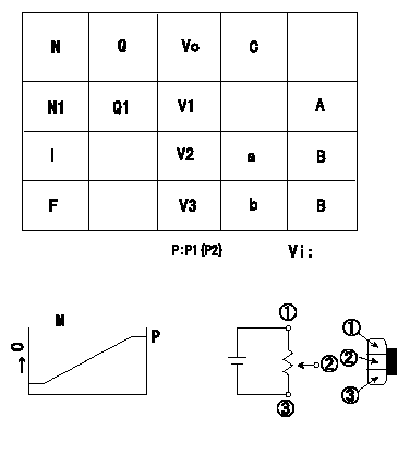
Adjustment of the potentiometer
Adjusting method (dummy bolt method):
1. Position the control lever at the adjusting points in the table, hold the dummy bolt against the lever and fix.
2. In the fixed position, install the potentiometer so that the output voltage is V1 (supply voltage Vi).
3. After completing potentiometer installation, remove the dummy bolt.
A:Adjusting point
B:Checking point
C:Control lever angle
N:Pump speed
Q:Injection quantity
Vo:Output voltage
M:Connecting diagram for the potentiometer
O:Output
P:Output when (2) and (3) connected.
I:Idle position
F:Full speed position
P:Boost pressure
----------
Vi=10V V1=3.4+-0.03V
----------
N1=600r/min V1=3.4+-0.03V V2=(1.3+-0.69)V V3=9.6--V Q1=16.9+-1.0cm3/1,000st a=0deg b=(42.5)deg Vi=10V
----------
Vi=10V V1=3.4+-0.03V
----------
N1=600r/min V1=3.4+-0.03V V2=(1.3+-0.69)V V3=9.6--V Q1=16.9+-1.0cm3/1,000st a=0deg b=(42.5)deg Vi=10V
0000001901 W-CSD ADJUSTMENT
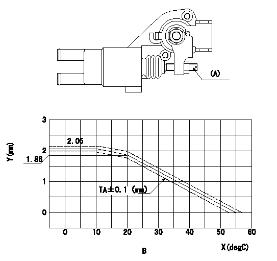
Adjustment of the W-CSD
Adjust the timer stroke determined from the graph below using screw (A).
X:Temperature t (deg C)
Y:Timer stroke TA
B:Timer stroke TA:
(O): diagram 1.
(P): diagram 2
----------
----------
B:t(degC)<=10:TA=2.05mm 10<=t(degC)<=20:TA=-0.019t+2.24 20<=t(degC)<=55:TA=-0.0531t+2.922
----------
----------
B:t(degC)<=10:TA=2.05mm 10<=t(degC)<=20:TA=-0.019t+2.24 20<=t(degC)<=55:TA=-0.0531t+2.922
0000002001 DASHPOT ADJUSTMENT
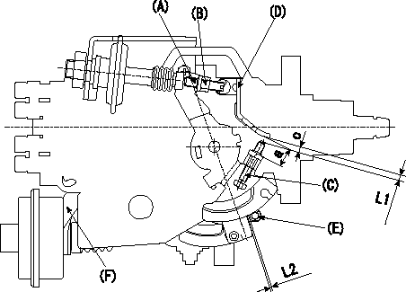
Adjustment of the dash pot
1. Insert a block gauge L1 (thickness gauge) between the idle set screw (C) and the control lever (D).
2. In the above condition, adjust the position of the dash pot so that the dash pot adjustment screw (A) contacts the push rod and then fix the screw using the nut (B).
TT
Note:
(1)The adjusting screw and pushrod contact faces must be smooth.
(2)Confirm that the control lever returns to the idling position.
ISC actuator installation
1. Maintain the control lever in the idling position.
2. Fix actuator bracket (F) so that the gap between the control lever and the ISC lever's roller (E) is L2.
----------
L1=2.7+-0.05mm L2=1.0-0.5+1.0mm T=6~9Nm{0.6~0.9kgfm}
----------
L1=2.7+-0.05mm L2=1.0-0.5+1.0mm
----------
L1=2.7+-0.05mm L2=1.0-0.5+1.0mm T=6~9Nm{0.6~0.9kgfm}
----------
L1=2.7+-0.05mm L2=1.0-0.5+1.0mm
Information:
If complete injector sets are replacedon 3412E machines:
PART Hours/Age, whichevercomes first Caterpillar Dealer Suggested Customer Suggested
Parts (D/N) Labor Hrs (Cost) Parts Labor Hrs Parts (C/L) Labor Hrs (Sell)
0-4000 0-48 mos 100% 7 0 0 0 0
4001-8000 0-48 mos 33.3% 3.5 0 0 50% 3.5
* This is a 7-hour job. Actual hourspermitted up to maximums noted above.PARTS DISPOSITION
NACD Dealers, return Injector(s) to:Caterpillar Inc.Attn: Fergal O?Shea ? PS50424
Service Claims Room
8201 N. University
Peoria, IL 61615 ***** All Other Dealers *****
Handle the parts in accordance with yourWarranty Bulletin on warranty parts handling.
Attach. (1-Rework Procedure)Rework Procedure
The two tests below provide the appropriateinjector troubleshooting and repair steps for injector updates.
Use "Test for Cylinder Cutout" to determine ifindividual injector replacements (using original injector part) are needed.
Use "Test for Leakage from Poppet Valve" to determineif full injector sets (using new injector parts and software change) areappropriate for repair.
Test for Cylinder Cutout:
Warm the engine out of Cold Mode.
Connect Caterpillar Electronic Technician (ET)to the engine while the engine is running.
Ensure that the engine speed is 1200 rpm +/- 125rpm. An extremely rough running engine well need to be diagnosed by othermethods.
Cut out one bank of cylinders. Note engine rpmand the fuel position on the ET screen at that time.
Cut out one of the remaining cylinders from thecylinder bank that is running. Allow the engine to stabilize and note thefuel position.
Give power back to that cylinder. Allow the engineto stabilize and note the fuel position.
Repeat steps 5 through 6 until the cylinder bankhas been completely checked.
Power all cylinders. Allow the engine to stabilize.
Cut out the other cylinder bank and repeat steps5 through 8.
Repeat steps 4 through 9 with the engine at 2000rpm.
Compare the results from the fuel position fromeach cylinder.
If the cylinder was cut out and the fuel positiondid not change, the cylinder may not have producing power. This cylinderwould be suspect.
When you are finished with the test, decreaseengine rpm to low idle and shut the engine off.
Replace any suspect injector with a similar originalinjector. Install new seals for the injector and the jumper tube duringthis repair. The injector repair procedure is found in Special InstructionREHS0116.
If this is the third injector failure,related to this Service Letter, and to the same engine serial number within120 calendar days, replace all the injectors and software following SpecialInstruction article REHS1385.It is also possible that multiple injectors arefunctioning improperly. Complete "Test for Leakage from Poppet Valve" inorder to evaluate potential excessive injector leakage and need for fuelsystem conversion.Test for Leakage from PoppetValve:
Warm engine out of Cold Mode to normal operatingtemperature.
Turn off the engine.
Remove the valve cover bolts in preparation toobserve the injectors. Leave covers in place.
: Hot oil and components can causepersonal injury. Do not allow hot oil or components to contact skin.
Restart the engine and run at low idle with noload.
Use the ET service tool in order to perform theoverride test for the injection actuation system. Increase injection actuationpressure to the maximum value.
Observe all of the injectors under each valvecover for leakage at the spill port. A small amount of dripping is acceptable.However, a continuous stream of oil is an indication of excessive leakageof the poppet valve. Only leaks at the spill port