Information injection-pump assembly
BOSCH
9 460 613 083
9460613083
ZEXEL
104760-2530
1047602530
Rating:
Components :
| 0. | INJECTION-PUMP ASSEMBLY | 104760-2530 |
| 1. | _ | |
| 2. | FUEL INJECTION PUMP | 104660-2510 |
| 3. | NUMBER PLATE | 146914-2400 |
| 4. | _ | |
| 5. | CAPSULE | |
| 6. | ADJUSTING DEVICE | 146679-0520 |
| 7. | NOZZLE AND HOLDER ASSY | 105141-2991 |
| 8. | Nozzle and Holder | 16600-84T07 |
| 9. | Open Pre:MPa(Kqf/cm2) | 12.7{130} |
| 10. | NOZZLE-HOLDER | 105071-0681 |
| 11. | NOZZLE | 105000-2200 |
Scheme ###:
| 1/6. | [1] | 146601-0700 | PACKING RING |
| 6. | [1] | 146100-0220 | SUPPLY PUMP |
| 9. | [1] | 146103-0100 | COVER |
| 10. | [2] | 139104-0000 | FLAT-HEAD SCREW |
| 12. | [1] | 146200-0420 | DRIVE SHAFT |
| 12/1. | [1] | 146200-0400 | DRIVE SHAFT |
| 12/2. | [1] | 146201-0000 | WOODRUFF KEY |
| 12/3. | [2] | 146202-0100 | DAMPER |
| 12/4. | [1] | 146203-0000 | TOOTHED GEAR |
| 17. | [1] | 146204-0000 | PLAIN WASHER |
| 20. | [1] | 146210-3420 | ROLLER SET |
| 24. | [1] | 146303-0000 | BEARING PIN |
| 25. | [1] | 146304-0000 | BEARING PIN |
| 26. | [1] | 146305-0000 | CLAMPING BAND |
| 27. | [1] | 146205-0000 | SLOTTED WASHER |
| 29. | [1] | 146221-1120 | CAM PLATE |
| 30. | [1] | 146600-0800 | O-RING |
| 31. | [1] | 146311-8620 | PUMP PLUNGER |
| 32. | [1] | 146301-0200 | SLIDING PIECE |
| 34. | [1] | 146312-3900 | COMPRESSION SPRING |
| 34B. | [1] | 146312-4000 | COMPRESSION SPRING |
| 35/1. | [1] | 146690-3200 | SHIM D11.5&9.4T0.1 |
| 35/1. | [1] | 146690-3300 | SHIM D11.5&9.4T0.2 |
| 35/1. | [1] | 146690-3400 | SHIM D11.5&9.4T0.25 |
| 35/1. | [1] | 146690-3500 | SHIM D11.5&9.4T1.0 |
| 35/1. | [1] | 146690-4100 | SHIM D11.5&9.4T2 |
| 35/1. | [1] | 146690-4200 | SHIM D11.5&9.4T0.5 |
| 35/1. | [1] | 146690-4300 | SHIM D11.5&9.4T0.75 |
| 36. | [1] | 146600-0800 | O-RING |
| 37. | [1] | 146310-1600 | COVER |
| 38. | [2] | 146620-5000 | BLEEDER SCREW |
| 39. | [1] | 146310-0100 | COVER |
| 40. | [2] | 146620-5000 | BLEEDER SCREW |
| 41. | [1] | 146312-4100 | COMPRESSION SPRING |
| 42. | [1] | 146602-8500 | PLAIN WASHER |
| 43. | [1] | 146230-0000 | SHIM |
| 44. | [1] | 146230-0100 | PLAIN WASHER |
| 45. | [1] | 146231-0001 | SLOTTED WASHER |
| 47. | [2] | 146233-0000 | SLOTTED WASHER |
| 48/1. | [1] | 146603-0000 | SHIM D17.0&5.2T0.50 |
| 48/1. | [1] | 146603-0100 | SHIM D17.0&5.2T0.80 |
| 48/1. | [1] | 146603-0200 | SHIM D17.0&5.2T1.00 |
| 48/1. | [1] | 146603-0300 | SHIM D17.0&5.2T1.20 |
| 48/1. | [1] | 146603-0400 | SHIM D17.0&5.2T1.50 |
| 48/1. | [1] | 146603-0500 | SHIM D17.0&5.2T1.80 |
| 48/1. | [1] | 146603-0600 | SHIM D17.0&5.2T2.00 |
| 48/1. | [1] | 146690-1400 | SHIM D17&5.2T0.9 |
| 48/1. | [1] | 146690-1500 | SHIM D17&5.2T1.1 |
| 48/1. | [1] | 146690-1600 | SHIM D17&5.2T1.3 |
| 48/1. | [1] | 146690-1700 | SHIM D17&5.2T1.4 |
| 48/1. | [1] | 146690-1800 | SHIM D17&5.2T1.6 |
| 48/1. | [1] | 146690-1900 | SHIM D17&5.2T1.7 |
| 48/1. | [1] | 146690-5800 | SHIM |
| 48/1. | [1] | 146690-5900 | SHIM |
| 48/1. | [1] | 146690-6000 | SHIM |
| 48/1. | [1] | 146690-6100 | SHIM |
| 48/1. | [1] | 146690-6200 | SHIM |
| 48/1. | [1] | 146690-6300 | SHIM |
| 48/1. | [1] | 146690-6400 | SHIM |
| 48/1. | [1] | 146690-6500 | SHIM |
| 48/1. | [1] | 146690-6600 | SHIM |
| 48/1. | [1] | 146690-6700 | SHIM |
| 48/1. | [1] | 146690-6800 | SHIM |
| 48/1. | [1] | 146690-6900 | SHIM |
| 48/1. | [1] | 146690-7000 | SHIM |
| 48/1. | [1] | 146690-7100 | SHIM |
| 48/1. | [1] | 146690-7200 | SHIM |
| 48/1. | [1] | 146690-7300 | SHIM |
| 48/1. | [1] | 146690-7400 | SHIM |
| 48/1. | [1] | 146690-7500 | SHIM |
| 48/1. | [1] | 146690-7800 | SHIM |
| 49. | [2] | 146234-0120 | GUIDE PIN |
| 50. | [1] | 146405-2720 | HYDRAULIC HEAD |
| 50. | [1] | 146405-2720 | HYDRAULIC HEAD |
| 50. | [1] | 146405-2720 | HYDRAULIC HEAD |
| 51. | [1] | 146600-0000 | O-RING |
| 52/1. | [1] | 146420-0000 | SHIM D9.5&3.0T1.90 |
| 52/1. | [1] | 146420-0100 | SHIM D9.5&3.0T1.92 |
| 52/1. | [1] | 146420-0200 | SHIM D9.5&3.0T1.94 |
| 52/1. | [1] | 146420-0300 | SHIM D9.5&3.0T1.96 |
| 52/1. | [1] | 146420-0400 | SHIM D9.5&3.0T1.98 |
| 52/1. | [1] | 146420-0500 | SHIM D9.5&3.0T2.00 |
| 52/1. | [1] | 146420-0600 | SHIM D9.5&3.0T2.02 |
| 52/1. | [1] | 146420-0700 | SHIM D9.5&3.0T2.04 |
| 52/1. | [1] | 146420-0800 | SHIM D9.5&3.0T2.06 |
| 52/1. | [1] | 146420-0900 | SHIM D9.5&3.0T2.08 |
| 52/1. | [1] | 146420-1000 | SHIM D9.5&3.0T2.10 |
| 52/1. | [1] | 146420-1100 | SHIM D9.5&3.0T2.12 |
| 52/1. | [1] | 146420-1200 | SHIM D9.5&3.0T2.14 |
| 52/1. | [1] | 146420-1300 | SHIM D9.5&3.0T2.16 |
| 52/1. | [1] | 146420-1400 | SHIM D9.5&3.0T2.18 |
| 52/1. | [1] | 146420-1500 | SHIM D9.5&3.0T2.20 |
| 52/1. | [1] | 146420-1600 | SHIM D9.5&3.0T2.22 |
| 52/1. | [1] | 146420-1700 | SHIM D9.5&3.0T2.24 |
| 52/1. | [1] | 146420-1800 | SHIM D9.5&3.0T2.26 |
| 52/1. | [1] | 146420-1900 | SHIM D9.5&3.0T2.28 |
| 52/1. | [1] | 146420-2000 | SHIM D9.5&3.0T2.30 |
| 52/1. | [1] | 146420-2100 | SHIM D9.5&3.0T2.32 |
| 52/1. | [1] | 146420-2200 | SHIM D9.5&3.0T2.34 |
| 52/1. | [1] | 146420-2300 | SHIM D9.5&3.0T2.36 |
| 52/1. | [1] | 146420-2400 | SHIM D9.5&3.0T2.38 |
| 52/1. | [1] | 146420-2500 | SHIM D9.5&3.0T2.40 |
| 52/1. | [1] | 146420-2600 | SHIM D9.5&3.0T2.42 |
| 52/1. | [1] | 146420-2700 | SHIM D9.5&3.0T2.44 |
| 52/1. | [1] | 146420-2800 | SHIM D9.5&3.0T2.46 |
| 52/1. | [1] | 146420-2900 | SHIM D9.5&3.0T2.48 |
| 52/1. | [1] | 146420-3000 | SHIM D9.5&3.0T2.50 |
| 52/1. | [1] | 146420-3100 | SHIM D9.5&3.0T2.52 |
| 52/1. | [1] | 146420-3200 | SHIM D9.5&3.0T2.54 |
| 52/1. | [1] | 146420-3300 | SHIM D9.5&3.0T2.56 |
| 52/1. | [1] | 146420-3400 | SHIM D9.5&3.0T2.58 |
| 52/1. | [1] | 146420-3500 | SHIM D9.5&3.0T2.60 |
| 52/1. | [1] | 146420-3600 | SHIM D9.5&3.0T2.62 |
| 52/1. | [1] | 146420-3700 | SHIM D9.5&3.0T2.64 |
| 52/1. | [1] | 146420-3800 | SHIM D9.5&3.0T2.66 |
| 52/1. | [1] | 146420-3900 | SHIM D9.5&3.0T2.68 |
| 52/1. | [1] | 146420-4000 | SHIM D9.5&3.0T2.70 |
| 52/1. | [1] | 146420-4100 | SHIM D9.5&3.0T2.72 |
| 52/1. | [1] | 146420-4200 | SHIM D9.5&3.0T2.74 |
| 52/1. | [1] | 146420-4300 | SHIM D9.5&3.0T2.76 |
| 52/1. | [1] | 146420-4400 | SHIM D9.5&3.0T2.78 |
| 52/1. | [1] | 146420-4500 | SHIM D9.5&3.0T2.80 |
| 52/1. | [1] | 146420-4600 | SHIM D9.5&3.0T2.82 |
| 52/1. | [1] | 146420-4700 | SHIM D9.5&3.0T2.84 |
| 52/1. | [1] | 146420-4800 | SHIM D9.5&3.0T2.86 |
| 52/1. | [1] | 146420-4900 | SHIM D9.5&3.0T2.88 |
| 52/1. | [1] | 146420-5000 | SHIM D9.5&3.0T2.90 |
| 52/1. | [1] | 146420-5100 | SHIM D9.5&3.0T1.74 |
| 52/1. | [1] | 146420-5200 | SHIM D9.5&3.0T1.76 |
| 52/1. | [1] | 146420-5300 | SHIM D9.5&3.0T1.78 |
| 52/1. | [1] | 146420-5400 | SHIM D9.5&3.0T1.80 |
| 52/1. | [1] | 146420-5500 | SHIM D9.5&3.0T1.82 |
| 52/1. | [1] | 146420-5600 | SHIM D9.5&3.0T1.84 |
| 52/1. | [1] | 146420-5700 | SHIM D9.5&3.0T1.86 |
| 52/1. | [1] | 146420-5800 | SHIM D9.5&3.0T1.88 |
| 54. | [6] | 146433-0100 | GASKET D12&6.4T1.00 |
| 55. | [6] | 146430-3220 | DELIVERY-VALVE ASSEMBLY |
| 56. | [6] | 146432-0000 | COMPRESSION SPRING |
| 58. | [6] | 146440-0220 | FITTING |
| 60. | [3] | 139106-0100 | FLAT-HEAD SCREW |
| 66. | [1] | 146600-0100 | O-RING |
| 67. | [1] | 146503-7320 | GOVERNOR COVER |
| 67/1. | [1] | 146805-7820 | GOVERNOR COVER |
| 67/14. | [1] | 146621-1700 | UNION NUT |
| 67/16. | [1] | 146526-3400 | BLEEDER SCREW |
| 67/78. | [1] | 146600-4400 | SEAL RING |
| 67/200. | [1] | 139308-0300 | PLAIN WASHER |
| 67/201. | [1] | 146545-3720 | THREADED PIN |
| 67/202. | [1] | 139208-0900 | UNION NUT |
| 67/203. | [1] | 146600-1200 | O-RING |
| 68. | [1] | 146514-4520 | CONTROL SHAFT |
| 69. | [1] | 139310-0200 | PLAIN WASHER |
| 72. | [1] | 146830-2520 | CONTROL LEVER |
| 72B. | [1] | 146830-2620 | CONTROL LEVER |
| 73. | [1] | 014110-6440 | LOCKING WASHER |
| 75. | [1] | 013020-6040 | UNION NUT M6P1H5 |
| 95. | [1] | 146565-9520 | FULCRUM LEVER |
| 104. | [2] | 146568-0000 | SLOTTED SPRING PIN |
| 105. | [2] | 026508-1140 | GASKET D11.4&8.2T1 |
| 106. | [2] | 146588-0500 | COILED SPRING |
| 107. | [1] | 146569-0300 | UNION NUT |
| 108. | [1] | 146570-0100 | GOVERNOR SHAFT |
| 109. | [1] | 146600-0400 | O-RING |
| 110/1. | [1] | 146571-0000 | SHIM D20.2&8.3T1.05 |
| 110/1. | [1] | 146571-0100 | SHIM D20.2&8.3T1.25 |
| 110/1. | [1] | 146571-0200 | SHIM D20.2&8.3T1.45 |
| 110/1. | [1] | 146571-0300 | SHIM D20.2&8.3T1.65 |
| 110/1. | [1] | 146571-0400 | SHIM D20.2&8.3T1.85 |
| 110/1. | [1] | 146571-0500 | SHIM D20.2&8.3T1.15 |
| 110/1. | [1] | 146571-0600 | SHIM D20.2&8.3T1.35 |
| 110/1. | [1] | 146571-0700 | SHIM D20.2&8.3T1.55 |
| 110/1. | [1] | 146571-0800 | SHIM D20.2&8.3T1.75 |
| 111. | [1] | 146602-0600 | PLAIN WASHER D20&8.4T1.40 |
| 112. | [1] | 146572-0020 | FLYWEIGHT ASSEMBLY |
| 114. | [1] | 146602-0500 | PLAIN WASHER D17&6.4T1.60 |
| 115. | [1] | 146575-2000 | SLIDING SLEEVE |
| 116. | [1] | 146576-0200 | CAP |
| 117/1. | [1] | 146577-1800 | PLUG L2.10 |
| 117/1. | [1] | 146577-1900 | PLUG L2.30 |
| 117/1. | [1] | 146577-2000 | PLUG L2.50 |
| 117/1. | [1] | 146577-2100 | PLUG L2.70 |
| 117/1. | [1] | 146577-2200 | PLUG L2.90 |
| 117/1. | [1] | 146577-2300 | PLUG L3.10 |
| 117/1. | [1] | 146577-2400 | PLUG L3.30 |
| 117/1. | [1] | 146577-2500 | PLUG L3.50 |
| 117/1. | [1] | 146577-2600 | PLUG L3.70 |
| 117/1. | [1] | 146577-2700 | PLUG L3.90 |
| 117/1. | [1] | 146577-2800 | PLUG L4.10 |
| 117/1. | [1] | 146577-2900 | PLUG L4.30 |
| 117/1. | [1] | 146577-3000 | PLUG L4.50 |
| 117/1. | [1] | 146577-3100 | PLUG L4.70 |
| 117/1. | [1] | 146577-3200 | PLUG L4.90 |
| 117/1. | [1] | 146577-3300 | PLUG L5.10 |
| 117/1. | [1] | 146577-6700 | PLUG L2.2 |
| 117/1. | [1] | 146577-6800 | PLUG L2.4 |
| 117/1. | [1] | 146577-6900 | PLUG L2.6 |
| 117/1. | [1] | 146577-7000 | PLUG L2.8 |
| 117/1. | [1] | 146577-7100 | PLUG L3.0 |
| 117/1. | [1] | 146577-7200 | PLUG L3.2 |
| 117/1. | [1] | 146577-7300 | PLUG L3.4 |
| 117/1. | [1] | 146577-7400 | PLUG L3.6 |
| 117/1. | [1] | 146577-7500 | PLUG L3.8 |
| 117/1. | [1] | 146577-7600 | PLUG L4.0 |
| 117/1. | [1] | 146577-7700 | PLUG L4.2 |
| 117/1. | [1] | 146577-7800 | PLUG L4.4 |
| 117/1. | [1] | 146577-7900 | PLUG L4.6 |
| 117/1. | [1] | 146577-8000 | PLUG L4.8 |
| 117/1. | [1] | 146577-8100 | PLUG L5.0 |
| 117/1. | [1] | 146877-0000 | PLUG L5.2 |
| 117/1. | [1] | 146877-0100 | PLUG L5.3 |
| 117/1. | [1] | 146877-0200 | PLUG L5.4 |
| 117/1. | [1] | 146877-0300 | PLUG L5.5 |
| 117/1. | [1] | 146877-4700 | PLUG |
| 117/1. | [1] | 146877-4800 | PLUG |
| 117/1. | [1] | 146877-4900 | PLUG |
| 117/1. | [1] | 146877-5000 | PLUG |
| 123. | [4] | 139106-0200 | FLAT-HEAD SCREW |
| 123. | [4] | 139106-0200 | FLAT-HEAD SCREW |
| 130. | [1] | 146421-0020 | CAPSULE |
| 130/2. | [1] | 026508-1140 | GASKET D11.4&8.2T1 |
| 130/3. | [1] | 146422-0000 | BLEEDER SCREW |
| 130/4. | [1] | 146600-0500 | O-RING |
| 133. | [1] | 146600-0600 | O-RING |
| 134. | [1] | 146600-0700 | O-RING |
| 135. | [1] | 146110-0220 | CONTROL VALVE |
| 135/5. | [1] | 146114-0000 | SPRING WASHER |
| 136. | [1] | 146650-6020 | PULLING ELECTROMAGNET |
| 136B. | [1] | 146650-5420 | PULLING ELECTROMAGNET |
| 136C. | [1] | 146650-6320 | PULLING ELECTROMAGNET |
| 137. | [2] | 139514-0200 | GASKET |
| 145. | [1] | 146621-1000 | UNION NUT |
| 147. | [1] | 016520-1210 | O-RING |
| 200. | [1] | 146206-0100 | COILED SPRING |
| 214. | [1] | 146542-5000 | BUSHING |
| 216. | [1] | 146542-5100 | BUSHING |
| 217. | [1] | 146541-3100 | SLOTTED WASHER |
| 218. | [1] | 146592-5600 | COILED SPRING |
| 219. | [1] | 146541-3000 | BUSHING |
| 220. | [1] | 146592-5700 | COILED SPRING |
| 221. | [1] | 146927-3720 | BRACKET |
| 222. | [2] | 139006-4600 | BLEEDER SCREW |
| 224. | [1] | 146925-0300 | BRACKET |
| 231. | [1] | 020146-1440 | BLEEDER SCREW M6P1L14 |
| 234. | [2] | 020146-1270 | BLEEDER SCREW |
| 236. | [2] | 139006-4800 | BLEEDER SCREW |
| 236. | [2] | 139006-4800 | BLEEDER SCREW |
| 237. | [1] | 146620-0200 | HEX-SOCKET-HEAD CAP SCREW |
| 237. | [1] | 146620-0200 | HEX-SOCKET-HEAD CAP SCREW |
| 240. | [1] | 146650-0720 | PULLING ELECTROMAGNET |
| 240/8. | [1] | 146600-1700 | O-RING |
| 243. | [1] | 146621-1000 | UNION NUT |
| 245. | [3] | 139512-0200 | GASKET D18.5&12.2T1.00 |
| 246. | [1] | 139812-0500 | EYE BOLT |
| 247. | [1] | 146666-0420 | PIPE |
| 248. | [1] | 146614-0200 | SPACER BUSHING |
| 275. | [1] | 146612-5620 | BRACKET |
| 276. | [2] | 010010-1640 | BLEEDER SCREW M10P1.5L16 4T |
| 280. | [1] | 146361-1020 | START ADVANCE ASSY |
| 281. | [1] | 146600-0800 | O-RING |
| 282. | [2] | 010206-1240 | HEX-SOCKET-HEAD CAP SCREW M6P1L12 |
| 287. | [2] | 020146-1440 | BLEEDER SCREW M6P1L14 |
| 309. | [1] | 020146-1440 | BLEEDER SCREW M6P1L14 |
| 311. | [2] | 010206-1040 | HEX-SOCKET-HEAD CAP SCREW |
| 318. | [1] | 146930-4820 | BRACKET |
| 320. | [1] | 020146-2040 | BLEEDER SCREW M6P1.0L20 4T |
| 330. | [1] | 146927-0600 | PLATE |
| 331. | [2] | 020106-1040 | BLEEDER SCREW M6P1L12 |
| 350. | [1] | 146930-6820 | BRACKET |
| 455. | [1] | 146547-8720 | RACK |
| 800S. | [1] | 146019-3520 | PUMP HOUSING |
| 800S/1/6. | [1] | 146601-0700 | PACKING RING |
| 804S. | [1] | 146232-0720 | COMPRESSION SPRING |
| 805S. | [1] | 146574-0120 | PARTS SET |
| 810S. | [1] | 146600-1120 | REPAIR SET |
| 835S. | [1] | 146598-1000 | CAP |
| 836S/1. | [1] | 146598-0600 | CAP L18 |
| 836S/1. | [1] | 146598-0700 | CAP L21 |
| 836S/1. | [1] | 146598-0800 | CAP L24 |
| 836S/1. | [1] | 146598-0900 | CAP L27 |
| 905. | [1] | 146679-0520 | ACTUATOR |
| 905/2. | [1] | 146627-4901 | BRACKET |
| 905/3. | [2] | 020146-1270 | BLEEDER SCREW |
| 906. | [1] | 146914-2400 | NAMEPLATE |
| 916. | [1] | 146662-2520 | WIRE |
| 924. | [1] | 146680-5320 | DAMPER |
| 925. | [2] | 020146-2040 | BLEEDER SCREW M6P1.0L20 4T |
| 936. | [1] | 146684-0120 | POTENTCIOMETER |
| 936/2. | [1] | 146930-6600 | BRACKET |
| 936/3. | [2] | 139104-0400 | FLAT-HEAD SCREW |
| 936/4. | [1] | 146649-0400 | JOINT CONNECTION |
| 936/4B. | [1] | 146649-0500 | JOINT CONNECTION |
| 936/4C. | [1] | 146649-0600 | JOINT CONNECTION |
| 936/4D. | [1] | 146649-0700 | JOINT CONNECTION |
| 936/4E. | [1] | 146649-0800 | JOINT CONNECTION |
| 936/4F. | [1] | 146649-0900 | JOINT CONNECTION |
| 936/4G. | [1] | 146649-1000 | JOINT CONNECTION |
| 936/4H. | [1] | 146649-1100 | JOINT CONNECTION |
| 936/4I. | [1] | 146649-1200 | JOINT CONNECTION |
| 936/4J. | [1] | 146649-1300 | JOINT CONNECTION |
| 936/4K. | [1] | 146649-1400 | JOINT CONNECTION |
| 936/4L. | [1] | 146649-1500 | JOINT CONNECTION |
| 937. | [1] | 146927-4000 | BRACKET |
Include in #2:
104760-2530
as INJECTION-PUMP ASSEMBLY
Cross reference number
BOSCH
9 460 613 083
9460613083
ZEXEL
104760-2530
1047602530
Zexel num
Bosch num
Firm num
Name
Calibration Data:
Adjustment conditions
Test oil
1404 Test oil ISO4113orSAEJ967d
1404 Test oil ISO4113orSAEJ967d
Test oil temperature
degC
45
45
50
Nozzle
105780-0060
Bosch type code
NP-DN0SD1510
Nozzle holder
105780-2150
Opening pressure
MPa
13
13
13.3
Opening pressure
kgf/cm2
133
133
136
Injection pipe
157805-7320
Injection pipe
Inside diameter - outside diameter - length (mm) mm 2-6-450
Inside diameter - outside diameter - length (mm) mm 2-6-450
Joint assembly
157641-4720
Tube assembly
157641-4020
Transfer pump pressure
kPa
20
20
20
Transfer pump pressure
kgf/cm2
0.2
0.2
0.2
Direction of rotation (viewed from drive side)
Right R
Right R
(Solenoid timer adjustment condition)
ON ON
ON ON
Injection timing adjustment
Pump speed
r/min
700
700
700
Average injection quantity
mm3/st.
31
30.6
31.4
Difference in delivery
mm3/st.
2
Basic
*
Oil temperature
degC
50
48
52
Injection timing adjustment_02
Pump speed
r/min
600
600
600
Average injection quantity
mm3/st.
31
29
33
Oil temperature
degC
50
48
52
Injection timing adjustment_03
Pump speed
r/min
700
700
700
Average injection quantity
mm3/st.
31
30
32
Difference in delivery
mm3/st.
2.5
Basic
*
Oil temperature
degC
50
48
52
Injection timing adjustment_04
Pump speed
r/min
1200
1200
1200
Average injection quantity
mm3/st.
33.2
30.7
35.7
Oil temperature
degC
50
48
52
Injection timing adjustment_05
Pump speed
r/min
1800
1800
1800
Average injection quantity
mm3/st.
32.4
29.9
34.9
Oil temperature
degC
50
48
52
Injection timing adjustment_06
Pump speed
r/min
2300
2300
2300
Average injection quantity
mm3/st.
33.4
30.4
36.4
Oil temperature
degC
52
50
54
Injection timing adjustment_07
Pump speed
r/min
2500
2500
2500
Average injection quantity
mm3/st.
33.5
30
37
Oil temperature
degC
55
52
58
Injection quantity adjustment
Pump speed
r/min
2600
2600
2600
Average injection quantity
mm3/st.
27
25
29
Difference in delivery
mm3/st.
4.5
Basic
*
Oil temperature
degC
55
52
58
Injection quantity adjustment_02
Pump speed
r/min
2600
2600
2600
Average injection quantity
mm3/st.
27
23.5
30.5
Difference in delivery
mm3/st.
5
Basic
*
Oil temperature
degC
55
52
58
Injection quantity adjustment_03
Pump speed
r/min
2800
2800
2800
Average injection quantity
mm3/st.
6.5
Oil temperature
degC
55
52
58
Governor adjustment
Pump speed
r/min
290
290
290
Average injection quantity
mm3/st.
9
8
10
Difference in delivery
mm3/st.
1.1
Basic
*
Oil temperature
degC
48
46
50
Governor adjustment_02
Pump speed
r/min
290
290
290
Average injection quantity
mm3/st.
9
7
11
Difference in delivery
mm3/st.
1.8
Basic
*
Oil temperature
degC
48
46
50
Timer adjustment
Pump speed
r/min
100
100
100
Average injection quantity
mm3/st.
40
40
Basic
*
Oil temperature
degC
48
46
50
Remarks
Full
Full
Timer adjustment_02
Pump speed
r/min
100
100
100
Average injection quantity
mm3/st.
40
40
Oil temperature
degC
48
46
50
Speed control lever angle
Pump speed
r/min
900
900
900
Average injection quantity
mm3/st.
0
0
0
Oil temperature
degC
50
48
52
Remarks
Magnet OFF at full-load position
Magnet OFF at full-load position
Speed control lever angle_02
Pump speed
r/min
290
290
290
Average injection quantity
mm3/st.
4
Oil temperature
degC
48
46
50
Remarks
Magnet OFF at idling position
Magnet OFF at idling position
0000000901
Pump speed
r/min
900
900
900
Overflow quantity with S/T ON
cm3/min
390
260
520
Oil temperature
degC
50
48
52
Stop lever angle
Pump speed
r/min
900
900
900
Pressure with S/T ON
kPa
373
344
402
Pressure with S/T ON
kgf/cm2
3.8
3.5
4.1
Pressure with S/T OFF
kPa
314
265
363
Pressure with S/T OFF
kgf/cm2
3.2
2.7
3.7
Basic
*
Oil temperature
degC
50
48
52
Remarks
ON
ON
Stop lever angle_02
Pump speed
r/min
900
900
900
Pressure
kPa
372.5
333
412
Pressure
kgf/cm2
3.8
3.4
4.2
Basic
*
Oil temperature
degC
50
48
52
Stop lever angle_03
Pump speed
r/min
1800
1800
1800
Pressure
kPa
578.5
539
618
Pressure
kgf/cm2
5.9
5.5
6.3
Oil temperature
degC
50
48
52
Stop lever angle_04
Pump speed
r/min
2500
2500
2500
Pressure
kPa
745.5
706
785
Pressure
kgf/cm2
7.6
7.2
8
Oil temperature
degC
55
52
58
0000001101
Pump speed
r/min
900
900
900
Timer stroke with S/T ON
mm
4.6
4.4
4.8
Timer stroke with S/T OFF
mm
2.9
2.5
3.3
Basic
*
Oil temperature
degC
50
48
52
Remarks
ON
ON
_02
Pump speed
r/min
900
900
900
Timer stroke with S/T ON
mm
4.6
4.3
4.9
Timer stroke with S/T OFF
mm
2.9
2.4
3.4
Basic
*
Oil temperature
degC
50
48
52
_03
Pump speed
r/min
1200
1200
1200
Timer stroke with S/T ON
mm
6.1
5.6
6.6
Oil temperature
degC
50
48
52
_04
Pump speed
r/min
1800
1800
1800
Timer stroke with S/T ON
mm
9.1
8.4
9.8
Oil temperature
degC
50
48
52
_05
Pump speed
r/min
2300
2300
2300
Timer stroke with S/T ON
mm
11.05
10.6
11.5
Oil temperature
degC
52
50
54
0000001201
Max. applied voltage
V
8
8
8
Test voltage
V
13
12
14
Timing setting
K dimension
mm
3.3
3.2
3.4
KF dimension
mm
7.22
7.12
7.32
MS dimension
mm
1.8
1.7
1.9
Control lever angle alpha
deg.
23
19
27
Control lever angle beta
deg.
42.5
37.5
47.5
Test data Ex:
0000001801 POTENTIOMETER ADJUSTMENT
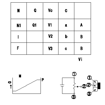
Adjustment of the potentiometer
Adjusting method (dummy bolt method)
1. Position the control lever at the adjusting points in the table, hold the dummy bolt against the lever and fix.
2. In the fixed position, install the potentiometer so that the output voltage is V1 (supply voltage Vi).
3. After completing potentiometer installation, remove the dummy bolt.
A:Standard point
B:Checking point
C:Control lever angle
I:Idle position
F:Full speed position
N:Pump speed
Q:Injection quantity
Vo:Output voltage
M:Connecting diagram for the potentiometer
O:Output
P:Output when (2) and (3) connected.
----------
V1=3.2+-0.03(V) Vi=10(V)
----------
N1=600(r/min) Q1=16.9+-1.0(mm3/st) V1=3.2+-0.03(V) V2=0.5++(V) V3=9.6--(V) a=(10.8(deg)) b=0(deg) c=(42.5(deg)) Vi=10(V)
----------
V1=3.2+-0.03(V) Vi=10(V)
----------
N1=600(r/min) Q1=16.9+-1.0(mm3/st) V1=3.2+-0.03(V) V2=0.5++(V) V3=9.6--(V) a=(10.8(deg)) b=0(deg) c=(42.5(deg)) Vi=10(V)
0000001901 W-CSD ADJUSTMENT
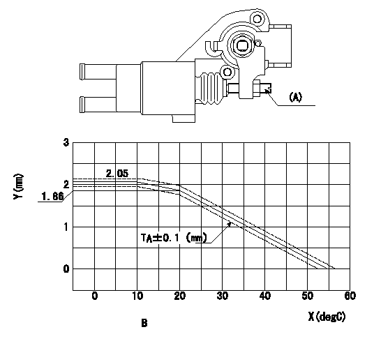
Adjustment of the W-CSD
Adjust screw (A) so that the timer stroke is as determined from the graph and the formula.
Formula t (deg C) <= 10 TA = 2.05
10<= t (deg C) <= 20 TA = -0.019t+2.24
20 < t (deg C) <= 55 TA = -0.0531t + 2.922
X:Temperature t (deg C)
Y:Timer stroke TA
B:Timer stroke graph
----------
----------
----------
----------
0000002001 DASHPOT ADJUSTMENT
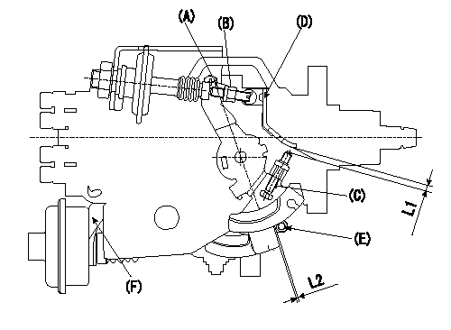
(1)Adjustment of the dash pot
1. Insert a block gauge L1 between the idle set screw (C) and the bracket (D).
2. In the above condition, adjust the locknut (B) so that the dashpot adjusting (A) contacts the pushrod, and then fix the locknut (Tightening torque T).
3.The dashpot and control lever contact faces must be smooth. Confirm that the control lever returns to the idle position.
(2)ISC actuator installation
In the idle position, fix the actuator bracket (F) so that the clearance between the control lever and the ISC lever roller (E) is L2.
----------
L1=2.7+-0.05(mm) L2=1.0+1.0-0.5(mm) T=6~9(N-m)(0.6~0.9(kgf-m))
----------
L1=2.7+-0.05(mm) L2=1.0+1.0-0.5(mm)
----------
L1=2.7+-0.05(mm) L2=1.0+1.0-0.5(mm) T=6~9(N-m)(0.6~0.9(kgf-m))
----------
L1=2.7+-0.05(mm) L2=1.0+1.0-0.5(mm)
Information:
Start By:a. remove rocker shaft assembly and push rodsb. remove exhaust manifoldc. remove air cleaner groupd. remove aftercooler The procedure which follows was done on a 3306 Engine. 1. Remove bolts (1), mounting bracket and pipe assembly (2) and lifting bracket (3) from the cylinder head assembly. 2. Remove temperature sending unit (5) from elbow (4).3. Loosen clamp (6), and remove the bolts that hold elbow (4) to the water pump and cylinder head assembly. Remove the elbow and gaskets from the engine. 4. Install Tool (A) on the cylinder head assembly as shown, and fasten a hoist on it.
Do not set the cylinder head assembly on a flat surface because of possible damage to the fuel injection nozzle tips.
5. Remove all bolts (7) and (8) that hold the cylinder head assembly to the cylinder block. Remove the cylinder head assembly. The weight of the cylinder head assembly (3304) is 64 kg (142 lb). The weight of the cylinder head assembly (3306) is 95 kg (210 lb). 6. Remove head gasket (9), water seals (11) and the O-ring seal from dowel (10). Remove spacer plate (12), the spacer plate gasket and the O-ring seal from dowel (10).Install Cylinder Head Assembly & Spacer Plate
The procedure which follows was done on a 3306 Engine.
When the cylinder head assembly is removed a new spacer plate gasket and a new cylinder head gasket must be installed. Do not use any adhesive or other substances on these gaskets or the surfaces they contact.
1. Thoroughly clean the spacer plate, cylinder head and cylinder block surfaces. If dowel (1) was removed for any reason, install a new dowel until it extends 16.0 0.5 mm (.63 .02 in) from the cylinder block.2. Install the O-ring seal on dowel (1) against the cylinder block. Install spacer plate gasket (2) and spacer plate (3) on the cylinder block.3. Check the cylinder liner projection height. See topic, "Install Cylinder Liners". 4. Install the O-ring seal on top of the spacer plate around dowel (1). Install cylinder head gasket (4) and water seals (5). 5. Install Tool (A) on the cylinder head assembly as shown. Fasten a hoist to it. Put the cylinder head assembly in position on the engine.6. Put 2P2506 Thread Lubricant on all the cylinder head bolts. Install them until they are finger tight. Remove Tool (A) from the engine. 7. Install push rods (6). Make sure they are installed in their original locations. Be sure the push rods are in position in the valve lifters.8. Loosen the adjusting screws on the rocker arms for valve clearance. This will prevent a bend valve or push rod during installation of the rocker shaft assembly.9. Install a new O-ring seal in the rear rocker arm support bracket.10. Put 2P2506 Thread Lubricant on all of the rocker shaft bolts except the one that goes through the rear rocker arm support bracket.11. Put rocker shaft assembly (7) in position on the cylinder head assembly. Make sure the dowels in