Information injection-pump assembly
ZEXEL
104760-2492
1047602492
Rating:
Cross reference number
ZEXEL
104760-2492
1047602492
Zexel num
Bosch num
Firm num
Name
104760-2492
INJECTION-PUMP ASSEMBLY
Calibration Data:
Adjustment conditions
Test oil
1404 Test oil ISO4113orSAEJ967d
1404 Test oil ISO4113orSAEJ967d
Test oil temperature
degC
45
45
50
Nozzle
105780-0060
Bosch type code
NP-DN0SD1510
Nozzle holder
105780-2150
Opening pressure
MPa
13
13
13.3
Opening pressure
kgf/cm2
133
133
136
Injection pipe
157805-7320
Injection pipe
Inside diameter - outside diameter - length (mm) mm 2-6-450
Inside diameter - outside diameter - length (mm) mm 2-6-450
Joint assembly
157641-4720
Tube assembly
157641-4020
Transfer pump pressure
kPa
20
20
20
Transfer pump pressure
kgf/cm2
0.2
0.2
0.2
Direction of rotation (viewed from drive side)
Right R
Right R
Injection timing adjustment
Pump speed
r/min
900
900
900
Average injection quantity
mm3/st.
30.5
30
31
Difference in delivery
mm3/st.
2
Basic
*
Injection timing adjustment_02
Pump speed
r/min
2600
2600
2600
Average injection quantity
mm3/st.
27
24.5
29.5
Injection timing adjustment_03
Pump speed
r/min
2500
2500
2500
Average injection quantity
mm3/st.
30.7
28.6
32.8
Injection timing adjustment_04
Pump speed
r/min
2300
2300
2300
Average injection quantity
mm3/st.
30.2
28.2
32.2
Injection timing adjustment_05
Pump speed
r/min
1800
1800
1800
Average injection quantity
mm3/st.
30.6
28.6
32.6
Injection timing adjustment_06
Pump speed
r/min
1200
1200
1200
Average injection quantity
mm3/st.
30.9
29.4
32.4
Injection timing adjustment_07
Pump speed
r/min
900
900
900
Average injection quantity
mm3/st.
30.5
29.5
31.5
Injection timing adjustment_08
Pump speed
r/min
600
600
600
Average injection quantity
mm3/st.
31.3
29.5
33.1
Injection quantity adjustment
Pump speed
r/min
2600
2600
2600
Average injection quantity
mm3/st.
27
25
29
Difference in delivery
mm3/st.
4.5
Basic
*
Injection quantity adjustment_02
Pump speed
r/min
2800
2800
2800
Average injection quantity
mm3/st.
6.5
Governor adjustment
Pump speed
r/min
290
290
290
Average injection quantity
mm3/st.
9
8
10
Difference in delivery
mm3/st.
1.1
Basic
*
Governor adjustment_02
Pump speed
r/min
500
500
500
Average injection quantity
mm3/st.
3
Governor adjustment_03
Pump speed
r/min
290
290
290
Average injection quantity
mm3/st.
9
7.5
10.5
Boost compensator adjustment
Pump speed
r/min
600
600
600
Average injection quantity
mm3/st.
16.9
10.4
23.4
Timer adjustment
Pump speed
r/min
100
100
100
Average injection quantity
mm3/st.
40
40
Difference in delivery
mm3/st.
15
Basic
*
Speed control lever angle
Pump speed
r/min
900
900
900
Average injection quantity
mm3/st.
0
0
0
Remarks
Magnet OFF at full-load position
Magnet OFF at full-load position
Speed control lever angle_02
Pump speed
r/min
290
290
290
Average injection quantity
mm3/st.
4
Remarks
Magnet OFF at idling position
Magnet OFF at idling position
0000000901
Pump speed
r/min
900
900
900
Overflow quantity
cm3/min
390
258
522
Stop lever angle
Pump speed
r/min
900
900
900
Pressure
kPa
372.5
343
402
Pressure
kgf/cm2
3.8
3.5
4.1
Basic
*
Stop lever angle_02
Pump speed
r/min
900
900
900
Pressure
kPa
372.5
343
402
Pressure
kgf/cm2
3.8
3.5
4.1
Stop lever angle_03
Pump speed
r/min
1800
1800
1800
Pressure
kPa
578.5
549
608
Pressure
kgf/cm2
5.9
5.6
6.2
Stop lever angle_04
Pump speed
r/min
2500
2500
2500
Pressure
kPa
745.5
716
775
Pressure
kgf/cm2
7.6
7.3
7.9
0000001101
Pump speed
r/min
900
900
900
Timer stroke
mm
2.3
2.1
2.5
Basic
*
_02
Pump speed
r/min
900
900
900
Timer stroke
mm
2.3
2
2.6
_03
Pump speed
r/min
1200
1200
1200
Timer stroke
mm
3.8
3.2
4.4
_04
Pump speed
r/min
1800
1800
1800
Timer stroke
mm
7
6.2
7.8
_05
Pump speed
r/min
2300
2300
2300
Timer stroke
mm
8.9
8.4
9.4
0000001201
Max. applied voltage
V
8
8
8
Test voltage
V
13
12
14
Timing setting
K dimension
mm
3.3
3.2
3.4
KF dimension
mm
7.24
7.14
7.34
MS dimension
mm
1.8
1.7
1.9
Control lever angle alpha
deg.
23
19
27
Control lever angle beta
deg.
42
37
47
Control lever angle gamma
deg.
14.4
13.9
14.9
Test data Ex:
0000001801 POTENTIOMETER ADJUSTMENT
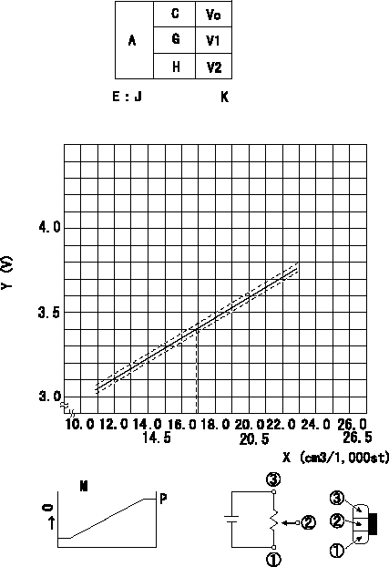
Adjustment of the potentiometer
In the following condition, change the installation position of the potentiometer to adjust the output voltage to within the specified values.
At N = N1 and control lever position a (corresponding to shim thickness L), measure the injection quantity, calculate the voltage from the graph, and then adjust the potentiometer.
A:Performance standards
C:Position of the control lever
N:Pump speed
Vo:Output voltage
E:Conversion formula (J)
G:Idle
H:Full speed
K:Applied voltage
X:Injection quantity (mm3/st)
Y:Voltage (V)
M:Connecting diagram for the potentiometer
O:Output
P:Output when (2) and (3) connected.
----------
N1=600r/min a=14.4deg L=7.7mm
----------
V1=1.00+-0.6V V2=7.80+-1.4V J=V+-0.03=0.0592X+-2.394 K=10V
----------
N1=600r/min a=14.4deg L=7.7mm
----------
V1=1.00+-0.6V V2=7.80+-1.4V J=V+-0.03=0.0592X+-2.394 K=10V
0000001901 W-CSD ADJUSTMENT
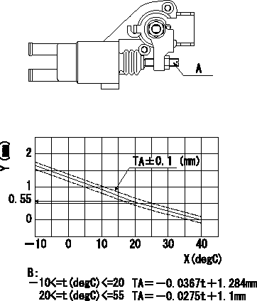
Adjustment of the W-CSD
Adjust the timer stroke using the screw so that it is as determined from the graph.
Caution: The temperature of the wax at adjustment must not exceed a.
A:Screw
B:Timer stroke graph
X:Temperature t
Y:Timer stroke TA
----------
a=30degC
----------
----------
a=30degC
----------
0000002001 DASHPOT ADJUSTMENT
Adjustment of the dash pot
1. Insert a block gauge L1 (thickness gauge) between the idle set screw (C) and the control lever (D).
2. In the above condition, adjust the position of the dash pot so that the dash pot adjustment screw (A) contacts the push rod and then fix the screw using the nut (B).
TT
Note:
(1)The adjusting screw and pushrod contact faces must be smooth.
(2)Confirm that the control lever returns to the idling position.
ISC actuator installation
1. Maintain the control lever in the idling position.
2. Fix actuator bracket (F) so that the gap between the control lever and the ISC lever's roller (E) is L2.
----------
L1=1.8+-0.05mm L2=1.0-0.5+1.0mm T=6~9Nm{0.6~0.9kgfm}
----------
L1=1.8+-0.05mm L2=1.0-0.5+1.0mm
----------
L1=1.8+-0.05mm L2=1.0-0.5+1.0mm T=6~9Nm{0.6~0.9kgfm}
----------
L1=1.8+-0.05mm L2=1.0-0.5+1.0mm
Information:
Termination Date
October 31, 1993Problem
Certain 2S7264 and 3S1467 Fuel Injection Pump Assemblies need to be removed from parts stock.
Action Required
Remove all 2S7264 and 3S1467 Fuel Injection Pump Assemblies from parts stock with date codes of December 1992 through March 1993. The date code appears at the bottom of the part number label on the pump box. The first two numbers indicate the month and the next two numbers indicate the year as shown in the example below:
Service Claim Allowances
Submit one claim for all 2S7264 and 3S1467 Fuel Injection Pump Assemblies removed from parts stock.
US and Canadian Dealers Only - When submitting a parts stock claim use 99Z00007 in the Product Identification Number Field.
Parts Disposition
U.S. And Canadian Dealers
Return all 2S7264 and 3S1467 Fuel Injection Pump Assemblies that are removed from parts stock and a copy of the claim to:
Caterpillar Inc.
Memory Lane
B Receiving
York, PA 17402
Attention: Quality Dept./PI7318
All Other Dealers
Handle the parts in accordance with your Warranty Bulletin on warranty parts handling.
Have questions with 104760-2492?
Group cross 104760-2492 ZEXEL
Nissan
104760-2492
INJECTION-PUMP ASSEMBLY