Information injection-pump assembly
ZEXEL
104760-2410
1047602410
Rating:
Cross reference number
ZEXEL
104760-2410
1047602410
Zexel num
Bosch num
Firm num
Name
Calibration Data:
Adjustment conditions
Test oil
1404 Test oil ISO4113orSAEJ967d
1404 Test oil ISO4113orSAEJ967d
Test oil temperature
degC
45
45
50
Nozzle
105780-0060
Bosch type code
NP-DN0SD1510
Nozzle holder
105780-2150
Opening pressure
MPa
13
13
13.3
Opening pressure
kgf/cm2
133
133
136
Injection pipe
157805-7320
Injection pipe
Inside diameter - outside diameter - length (mm) mm 2-6-450
Inside diameter - outside diameter - length (mm) mm 2-6-450
Joint assembly
157641-4720
Tube assembly
157641-4020
Transfer pump pressure
kPa
20
20
20
Transfer pump pressure
kgf/cm2
0.2
0.2
0.2
Direction of rotation (viewed from drive side)
Right R
Right R
Injection timing adjustment
Pump speed
r/min
900
900
900
Average injection quantity
mm3/st.
30.5
30.1
30.9
Difference in delivery
mm3/st.
2
Basic
*
Injection timing adjustment_02
Pump speed
r/min
2600
2600
2600
Average injection quantity
mm3/st.
27
24.5
29.5
Injection timing adjustment_03
Pump speed
r/min
2500
2500
2500
Average injection quantity
mm3/st.
30.7
28.6
32.8
Injection timing adjustment_04
Pump speed
r/min
2300
2300
2300
Average injection quantity
mm3/st.
30.2
28.2
32.2
Injection timing adjustment_05
Pump speed
r/min
1800
1800
1800
Average injection quantity
mm3/st.
30.6
28.6
32.6
Injection timing adjustment_06
Pump speed
r/min
1200
1200
1200
Average injection quantity
mm3/st.
30.9
29.4
32.4
Injection timing adjustment_07
Pump speed
r/min
900
900
900
Average injection quantity
mm3/st.
30.5
29.6
31.4
Injection timing adjustment_08
Pump speed
r/min
600
600
600
Average injection quantity
mm3/st.
31.3
29.5
33.1
Injection quantity adjustment
Pump speed
r/min
2600
2600
2600
Average injection quantity
mm3/st.
27
25
29
Difference in delivery
mm3/st.
4.5
Basic
*
Injection quantity adjustment_02
Pump speed
r/min
2800
2800
2800
Average injection quantity
mm3/st.
6.5
Governor adjustment
Pump speed
r/min
290
290
290
Average injection quantity
mm3/st.
9
8
10
Difference in delivery
mm3/st.
1.1
Basic
*
Governor adjustment_02
Pump speed
r/min
290
290
290
Average injection quantity
mm3/st.
9
8
10
Governor adjustment_03
Pump speed
r/min
500
500
500
Average injection quantity
mm3/st.
3
Boost compensator adjustment
Pump speed
r/min
900
900
900
Average injection quantity
mm3/st.
11.8
5.3
18.3
Remarks
From idle
From idle
Timer adjustment
Pump speed
r/min
100
100
100
Average injection quantity
mm3/st.
40
40
Difference in delivery
mm3/st.
15
Basic
*
Speed control lever angle
Pump speed
r/min
290
290
290
Average injection quantity
mm3/st.
4
Remarks
Magnet OFF
Magnet OFF
Speed control lever angle_02
Pump speed
r/min
900
900
900
Average injection quantity
mm3/st.
0
0
0
Remarks
Magnet OFF
Magnet OFF
0000000901
Pump speed
r/min
900
900
900
Overflow quantity
cm3/min
390
258
522
Stop lever angle
Pump speed
r/min
900
900
900
Pressure
kPa
372.5
343
402
Pressure
kgf/cm2
3.8
3.5
4.1
Basic
*
Stop lever angle_02
Pump speed
r/min
900
900
900
Pressure
kPa
372.5
343
402
Pressure
kgf/cm2
3.8
3.5
4.1
Stop lever angle_03
Pump speed
r/min
1800
1800
1800
Pressure
kPa
578.5
549
608
Pressure
kgf/cm2
5.9
5.6
6.2
Stop lever angle_04
Pump speed
r/min
2500
2500
2500
Pressure
kPa
745.5
716
775
Pressure
kgf/cm2
7.6
7.3
7.9
0000001101
Pump speed
r/min
900
900
900
Timer stroke
mm
2.9
2.7
3.1
Basic
*
_02
Pump speed
r/min
900
900
900
Timer stroke
mm
2.9
2.6
3.2
_03
Pump speed
r/min
1200
1200
1200
Timer stroke
mm
4.7
4.1
5.3
_04
Pump speed
r/min
1800
1800
1800
Timer stroke
mm
8.1
7.3
8.9
_05
Pump speed
r/min
2300
2300
2300
Timer stroke
mm
9.7
9.2
10.2
0000001201
Max. applied voltage
V
8
8
8
Test voltage
V
13
12
14
Timing setting
K dimension
mm
3.3
3.2
3.4
KF dimension
mm
7.24
7.14
7.34
MS dimension
mm
1.8
1.7
1.9
Control lever angle alpha
deg.
23
19
27
Control lever angle beta
deg.
42
37
47
Test data Ex:
0000001801 W-CSD ADJUSTMENT
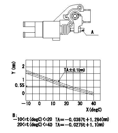
Adjustment of the W-CSD
Adjust the timer stroke using the screw so that it is as determined from the graph.
Caution: The temperature of the wax at adjustment must not exceed a.
A:Screw
B:Timer stroke graph
X:Temperature t
Y:Timer stroke TA
----------
a=30degC
----------
----------
a=30degC
----------
0000001901 DASHPOT ADJUSTMENT
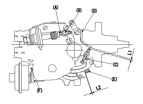
Adjustment of the dash pot
1. Insert a block gauge L1 (thickness gauge) between the idle set screw (C) and the control lever (D).
2. In the above condition, adjust the position of the dash pot so that the dash pot adjustment screw (A) contacts the push rod and then fix the screw using the nut (B).
TT
Note:
(1)Confirm that the dashpot and control lever contact faces are smooth.
(2)Confirm that the control lever returns to the idling position.
ISC actuator installation
1. Maintain the control lever in the idling position.
2. Fix actuator bracket (F) so that the gap between the control lever and the ISC lever's roller (E) is L2.
----------
T=6~7N-m(0.6~0.7kgf-m) L1=2.7+-0.05mm L2=1.0+1.0-0.5mm
----------
L1=2.7+-0.05mm L2=1.0+1.0-0.5mm
----------
T=6~7N-m(0.6~0.7kgf-m) L1=2.7+-0.05mm L2=1.0+1.0-0.5mm
----------
L1=2.7+-0.05mm L2=1.0+1.0-0.5mm
Information:
Lubrication System
OIL LUBRICATION SCHEMATICThe lubrication system is the pressure type. The oil pump draws oil from the sump through a suction pipe and strainer to the pump. The oil pump is driven by the auxiliary drive group which is driven by the timing gears.Pressure oil flows to the oil cooler. The oil cooler is cooled by water from the cooling system. Coolers on T6.3544 Engines have a bypass valve that allows the oil to go around the cooler in case of a restriction or if the oil is too cold and thick. From the cooler, oil passes through the relief valve. On T6.3544 Engines, the relief valve is two stage. At 205 to 225 kPa (30 to 37 psi), oil is fed by a pipe to the piston cooling jet gallery which is a drilled passage the length of the crankcase, above the camshaft chamber. The piston cooling jets are bolted into the gallery and point into the bottom of each cylinder. Oil is sprayed onto the underneath side of each piston which takes heat from the combustion area. The oil then drains back to sump.At 345 to 415 kPa (50 to 60 psi), oil passes through a single oil filter on 6.3544 Engines or two filters on T6.3544 Engines. Oil then flows to the main oil gallery which is a drilled passage the length of the crankcase. Oil also flows from the filters to the turbocharger bearings on T6.3544 Engines. Passages in the crankcase webs feed oil from the main oil gallery to the main bearings. Passages in the crankshaft carry oil to the big end bearings. Through passages in No. 1, 3, 5 and 7 crankcase webs, oil passes from the main bearings to lubricate the camshaft bearings.The No. 2 camshaft bearing supplies a controlled amount of oil to the rocker shaft assembly, which then flows through a small bleed hole in each rocker lever to lubricate the valves and springs.Pistons, cylinder liners, connecting rod small end bushings, cam lobes and valve lifters are splash and oil mist lubricated.Oil flows from the main oil gallery to the two idler gear hubs. The oil passes through the hubs to radial passages in the idler gears to lubricate the teeth of the timing gears.The auxiliary drive group shaft bearings are lubricated by a passage from the main oil gallery to the front auxiliary drive shaft bearing. Oil then passes around a groove in the bearing journal and through another passage along the outer side of the auxiliary drive housing to the rear auxiliary drive shaft bearing. The upper fuel pump bearing is also lubricated from this passage. Also connected to this outer housing passage is a spray tube which directs oil on to the auxiliary drive shaft (worn gear) and gear assembly (worm wheel).Air Inlet And Exhaust System
6.3544 Engines
AIR INLET AND EXHAUST SYSTEM COMPONENTS
1. Exhaust manifold. 2. Inlet manifold. 3. Engine cylinderThe air inlet and exhaust system components on naturally aspirated engines are: the air cleaner, inlet manifold,